2002 HONDA CIVIC fuses
[x] Cancel search: fusesPage 896 of 1139

IVehicle Speed Signal Circuit Troubleshooting
Special Tools Required:
Test Harness 07LAJ-PT3020A
Before testing, inspect the No. 4 (10A) and No. 10 (7.5A)
fuses in the under-dash fuse/relay box.
1. Disconnect the 3P connector from the vehicle
speed sensor (VSS) {A).
Connect the test harness only to the engine wire
harness.
Connect the RED test harness clip (B) to the positive
probe of an ohmmeter. Cover the white (C) and
green {D) test harness leads with protective tape (E).
Check for continuity between the RED test harness
clip and body ground,
ls there continuity?
YES Go to step 5.
NO Repair open in the BLK wire between the VSS
and G 101.I
3.
4.
5. Connect the WHT test harness cliD (B) to the
positive probe of a voltmeter, and connect the RED
test harness clip (C) to the negative probe.
Turn the ignition switch ON (ll).
le thara h2ltarv v^ltada?
YES-Go to step 7.
NO Repair open in the BLK,/YEL wire between the
VSS and the under-dash fuse/relay box.l
Disconnect the WHT test harness clip (B).
Connect the GRN test harness clip {D) to the
positive probe of a voltmeter.
Is there 5 V or more?
YES- Go to step 9.
NO Repair short or open in the BLUMHT or WHT/
GRN wire between the VSS and the cruise control
unit, or the ECM.I
(cont'd)
7.
8.
22-65
Page 1003 of 1139

Multiplex Control System
Troubleshooting
Mode 1 Tset
1. Remove the driver's dashboard lower cover {see
page 20-59).
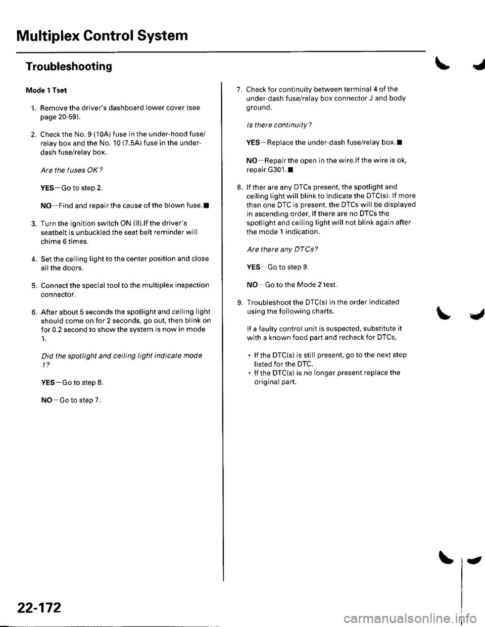
2. Check the No. 9 ( 10A) fuse in the under-hood fuse/
relay box and the No. 10 (7.5A) fuse in the under-
dash fuse/relay box.
Are the fuses OK?
YES-Go to step 2.
NO-Find and repairthe cause ofthe blown fuse.!
3. Turn the ignition switch ON (ll).lf the driver's
seatbelt is unbuckled the seat belt reminder will
chime 6 times.
4. Set the ceiling light to the center position and close
allthe doors.
5. Connect the specialtoolto the multiplex inspection
conneclor.
6. After about 5 seconds the spotlight and ceiling light
should come on for 2 seconds, go out, then blink on
for 0.2 second to show the system is now in mode
1.
Did the spotlight and ceiling light indicate mode
1?
YES-Go to step 8.
NO Go to step 7.
22-172
-
7. Check for continuity between terminal 4ofthe
under-dash fuse/relay box connector J and body
ground.
ls there continuity?
YES Replace the under-dash fuse/relay box.l
NO - Repair the open in the wire.lf the wire is ok,
repair G301.1
8. lf ther are any DTCS present, the spotlight and
ceiling light will blink to indicate the DTC(S). lf more
than one DTC is present, the DTCS will be displayed
in ascending order, lf there are no DTCS the
spotlight and ceiling light will not blink again after
the mode 1 indication.
Are there any DTCg?
YES Go to step 9.
NO Go to the Mode 2 test.
9. Troubleshoot the DTC(S) in the order indicated
using the following charts.
lf a faulty control unit is suspected, substitute it
with a known food part and recheck for DTCS,
. lf the DTC(s) isstill present. go to the next step
listed for the DTC.. lf the DTC(S) is no longer present replace the
original part.
Page 1133 of 1139

Service Manual lndex
)s
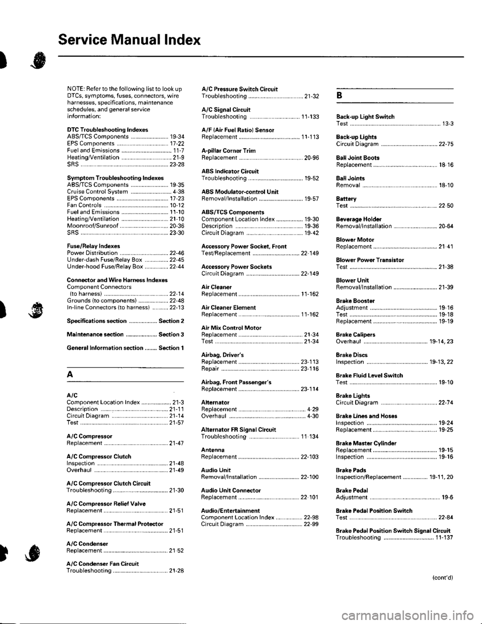
NOTE: Referto the lollowing listto look up A/C Pressure Switch CircuitDTCS, symptoms, fuses, connectors, wire Troubleshooting ......... ...-.-....-...-.-.-....-..21-32 Bharnesses, specifications, maintenanceschedules, and general serviceinlormation:
DTC Troubleshooting Indexes
A/C Signal CircuitTroubleshooting.........................-...... 11-'133 Back-up Light SwitchTest .......................................................... 13'3A/F lAir Fuel Ratiol SensorABS/TCS Components ........................ 19-34 Replacement ....................................... 1 1-113 Back-up Li9ht3EPS Components ................................. '17-22 Circuit DiagramFueland Emissions11-i A-Dillar Corner Trim
ABS Indicator Circuit
Heating/Ventilation ................................ 21-9 Replacement ...............-.....-..............-.... 20,96 Ball Joint BootssRS ........................................................ 23-28Replacement ......
... 19-52 Ball Joints
22-75
18 16
Remova1.............-.......... . ...........18-10Symptom Troubleshooting Indexes TroubleshootingABS/TCSComponents........................ 19 35Cruise Control System ..........................4 38 ABS Modulator-contml UnitEPS Components ................................. 17-23 Bemoval/lnstallation ............................ 19-57 BettervFan Controls10,12
Accessory Powor Socket Front
Blowor Pow€r Transistor
.......22 50
Blower UnitRemoval/lnstallation ............................ 21-39
Fuel and Em issions .............................. 11-10 ABS/TCS ComoonentsHeating/Ventilation..............................21 10 Component Location Index ................. 19-30 Beverage Holder
SRS ........................................................ 23'30 CircuitDiaqram.......................... 19'42Blower MotorReplacement .....21 41
21-38
Power 0istribution ...............................22-46 TesVReplacement .............................. 22'149Under-dash Fuse/Relay Box ............... 22 45Under-hood Fuse/Belay Box ...............22 44 Accessory Power Sockets
Fuse/Relay lndexes
(to harness)
Connector and Wire Harness lndexesComponent Connectors
Circuit Oiagram .................................. 22-149
Air Cleaner......2214 Rep1acemen1.....................................11-162
Air MixControl MotorMeintenence section .................... Section 3 Replacement ......................................... 21'34 Brake CelipersTest......................21-34 Overhaul19-14,23Gene.al lnlormation section........ Section 1
21.57
Airbag. Driver's
Ahernator FR Signal CircuitTroubleshooting .... .........-..........11 134
AntennaReplacement
Inspection ............................................. 19-24Rep|acement................. .................... 19-25
Bieke Meder Cylinder
Irake Discs
A
Replacement ....................................... 23 1 'l3 Inspection .................... ................... 19-13,22Repair ...........-...................................... 23 1 16Brake Fluid Level SwitchAirbag. Front Passenger's TestBeplacement....................................... 23-1 14AIC Brake LightsComponent Location fndex ...................21-3 Altemator CircuitDiagram....................................22-74Description.....................................-....21'1'l Beplacement ................ ........................... 4 29CircuitDiagram....................................21-14 Overhaul .................................................4-30 Brake Lines and Hoses
19.10
A/C CompressolReplacement .......-...-............................. 21 -41
A/C Compr€ssor ClulchRep1acement......................................... 19-15.........22-103 Inspection ............................................. 19-16Inspecton........Overhaul ..........
A/C CondenserReplacement,.,
21-442l-49 Audio Unit
Replacement
Brake PadsRemoval/lnstallation .. ........................22-100 Inspection/Rep1acement................ 19-11,20A/C Compressor Clutch CircuitTroubleshooting ................................... 21-30 Audio Unit Connector Brake Pedal22101 Adjustment..............19,6ArfC Comoressor Relief ValvcReplacement ..........-...-.......................... 21-51 Audio/Entertainment
A/C Compr$sor Thermal Protector Circuit DiagramReplacement............-............................ 21-51
Component Location In dex .................22-9A Test .......-.............. 22-84Breke Pedal Posilion Switch
Brake Pedal Position Switch Signal Clrcuit11-137
.....21 52
A/C Condenser Fan CircuitTroubleshooting ................... . . . . . .....21-28
)s
Troubleshooting
(cont'd)
Page 1135 of 1139

)
Orive BehInspecaron................ 4-26
Door PanelsRemoval/lnstallation -............................. 20-4
Door Sash TrimRep1acement......................................... 20 10
Door StrikersAdiustment ........................................... 20-13
Door Weatherst psBeplacement...........-............................. 20 1 1
EPS Conirol UnitRemoval/1nsta11ation ..................-......... 17-67
EPS Indicator CircuitTroubleshooting ................................... 17 -47
EPS MotorRemoval/lnstallation .-.......................... 17-49
EVAP CanisterRep1acement......................... ......... 11,189
EVAP Control Syst€mComponentLocation Index ..............'11-170
EVAP Two-Wey ValveTest ..........-.............-............................ 11 186
Evaporetor CoreRep1acement........................ . ... 21-42
Evaporator Tomperature SensorReplacement......................................... 21 -37Test..................................... ..........2137
EvaporrtoFHeater UnitReplacement........................................ 21 43
Exhaust ManifoldRemoval/1nsta11ation ................................ I 7
Exhaust Pipe8ep|acement............................................. 9-8
Front SpeakersRep|acement....................................... 22-102
Front SuspensionComponentLocation Index................... 18-3
Fueland EmissionsDescription ........................................... 11-12
Fuel Fill DoorAdjustment ..........-................................ 20 93
Fuel Fill Door OpenetBeplacement........................ . ............ 20.109
Fuel Fill Door Opener CableReplacement....................................... 20- lO7
Fuel FilterReplacement....................................... 1 1-152
Fuel Gauge Sending UnitTest ......................-.-..........-.................. 11'156
Fuel Injection Syslem (PGM"FIlComponent Location 1ndex................. 11-49
Fuel IniectorsRep1acemen1....................................... 1 1 1 1 l
Fuel Lines and HosesInspection .......................................... 1 1'146Removal ....................... . .. . .... 11-149Insta|1ation .......................................... 1 1 150
FuelPipe ProtectolReplacement....................................... 20-104
Fuel Pressure RegulatotReplacement....................................... 1 1-152
Fuel Pulsation DamperReplacemenl................................... 11 154
Fuel PumpReplacement,,,,,.,.,.,,,.,,,,,,,,,,,,.,.,.,,,..,.. 11-153
Fuel Pump CircuitTroubleshooting -.......-....................... 1 1-141
FuelSupply SystemComponent Location lndex .............. 11 140Adjustment................................... 11-144Test........-...-................. ... ............- 11-145
FuelTankBeplacemenl.............. . ..... .. 11 155
Fuel Tank Vapor ControlValveTest ......................-....... ... . . 11-187Replacement,,.,,...,.,,,.,.,,,,... .. .. 11 189
Fuses{See first page ofthis Index)
)
Rep|acement................. ..................... 4 26
Drive Belt Auto-tensionellnspection ............................................... 4 21Rep1acement.................................... ..4-28
Driver's PocketRemoval/lnstallation -........................... 20-60
Driver's TrayRemoval/lnstallation .........................-.- 20-65
DRL {Daytime Running LightslControl Unitlnput Test .................... ........ . . . ......22-16
DTCs(See first page olthis Index)
Dust and Pollen FillerReplacement......................................... 21-39
Dynamic Damper, DriveshaftsReplacement........................................... 16-8
ECT SensorReplacement.,.,,,.,.,,,,,,,,,,,,,,................ 1 1-1 14
El€ctrical Power Steering IEPS)Signal CircuitTroubleshooting ........ ... .. 11-135
EmblemsReplacement......................-................ 20-100
Engine AssemblyRemova1 .................................................... 5 2Installation ............._.................................. 5-9
Engine Block AssemblyComponent Location Inder ..................... 7.3
Engine Block, BareInspect|onRepair
Fan ControlsComponent Location Index................. 10'l 1Circuit Diagram .. ..... . .. . .................. 10 13
Fender Fairing, FrontReplacement...-................................... 20-103
Final Driven Gear. M/TReplacement.... . . ................................ 13-53
FrameRepair Chan............ ... ....................... 20 11 4
Frame StiffenelReplacement......-................................ 20- J'13
Front ConsoleRemoval/lnstallation ............................ 20 5lDisassembJy/Reassemb|y ................... 20 58
Front DoorsComponent Location Index................... 20-2Adiustment ........................................... 20.12
Front Driveshaft AssemblyInspeclion .................... ... ....16 3Remova1...................-...... ... .....16-3Disassembly ............................... .....165Resassemb|y ................................-......... 16-9Insta11arion ........................ ...... ............ l6 17
Front lmpact SensorsRep1acement............................ ...23 125
................7-15................1 11
)
Entry Light Control SystemComponent Location Index ...............-. 22-89Circuit Dia9ram .................................... 22 90
EPS ComponentsComponent Location 1ndex..........-...... 17-!7Description ........................ ...... ..17-24Circuit Diagram11 26(cont'd)