Page 109 of 1139
Cylinder Head
14.
Cam Chain Removal (cont'd)
Loosely install the crankshaft pulley.
Turn the crankshaft counterclockwise to compress
the auto-lensioner,
Align the holes on the lock (A) and the auto-
tensioner (B), then insen a 1.5 mm (0.06 in.)
diameter pin (C) into the holes. Turn the crankshaft
clockwise to secure the Din.
t5.
6-14
\-
(\
16. Remove the auto-tensioner.
a
17. Remove the cam chain guide B.
gffi
llll
UU
Page 110 of 1139
t
18. Remove the cam chain guide A (A) and tensioner
arm (B).
g"'-
19. Remove the cam chain.
,ot./6. | \{n$1J;
Cam Chain Installation
NOTE: Keep the cam chain away from magnetic fields.
1. Set the crankshaft to top dead center (TDC). Align
the TDC mark {A) on the crankshaft sprocket with
the pointer (B) on the cylinder block.
Setthe camshafts to TDC. The punch mark (A) on
the variable valve timing control {VTC) actuator and
the punch mark (B) on the exhaust camshaft
sprocket should be at the top. Align the TDC marks
(C) on the VTC actuator and exhaust camshaft
sprocKet.
(cont'd )
6-15
Page 111 of 1139
Gylinder Head
Cam Chain Installation (cont'dl
3. Installthe cam chain on the crankshaft sprocket
with the colored piece (A) aligned with the punch
mark (B) on the crankshaft sprocket.
Installthe cam chain on the VTC actuator and
exhaust camshaft sprocket with the punch marks(A) aligned with the two colored pieces (B).
B
6-16
{\
5. Installthe cam chain guide A (A) and tensioner arm(B).
6x1.0mm12 N.m{1,2 kgf.m,8.7 tbf.ftt
I'6
8 x 1.25 mm22 N.m12.2kgt.m,16 tbf.ft)
6. Install the auto-tensi
6x1,0mm12Nm(1.2 kgt.m, 8.7 lbf ti)
a
a
Page 114 of 1139
19.
20.
lnstall the variable valve timing control (VTC) oil
control solenoid valve (see step 1 on page 11'127).
Connect the crankshaft position (CKP) sensor
connector {A) and VTC oil control solenoid valve
connector (B).
21. Install the crankshaft pulley (see page 6-12).
22. Installthe cylinder head cover (see page 6-41).
23. Installthe drive belt.
24. Installthe splash shield.
€D@
Auto-Tensioner RemovaU
lnstallation
Removal:
1. Remove the chain case cover.
Turn the crankshaft counterclockwise to compress
the auto-tensroner.
{cont'd)
6-19
Page 115 of 1139
Gylinder Head
Auto-Tensioner Removal/l nstallation
3. Align the holes on the lock (A) and the auto-
tensioner (B), then insert a 1.5 mm (0.06 in.)
diameter pin (C) into the holes. Turn the crankshaft
clockwise to secure the oin.
4. Remove the auto-tensioner.
6-20
\-
(cont'dl
Installation:
1. Install the auto-tensioner.
\
6x1.0mm12 N.m {1.2 kgt.m, 8.7 lbt.tt)
Remove the pin from the auto-tensioner.
a\
Page 134 of 1139
Cylinder Head Installation
Install the cylinder head in the reverse order of
removat:
1. Clean the cylinder head and block surface.
2. Install the new cylinder head gasket (A) anddowel
pins (B) on the cylinder block. Always use a new
cylinder head gasket.
Set the crankshaft to top dead center {TDC). Align
the TDC mark (A) on the crankshaft sprocket with
the pointer (B) on the cylinder block.
4. Install the cylinder head on the block.
5. Measure the diameter of each cylinder head bolt at
ooint A and Doint B.
a 50 mm (2.0 in.l
f.f )>-
A '15 mm {'1.8 in.)"<>.
lf either diameter is less than 10.6 mm {0.42 in.),
replace the cvlinder head bolt.
(cont d)
6-39
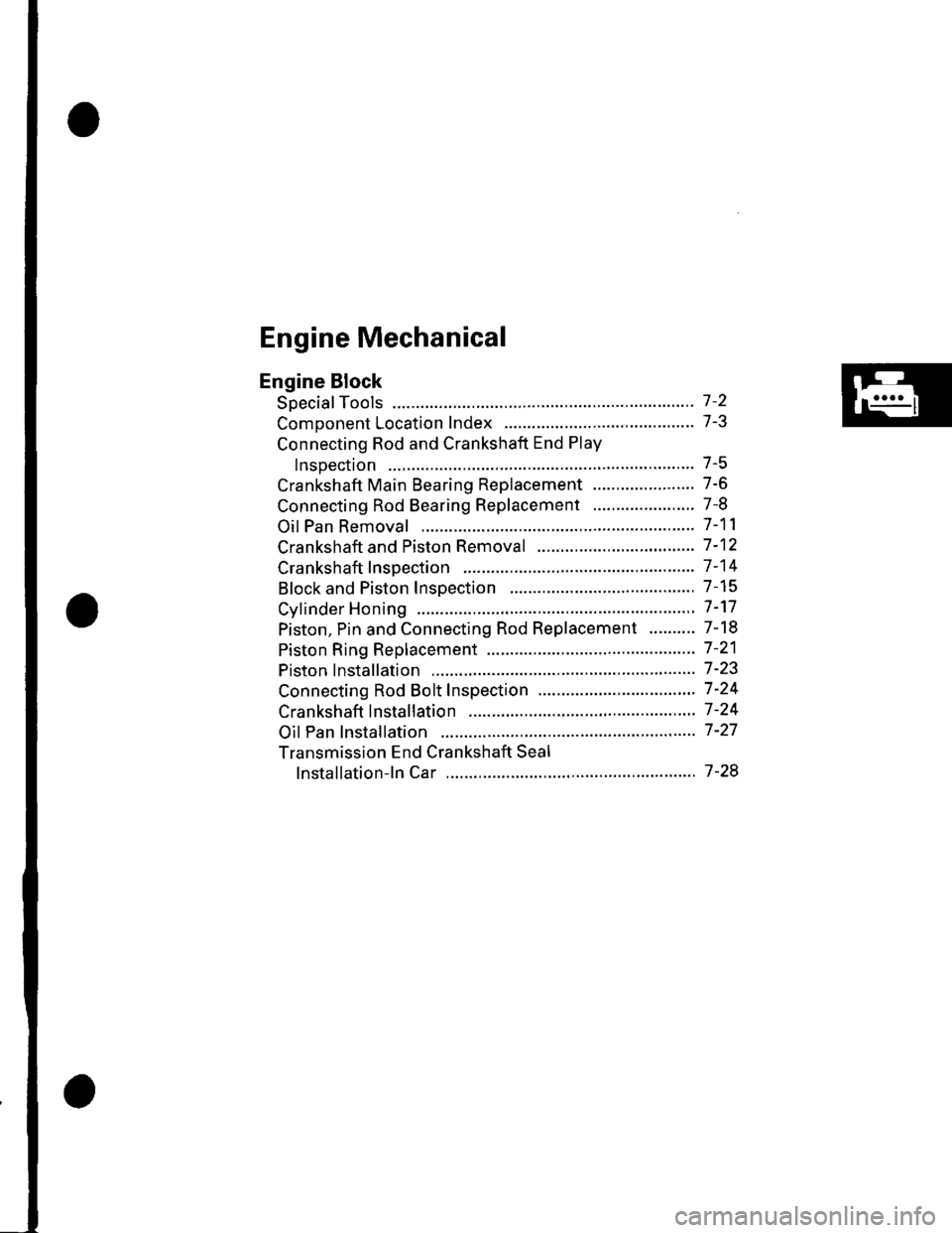
Page 139 of 1139

Engine Mechanical
Engine Block
Soecial Tools ............. 7 -2
Comoonent Location Index ......................................... 7-3
Connecting Rod and Crankshaft End Play
InsDection .............. 7-5
Crankshaft Main Bearing Replacement ...................... 7-6
Connecting Rod Bearing Replacement ...................... 7-8
Oil Pan Removal ....................... .......... 7-11
Crankshaft and Piston Removal ........ 7-12
Crankshaft Inspection ........................ 7-14
Block and Piston Insoection ........................................ 7-15
Cyfinder Honing ............ .".................... 7 -'17
Piston, Pin and Connecting Rod Replacement .......... 7-18
Piston Ring Replacement ................... 7 -21
Piston lnstallation .................... ........... 7-23
Connecting Rod Bolt Inspection .......' 7 -24
Crankshaft lnstallation .....................'. 7-24
Oil Pan lnstallation .................. ........... 7 -27
Transmission End Crankshaft Seal
lnstallation-ln Car ................... ........' 7 -28
Page 141 of 1139
Component Location Index
MAIN BEARINGSOilclearance, page 7-6Selection, page 7-6
CRANKSHAFTEnd play, page 7-5Runout, page 7-14Out-of-Round, page 7-14Removal, page 7-12lnstallation, page 7-24
fifr"8
-4
E
I
BAFFLE PLATE
LOWER BLOCK
FLYWHEEL
CRANKSHAFT OIL SEAL.TRANSMISSION ENDInstallation, step 21 on page 7-26
THRUST WASHERS
(cont'd)
7-3