Page 152 of 1139

Engine Block
Crankshaft lnspection
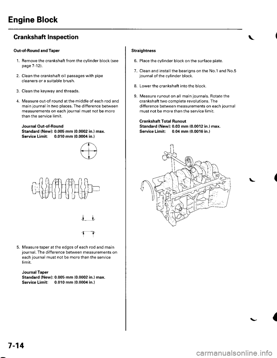
Out-ol-Round and Taper
1. Remove the crankshaft from the cylinder block (see
page 7-121.
2. Clean the crankshaft oil passages with pipe
cleaners or a suitable brush.
3. Clean the keyway and threads.
4. Measure out-of round at the middle of each rod and
main journal in two places. The difference between
measurements on each journal must not be more
than the service Iimit.
Journal Out-ot-Round
Standard (New): 0.005 mm (0.0002 in.) max.
Service Limit; 0.010 mm (0.0004 in.)
5. Measure taper at the edges of each rod and mainjournal. The difference between measurements on
each journal must not be more than the service
limit.
JournalTaper
Standard lNewl: 0.005 mm (0.0002 in.) max.
Service Limit: 0.010 mm {0.0004 in.)
I_JJ
fl
7-14
\
Straightness
6. Place the cylinder block on the surface plate.
7. Clean and installthe bearigns on the No.1 and No.5journal of the cylinder block.
8. Lower the crankshaft into the block.
9. Measure runout on all main journals. Rotate the
crankshaft two complete revolutlons. The
difference between measurements on each journal
must not be more than the service limit.
Crankshaft Total Runout
Standard (New): 0.03 mm 10.0012 in.l max.
Service Limit: 0.04 mm (0.0016 in.l
(L
{
Page 153 of 1139

1.
Block and Piston Inspection
Remove the crankshaft and pistons (se e pageT -121.
Check the piston for distortion or cracks,
Measure the piston diameter at a point I1 mm {0.4in.) from the bottom of the skirt. There are two
standard-size pistons (No Letter or A, and B). The
letter is stamped on the top of the piston. Letters
are also stamped on the block as cylinder bore
stzes.
Piston Diameter:
Standard (Newl:
No Letter {or A): 85.980 85.990 mm(3.3850 3.3854 in.)
B: 85.970-85.980 mm(3.3846-3.3850 in.)
Service Limit:
No Lefter lor A): 85.930 mm (3.3831 in.)
B: 85.920 mm 13.3827 in.)
Oversize Piston Diameter:
0.25: 86.230-85.240 mm (3.3949 -3.3953 in.l
4. Measure wear and taper in direction X and Y at
three levels in each cylinder as shown. lf
measurements in any cylinder are beyond the
oversize bore service limit. replace the block. lf the
block is to be rebored, refer to step 7 after reboring.
Cylinder Bore Size
Standard (New):
A or l: 86.010 86.020 mm
13.3862 3.3866 in.)
B or ll: 86.000 86.010 mm(3.3858 3.3862 in.)
Service Limit: 86.070 mm (3.3886 in.)
Oversize:
O.25t 96.250 86.260 mm (3.3957 3.3961 in.)
Reboring limit: 0.25 mm (0.01 in.l max.
Bore Taper:
Limit: (Difference between first and third
measurement) 0.05 mm (0.002 in.)
FirstMeasurement
SecondMeasutement
ThirdMeasurement
(cont'd)
7-15
6 mm {0.2 in.}
6 mm {0.2 in.}
Page 161 of 1139

Piston Installation
lf the crankshaft is already installed
1. Setthe crankshaftto bottom dead center (BDC) for
each cylinder.
2. Remove the connecting rod caps, then install the
ring compressor, and check that the bearing is
securely in place,
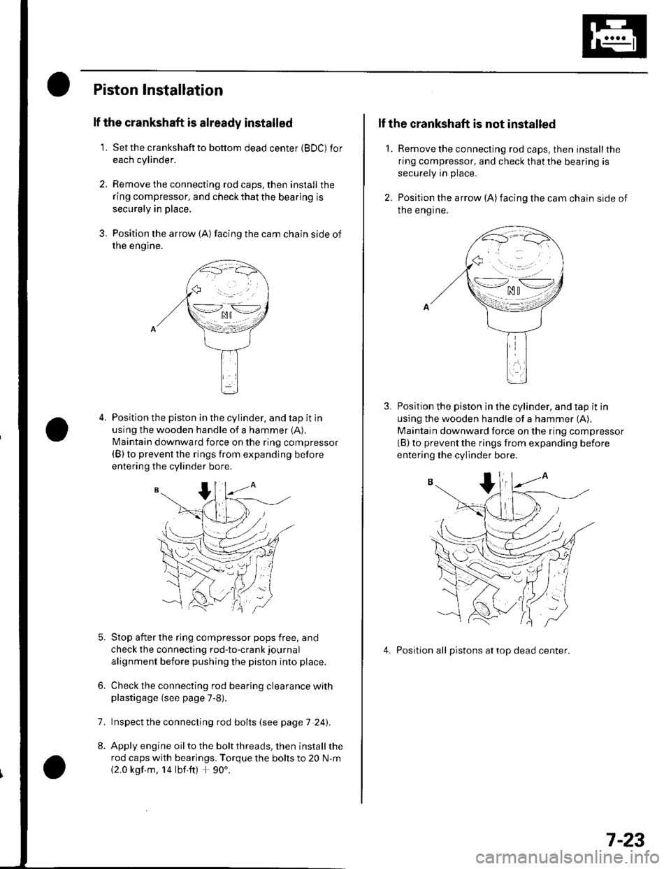
3. Position the arrow {A) facing the cam chain side of
rne engtne.
Position the piston in the cylinder, and tap it in
using the wooden handle of a hammer (A).
N4aintain downward force on the ring compressor(B) to prevent the rings from expanding before
entering the cylinder bore.
Stop after the ring compressor pops free, and
check the connecting rod-to-crank journal
alignment before pushing the piston into place.
Check the connecting rod bearing clearance withplastigage (see page 7-8).
lnspect the connecting rod bolts (see page 7 241.
Apply engine oil to the bolt threads, then install the
rod caps with bearings. Torque the bolts to 20 N.m
{2.0 kgf m, 14 lbf ft) + 90'.
6.
7.
2.
1.
lf the crankshaft is not installed
Remove the connecting rod caps. then install the
ring compressor, and check that the bearing is
securely in place.
Position the arrow (A)facing the cam chain side of
Ine engrne.
Position the piston in the cylinder, and tap it in
using the wooden handle of a hammer (A),
Maintain downward force on the ring compressor(B) to prevent the rings from expanding before
entering the cylinder bore.
4. Position all pistons attop dead center.
\--lno n\-.--l. ^u t
>-*/zi
.,.'_\pf{
wr
(( 'V,/ :
7-23
Page 162 of 1139
Engine Block
Connecting Rod Bolt Inspection
Measure the diameter of each connectinq rod bolt
at Doint A and ooint B.
35 mm
Calculate the difference in diameter between point
A and point B.
Point A-Point B = Difference in Diameter
Diflerence in Diameter:
Specification: 0 0.1 mm (0 0.004 in.)
lf the difference in diameter is out of tolerance,
replace the connecting rod bolt.
1.
3,
mm
7-24
\-
Crankshaft Installation
Special Tools Bequired. Driver 07749-0010000. Attachment, 24 x 26 mm 07746-0010700. Oil seal driver attachment 96 o7ZAD-PNAAl00
1. Install the crankshaft end bushing with the special
tools when replacing the crankshaft. Drive in the
crankshaft end bushing until the special tools
bottom aqainst the crankshaft.
07749-0010000
07746-00'l
Check the connecting rod bearing clearance with
plastigage {see page 7-8).
Check the main bearing clearance with plastigage
(see page 7-6).
lnspectthe connecting rod bolts (see pageT-241.
(
I\-(
4.
a
Page 163 of 1139

5. Installthe bearing halves in the cylinder block and
conneclrng rods.
6. Apply a coat of engine oilto the main bearings and
rod bearings.
7. Hold the crankshaft so rod journal No.2and rodjournal No. 3 are straight up, and lower the
crankshaft into the block.
8. lnstallthe thrust washers (A) in the No. 4 journal of
the cylinder block.
Apply engine oil to the threads ot the connecting
rod bolts,
Seat the rod journals into connecting rod No. 1 and
connecting rod No. 4. Line up the mark (B) on the
connecting rod and cap, then installthe caps and
bolts finger-tight.
Rotate the crankshaft clockwise, and seat thejournals into connecting rod No.2 and connecting
rod No. 3. Line up the mark on the connecting rod
and cap, then install the caps and bolts finger-tight.
9.
10.
'11 .
\-1
12. Tighten the connecting rod bolts to 20 N.m(2.0 kgf.m, 14 lbf.ft).
13. Tighten the connecting rod bolts an additional 90".
14. Remove old liquid gasket from the lower block
mating surfaces, bolts and bolt holes.
15. Clean and dry the lower block mating surfaces.
16. Apply liquid gasket, P/N 08718-0009, evenly to the
cylinder block mating surface of the lower block
and to the innerthreads ofthe bolt holes.
NOTE: Do not install the parts if 5 minutes or more
have elapsed since applying liquid gasket. Instead,
reapply liquid gasket after removing old residue.
(cont'd)
.\
,i,
Apply liquid gasketalong the broken line.
7-25
Page 164 of 1139
Engine Block
Crankshaft Installation (cont'd)
Put the lower block on lhe cylinder block.
Tighten the bearing cap bolts in sequence to
29 N.m (3.0 kgf m, 22 lbf.ft).
Tighten the bearing cap bolts an additional 56".
Tighten the I mm bolts in sequence to 22 N.m 12.2kgf m, 16 lbf.ft).
'17 .
18.
19.
20.
7-26
{
2'1. Use the specialtools to drive a new oil seal
squarely into the block to the specified installed
height.
07749-0010000
Measure the distance between the crankshaft (A)
and oil seal (B).
Oil Seal Insialled Height: 5.5 6.5 mm
|10.22 0.26 in.l
5.5-6.5 mm{0.22 0.26 in.l
{\
07zAo-PNAA100
Page 166 of 1139

Engine Block
Oil Pan Installation (cont'dl
6. lf the engine is still in the vehicle, install the
subframe,
-1 Installthe subframe. Align the reference lines
on the subframe with the bolt head center, then
tighten the bolts (see step 5 on page 5-10).-2 Tighten the front mounting bolt (see step 6 onpage 5-10).-3 Tighten the rear mount mounting bolts (see
step 7 on page 5-11).-4 Connect the suspension lower arm ball joints
(see step 6 on page 18-19).
7. After assembly, wait at least 30 minutes before
filling the engine with oil.
7-28
v
Transmission End Grankshaft Seal
Installation - In Car
Special Tools Required. Driver 07749-0010000. Oil seal driver attach ment 96 07ZAD-PNAA100
'1. Dry the crankshaft oil seal housing.
2. Use the special tools to drive a new oil seal
squarely into the block to the specified installed
height.
07749-0010000
and oil seal (B).
Oil Seal Installed Height:
5.5 6.5 mm 10.22-0.26 in.l
5.5 6.5 mml0.22- O.26 in .l
I
/$rRfr4T
tr*W(r
-]t
fl\OTZAD.PNAAlOO
Measure the distance between the crankshaft (A)
a
Page 170 of 1139

Engine Lubrication
Oil Pressure Switch Test
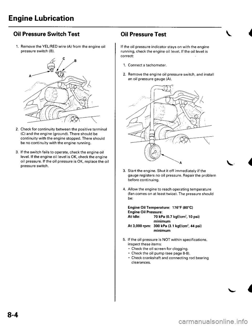
1. Remove the YEURED wire (A)from the engine oilpressure switch (B).
Check for continuity between the positive terminal(C) and the engine (ground). There should be
continuity with the engine stopped. There should
be no continuity with the engine running.
lf the switch fails to operate, check the engine oil
level. lf the engine oil level is OK. check the engine
oil pressure. lf the oil pressure is OK, replace lhe oil
Dressure switch.
2.
8-4
Oil Pressure Test
lf the oil pressure indicator stays on with the engine
running. check the engine oil level. lf the oil level is
correct:
Connect a tachometer.
Remove the engine oil pressure switch, and install
an oil pressure gauge {A).
{
'1.
\.(
4.
Sta rt the engine. Shut it off immediately if thegauge registers no oil pressure. Repair lhe problem
before continuing.
Allow the engine to reach operating temperature(fan comes on at least twice), The pressure should
be:
Engine Oil Temperature: 176'F (80'Cl
Engine Oil Pressure:
At ldle:70 kPa (0.7 kgf/cm', 10 psi)
mtntmum
At 3,000 rpm: 300 kPa (3.1 kgf/cm',44 psi)
minimum
lf the oil pressure is NOT within specifications,
inspect these items:. Check the oil screenforclogging.. Check the oil pump (see page 8-8).. Check crankshaft and connecting rod bearing
clearances.
I