2002 HONDA CIVIC Temperature Sensor
[x] Cancel search: Temperature SensorPage 232 of 1139

Vacuum Hose Routing
I
O AIR FUEL RATIO IA/F) SENSOR {SENSOR 1}O SECONDARY HEATED OXYGEN SENSORISECONDARY HO2S} {SENSOR 2}
O MANIFOLD ABSOLUTE PRESSURE (MAPI SENSORO ENGINE COOLANT TEMPERATURE {ECT) SENSORO INTAKE AIR TEMPERATURE (IAT) SENSORO CRANKSHAFT POSITION (CKP) SENSORO KNOCK SENSORO CAMSHAFT POSITION (CMPI SENSOR BITOP DEAD CENTER ITDC) SENSOR)
O CAMSHAFT POSITION ICMPI SENSOR A@ IDLE AIR CONTROL (IACI VALVEO THRONLE BODY.O INJECTOR@ FUEL PULSATION OAMPER[I FUEL FILTER@ FUEL PRESSURE REGULATOR@ FUEL PUMP@ FUEL TANK
@ RESONATOR(9 AIR CLEANER@ POSITIVE CRANKCASE VENTILATION {PCVI VALVE@ THREE WAY CATALYTIC CONVERTER@ EVAPORATIVE EMISSION {EVAPI CANISTER@ EVAPORATIVE EMISSION {EVAP) CANISTERPURGE VALVE{} EVAPORATIVE EMISSION (EVAPI CANISTERVENT SHUT VALVE{' EVAPORATIVE EMISSION {EVAP) TWO WAY VALVE@ EVAPORATIVE EMISSION IEVAPI BYPASSSOLENOID VALVE@ FUEL TANK PRESSURE (FTP) SENSOR@ EVAPORATIVE EMISSION IEVAP} VALVE@ FUEL TANK VAPOR CONTROL VALVE60) FUEL TANK VAPOR RECIRCULATION VALVEO INTAKE AIR BYPASS CONTROL THERMAL VALVE
(cont'd)
11-25
Page 233 of 1139
Fuel and Emissions Systems
System Descriptions (cont'd)
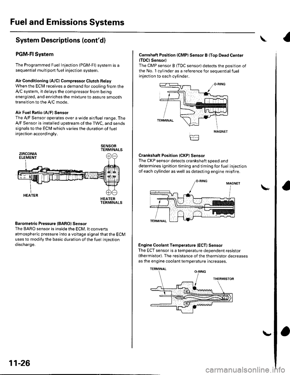
PGM-FI System
The Programmed Fuel Injection (PGM-Fl) system is a
sequential multiport fuel injection system.
Air Conditioning {A/C) Compressor Glutch Relay
When the ECfM receives a demand for cooling from the
Ay'C system, it delays the compressor from being
energized, and enriches the mixture to assure smooth
transition to the AVC mode.
Air Fuel Ratio lA/Fl Sensor
The Ay'F Sensor operates over a wide airlfuel range. The
Ay'F Sensor is installed upstream of the TWC, and sends
signals to the ECM which varies the duration of fuel
injection accordingly.
SENSORTERMINALS
HEATERTERMINALS
Barometric Pressure {BAROI Sensor
The BARO sensor is inside the ECM. lt convens
atmospheric pressure into a voltage signal that the ECM
uses to modify the basic duration of the fuel injection
discharge.
ztRcoNtaELEMENT
HEATER
11-26
\,
Camshaft Position (CMPI Sensor B (Top Dead Center(TDCI Sensor)
The CMP sensor B (TDC sensor) detects the position of
the No. 1 cylinder as a reference for sequential fuel
injection to each cylinder.
Crankshaft Position (CKPI Sensor
The CKP sensor detects crankshaft soeed and
determines ignition timing and timing for fuel injection
of each cylinder as well as detecting engine misfire.
Engine Coolant Temperature (ECT) Sensor
The ECT sensor is a temperature dependent resistor(thermistor). The resistance of the thermistor decreases
as the engine coolant temperature increases.
MAGNET
TERMINAL
Page 234 of 1139

lgnition Timing Control
The ECM contains the memory for basic ignition timing
at various engine speeds and manifold absolute
pressure. lt also adjusts the timing according to engine
coolant temperature.
Iniector Timing and Duration
The ECM contains the memory for basic discharge
duration at various engine speeds and manifold
pressures. The basic discharge duration, after being
read out from the memory, is further modified by
signals sent from various sensors to obtain the final
discharge duration.
By monitoring long term fuel trim, the ECM detects long
term malfunctions in the fuel system and sets a
Diagnostic Trouble Code {DTC).
Intake Air Temperature (lAT) Sensor
The IAT sensor is a temperature dependent resistor
{thermistor). The resistance of the thermistor decreases
as the intake air temDerature increases.
Knock Sensor
The knock control system adjusts the ignition timing to
minimize knock.
PIEZOCERAMIC
Malfunction Indicator Lamp lMlLl Indication {ln relation
to Readiness Codes)
The vehicle has certain "readiness codes" that are part
of the on-board diagnostics for the emissions systems.
lf the vehicle's baftery has been disconnected or gone
dead. if the DTCS have been cleared, or if the ECM has
been reset. these codes are set to incomplete. In some
states, part of the emissions testing is to make sure
these codes are set to comDlete. lf all of them are not
set to complete, the vehicle may fail the test and the
test cannot be finished.
To check if the readiness codes are set to complete,
turn the ignition switch ON (ll). but do not start the
engine.TheMILwill comeonforlS 20seconds. lf it
then goes off, the readiness codes are set to complete,
lf it blinks severaltimes, one or more readiness codes
are not set to comolete. To set each code, drive the
vehicle or run the engine as described in the
procedures to set them in this section (see page 1 1-46).
Manifold Absolute Pressure {MAP) Senso]
The MAP sensor converts manifold absolute pressure
into electrical signals to the ECM.
SENSOR UNIT
(cont'd)
11-27
Page 243 of 1139

Fuel and Emissions Systems
System Descriptions (cont'dl
ldle Control System Diagram
The idle speed of the engine is controlled by the ldle Air Control (lAC) varve:
'Aftertheenginestarts,theIACvalveopensforacertainamountoftime.Theamountofairisincreasedtoraisethe
idle sDeed.. When the engine coolant temperature is low, the IAC valve is opened to obtain the proper fast idle speed. Theamount of bypassed air is controlled in relation to engine coolant temperature.
INTAKE MANIFOLDIAC VALVEAKE AIR DUCT
CLEANER
\
BLK/REO
YEL/BLK ---< FromPGM.FIMAINRELAY
THROTTLE AODY
Intake Air System Diagram
This system supplies air for engine needs. A resonator in the intake air
drawn into the svstem.
VARIOUSSENSOnS
pipe provides additional silencing as air is
THROTTLE AODYVARIOUSSENSORS
BLK
BLK
I
11-36
{
Page 253 of 1139

Fuel and Emissions Systems
How to Set Readiness Codes
Malfunction lndicator Lamp (MlL) Indication
(ln relation to Readiness Codesl
The vehicle has certain "readiness codes" that are part
of the on-board diagnostics for the emissions systems.
lf the vehicle's battery has been disconnected or gone
dead, if the DTCS have been cleared, or if the ECM has
been reset, these codes are set to incomplete. In some
states, part of the emission testing is to make su re these
codes are set to complete. lf all of them are not set to
complete, the vehicle may fail the emission test, or the
test cannot be finished.
To check ifthe readiness codes are complete, turn the
ignition switch ON (ll), but do not start the engine. The
MIL will come on for 15 20 seconds. lf it then goes off,
the readiness codes are complete. lf it blinks several
times, one or more readiness codes are not complete.
To set readlness codes from incomplete to complete.
do the procedure for the appropriate code.
11-46
L
Catalytic Converter Monitor and Readiness
Code
NOTE:. Do not turn the ignition switch off during the
procedure.
. All readiness codes are cleared when the battery is
disconnected or when the ECM is cleared with the
OBD ll scan tool or Honda PG lvl Tester.. Low ambient temperatures or excessive slop-and-go
traffic may increase the drive time needed to switch
the readiness code from incomplete to complete.' The readiness code will not switch to com Dlete until
all the enable criteria are met.. lf a fault in the secondary HO2S system caused the
MIL to come on. the readiness code cannot be set to
comDlete until vou correct the fault.
Enable Criteria. ECT at 158"F (70'C) or higher.. Intake air temperature (lAT) at 20"F (-7'C) or higher.. Vehicle speed is steady, and vehicle speed sensor
(VSS) reads more then 25 mph (13km/h).
Procedure
1. Connect the scan tool to the vehicle's data link \
connector (DLCi, and bring up the tool's generic \"
OBD ll mode.
Start the engine.
Test-drive the vehicle under stop-and-go conditions
with short periods of steady cruise. After about
5 miles (3 km), the readiness code should switch
from incomplete to complete.
lf the readiness code is still set to incomplete, check
for a temporary DTC. lf there is no DTC, one or
more of the enable crlteria were probably not met;
2.
3.
Page 254 of 1139

Evaporative Emissions (EVAP) Control
System Monitor and Readiness code
NOTE:
All readiness code are cleared when the batterV is
disconnected or when the ECM is cleared with the
OBD ll scan tool or Honda PGM Tester.
The enable criteria must be repeated if the intake air
temperature (lAT) drops lower than 36'F (20"C) from
its value at engine $an up.
Enable Criteria
At engine start up, ECT and IAT are higher than 32'F(0"C) , but lower than 95'F (35"C).
At engine start up, the ECT and IAT are within 12'F(7'C) of each other.
Procedure
1. Connect the scan tool to the vehicle's data link
connector (DLC), and bring up the tool's generic
OBD ll mode.
2. Start the engine.
3. Test-drive the vehicle under stop-and-go conditions
with short periods of steady cruise. After about
2.5 miles (1.6 km), the readiness code should
switch f rom incomplete to complete.
4. lf the readinesscode isstill setto incomplete, check
for a temporary DTC. lf there is no DTC, one or
more of the enable criteria were probably not met;
repeat the procedure.
Air Fuel Ratio (A/Fl Sensor Monitor and
Readiness Code
NOTE:. Do not turn the ignition switch off during the
orocedure.. All readiness codes are cleared when the baftery is
disconnected or when the ECM is cleared with the
OBD ll scan tool or Honda PGM Tester.
Enable Criteria
ECT at 140'F (60"C) or higher.
Procedure
1. Connect the scan toolto the vehicle's data link
connector (DLC), and bring up the tool's generic
OBD ll mode.
2. Start the engine.
3. Test-drive the vehicle under stop-and-go conditions
with short periods of steady cruise. During the
drive, decelerate (wirh the throttle fully closed) for
5 seconds. After about 3.5 miles (2.2 km). the
readiness code should switch from incomDlete to
complete.
4. lfthereadinesscodeisstill set to incomplete, check
for a temporary DTC. lfthere is no DTC, the enable
criteria was probably not meU repeat the procedure.
Air/Fuel Ratio (A/Fl Sensor Heater Monitor
Readiness Code
NOTE; All readiness codes are cleared when the battery
is disconnected or when the ECM is cleared with the
OBD ll scan tool or Honda PGM Tester,
Procedure'1. Connect the scan tool to the vehicle's data link
connector {DLC), and bring up the tool's generic
OBD ll mode.
2. Start the engine, and let it idle for 1 minute. The
readiness code should switch from incomplete to
comDlete.
3. lf the readiness code is still set to incomplete, check
for a temporary DTC. lf there is no DTC, repeat theproceoure.
(cont'd)
11-47
Page 256 of 1139
![HONDA CIVIC 2002 7.G Workshop Manual PGM-FI System
Component Location Index
CAMSHAFT POS]TION {CMP) SENSOR B(TOP DEAD CENTER (TDC}SENSORITroubleshootina. oaoe 1 1-95Replacement, p;ge 1-1.1 14
ELECTRICAL LOADDETECTOR {ELDITroubleshooting,](/manual-img/13/5744/w960_5744-255.png "HONDA CIVIC 2002 7.G Workshop Manual PGM-FI System
Component Location Index
CAMSHAFT POS]TION {CMP) SENSOR B(TOP DEAD CENTER (TDC}SENSORITroubleshootina. oaoe 1 1-95Replacement, p;ge 1-1.1 14
ELECTRICAL LOADDETECTOR {ELDITroubleshooting,")
PGM-FI System
Component Location Index
CAMSHAFT POS]TION {CMP) SENSOR B(TOP DEAD CENTER (TDC}SENSORITroubleshootina. oaoe 1 1-95Replacement, p;ge 1-1.1 14
ELECTRICAL LOADDETECTOR {ELDITroubleshooting,page 1'l -92
INTAKE AIR TEMPERATURE{IATI SENSORTroubleshooting,page 'l'l-55
Replacement, page 11-'l 15
f- \
rl
KNOCK SENSORTroubleshooting, page 1 1-77Beplacement, page 11 115
ENGINE COOLANT TEMPERATURE(ECTI SENSORTroubleshooting, page 1 1-57Replacement, page 11 114
MANIFOLD ABSOLUTE PRESSURE(MAP) SENSORTroubleshooting, page 1 1-52
THROTTLE POSITIONITP} SENSORTroubleshooting, page 11-60CRANKSHAFT POSITIONICKPISENSORTroubleshooting, page'l 1-78Beplacement, page 1 1-'l 16
AIR FUEL RATIO {A/F)SENSOR ISENSOR 1}Trorrbleshooting, page 1 1-84Replacement, page 11- 1 13
{cont'd)
ii'- r'1
.I11 ---:,I''.!,i(..,.?:fir-J-
.....,..:--.
11-49
Page 262 of 1139

4.
DTC P0112: IAT Sensor Circuit Low Voltage
1. Turn the ignition switch ON (ll).
2. Check the IAT with the scan tool.
ls 302'F (150'C) or highet (or H-Limit in Honda
node of PGM Tester), ot 0 V indicated?
VES-Go to step 3.
NO Go to step 8.
Disconnect the IAT sensor 2P connector.
Check the IAT with the scan tool.
ls 302'F(150'C)or higher (or H-Limit in Honda
mode of PGM Testet), ot 0 V indicated?
YES-Go to step 5.
NO- Replace the IAT sensor.I
Turn the ignition switch OFF.
Disconnect ECM connector B (24P).
Check for continuity between IAT sensor 2P
connector terminal No. 2 and body ground,
IAT SENSOR2P CONNECTOR
,^ ,lr 2lt-l-----Tr---IAT_t{RED/YELI
II
Wire side of female terminais
ls there continuity?
YES Repair shon in the wire between the ECM
(B'17) and the IAT sensor.l
NO Update the ECM if it does not have the latest
software, or substitute a known-good ECM, then
recheck (see page 11-6). lf the symptom/indication
goes away with a known-good ECM, replace the
original ECM.I
5.
6.
7.
8. Check the temperature reading on the scan tool.
Be aware that if the engine is warm, the reading
will be higher than ambient temperature. lI the
engine is cold, the IAT and ECT will have the same
va lue.
ls the correct ambient temperature indicated?
YES lntermittent failure, system is OK at this time
Check for poor connections or loose terminals at
the IAT sensor and at the ECM.I
NO Replace the IAT sensor.l
11-55