2002 HONDA CIVIC Temperature Sensor
[x] Cancel search: Temperature SensorPage 801 of 1139

Heating and Air Conditioning
Radiator and Condenser Fans
Common
(cont'dl
Circuit Troubleshooting
9. Using a Backprobe Set, measure the voltage
between the No. 6 terminal of ECN4 connector B
{24P) and body ground with the ECM connectors
connecteo.
ECM CONNECTOR B {24P}
ls there battery voltage?
YES UDdate the ECM if it does not have the latest
so{tware, or substitute a known-good ECM, then
recheck (see page 11-6). lf the symptom/indication
goes away with a known-good ECM, replace the
original ECM.I
NO Repair open in the wire between the radiator
fan relay, the condenser fan relay and the ECM. t
Wire side of female terminals
21-30
Compressor Clutch Circuit
Troubleshooting
1. Check the No. 1 (20A) fuse in the under-hood
fuse/relay box, and the No. 14 {10A)fuse in the
under-dash fuse/relay box.
Are the tuses OK?
YES Go to step 2.
NO Replace the fuse(s), and recheck.I
2. Check the engine coolant temperature, the throttleposition sensor, and the idle speed (use the Honda
PGM Tester PGM-Fl data list if possible).
ls the coolant temperaturc above nomal, the
throttle position sensor rcading too high, or the
idle speed too low?
YES Troubleshoot and repair the cause of the
high engine coolant temperature, high throttle
position sensor reading, or low idle speed.l
NO-Go to step 3.
3. Remove the compressor clutch relay from the
under-hood fuse/relay box, and test it (see page 22-
51 ).
ls the relay OK?
YES Go to step 4.
NO Replace the compressor clutch relay.I
4. Measure the voltage between the No. 2 terminal of
the compressor clutch relay 4P socket and body
ground.
\
COMPfiESSON CLUTCH BELAY 'P SOCKET
ls there battery voltage?
YES Go to step 5.
NO Replace the under-hood fuse/relay box.I
Page 808 of 1139

Evaporator Temperature Sensor
Replacement
1.Remove the driver's dashboard lower cover (see
page 20-59) and the under cover (see page 20-60).
Remove the under-dash fuse/relay box (see page
22-491.
Disconnect the 2P connector (A) from the
evaporator temperature sensor (B), then remove
the connector clip (C). Remove the self-tapping
screw, and carefully pull out the evaporator
temperature.
4. Install the sensor in the reverse order of removal,
Evaporator Temperature Sensor
Test
l. Dip the sensor in ice water, and measure the
resistance between its terminals
EVAPORATOR TEMPERATURE SENSOR
2.
3.
Terminal side ol male terminals
Then pour hot water on the sensor, and check {or a
change in resistance.
Compare the resistance readings with the
specifications shown in the graph; the resistance
should be within the specifications
RESISTANCEk9
t0
32050 68 86 'F
10 20 30'c
TEMPERATURE
21-37
Page 815 of 1139

Heating and Air Conditioning
Heater Unit/Core Replacement (cont'd)
8. Remove the dashboard {see page 20-66).
9. Disconnectthe connectors (A) from the blower
motor, the recirculation control motor, the mode
control motor, and the power transistor, then
remove the wire harness clips (B) and the
connector (C). Remove the self-tapping screws and
the bracket (D).
Disconnect the connectors (A) from the evaporator
temperature sensor and the air mix control motor,
then remove the wire harness clips (B) and the
connector (C). Remove the self-tapping screw and
the cover (D). Disconnect the heater valve cable (E).
10,
7t,
21-44
11. Remove the mounting bolts, the mounting nuts,
and the heater unit.
Remove the self-tapping screws and the expansion
valve cover (A). Carefully pull out the evaporator
core (B) so you don't bend the inlet and outlet pipes.
Remove the grommet (C), then remove the self-
tapping screws and the flange cover (D). Bemove
the self-tapping screws and the pipe cover (E), then
carefully pull out the heater core (F) so you don't
bend the inlet and outlet oioes.
@
5x 1.0 mm9.8 N.m11.0 kgl m,7.2 tbf.ftl
12.
Page 828 of 1139
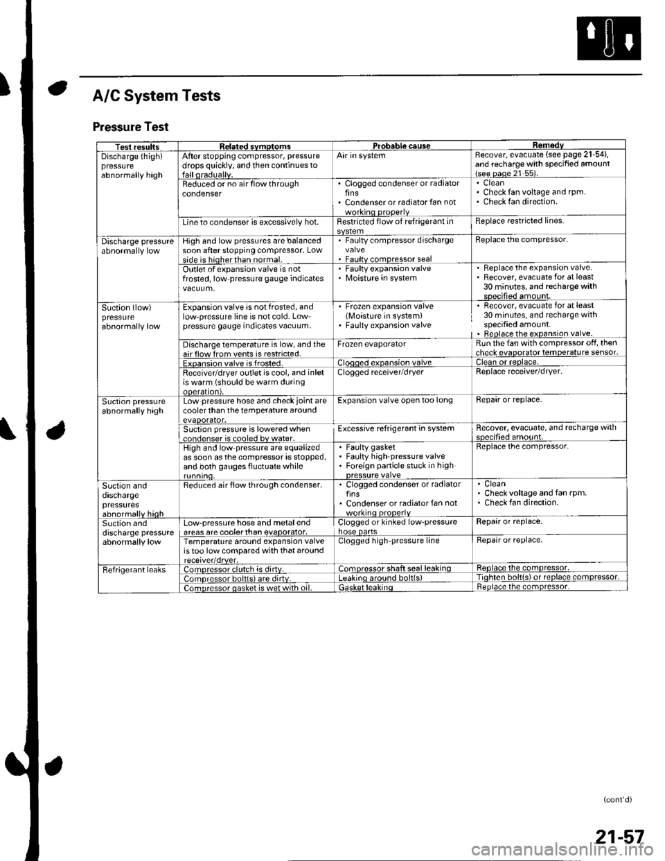
A/C System Tests
Pressure Test
Test resultssvmotom3DGaUSeDischarge (high)pressureabnormally high
After stopping compressor, pressure
drops quickly, and then continues toAir in systemRecover, evacuate (see page 21-54),and recharge with specified amount{see oaoe 21 55).
Beduced or no air flow throughcondenserClogged condenser or radiatorfinsCondenser or radiator fan not
CleanCheck fan voltage and rpm.Check fan direction.
Line to condenser is excessively hot.Restricted flow of refrigerant inReplace restricted lines.
Discharge pressureHigh and low pressures are balancedsoon after stopping compressor, Lowside is hioherthan normal.
. Faulty compressor dischargevalve. Faultv comoressor seal
Beplace the compressor.
Outlet of expansion valve is notfrosted, low pressure gauge indicatesFaulty expansion valveMoisture in system
. Replace the expansion valve.. Recover, evacuate for at least30 minutes, and recharge withsDecified amount.
Suction (low)pressureabnormally low
Expansion valve is not frosted, andlow-pressure line is not cold. Lowpressure gauge indicates vacuum,
' Frozen expansion valve(Moisture in system). Faulty expansion valve
Recover, evacuate for at least30 minutes, and recharge withspecified amount.Beplace the expansion valve.
Discharge temperature is low, and theair flow from vents is restricted.Frozen evaporatorRun the fan with compressor off, thencheck evaooratot temoerature sensor.
Exoansion valve is frosted.ean or reolace,
Receivetdryer outlet is cool, and inletis warm (should be warm duringooeralton),
Clogged receiver/dryerReplace receaver/dryer.
Suction pressureabnormally highLow pressure hose and check joint arecooler than the temperature aroundevaoorator,
Expansion valve open too longBepair or replace.
Suction pressure is lowered when..nrlenser is cooled bv water.Excessive refrigerant in systemRecover, evacuate, and recharge withqnp.ifie.lamo'rnr
High and low pressure are equalizedas soon asthecompressor is stopped,and both gauges fluctuate while
Faulty gasketFaulty high pressure valveForeign panicle stuck in high
Replace the compressor.
Suction anddaschargepressuresabnormallv hioh
Reduced air flow through condenser.. Clogged condenser or radiatorfins' Condenser or radiator fan notworkino orooerlv
CleanCheck voltage and fan rpm.Check fan direction.
Suction anddischarge pressureabnormally low
Low-pressure hose and metalendareas are coolerthan evaoorator,Clogged or kinked low-pressurehose oartsRepair or replace.
Temperature around expansion valveis too low compared with that aroundClogged high-pressure lineRepair or replace,
Fefrigerant leaks:omoressor clulch is dirtv.:omoressor shaft seal leakinqReolace the comDressor,
lomoressor bolt(s) are dirtv.no around bolt(s)Tiohten bolt{s) ot reolace comDressor,
;omDressor oasket is wet with oil.ietnoace the comoressor.
(cont'd)
21-57
Page 847 of 1139

Connectors and Harnesses
Engine Wire Harness
Camshaft position (CMP) sensorLllr sensorEC[,4 connector AECI/l connector BEngine coolant temperature (ECT)
sensorEngine oil pressure switchEVAP canister purge valveldle air control (lAC)valve
lgnition coil No. llgnition coil No. 2lgnition coil No. 3lgnition coil No. 4Iniector No. 1Inlector No.2Iniector No.3Iniector No. 4Intake air temperature {lAT) sensor
TDC sensorThrottle position (TP) sensorVehicle speed sensor (VSSI
VTC oil control solenoid valveVTEC oil pressure switchVTEC solenoid valvec 101
c102
233
242
Transmission housingLeft side of engineRight side ofengineUnder glove boxUnder glove boxLeft side of engine
Bight side oI engineLeft side of intake manifoldLeft side of intake manifoldMiddle of engine compartmentMiddle of engine compartmentMiddle of engine compartmentMiddle of engine compartmentMiddle of engine compartmentMiddle of engine compartmentMiddle of engine compartmentMiddle of engine companment
28
1845672524201912
811102729303
22
12333332222233
322220
Left side of intake manifoldLeft side of engineLeft side of intake manifoldTransmission housingRight side o{ engineRight side of engineRight side of engineUnder right side of dash
Front of engine companment
Front of engine compartment
ECM wire harness {see page22-321Starter subharness (see page22-15)Starter subharness (see page22 151
Connector to Harness Index (cont'dl
22-16
Page 874 of 1139

A/C Wire Harness
Connoctor or TerminalRelCavitiesLocationConnec'tstoNotesAir mix control motorBlower motorEvaporator temperature sensorMode control motorPowertransistorRecirculation control motorc851
c852
c853
I283411
6
5
52210
51
21
,]
Under maddle of dashUnder right side of dashUnder middle of dashUnder right side of dashUnder right side of dashUnder right side of dashUnder middle ol dash
Under middle ofdash
Under middle o{ dash
Engine compartment wireharness (see page 22-18)Dashboard wire harness A{see page 22 26iDashboard wire harness Alsee oaoe 22-261
22-43
Page 885 of 1139

Gauges
\-Component Location Index
PARKING BRAKE SWITCHpage 19-10
FUEL GAUGE SENDINGpage 11-156ENGINE OIL PRESSURE SWITCHpage 8-4
GAUGE ASSEMBLYSelJ-diaqnostic Procedure, page 22-56Gauqe dulb Replacement, page 22 63Rep6cement, page 22-64Coolant Temperature GaugeTroLrbleshooting, page 22'64
BRAKE FLUID LEVEL SWITCHpage 19-10VEHICLE SPEED SENSOR {VSS)Troubleshooting, page 22-65Beplacement, page 22-67
22-54
\
Page 1134 of 1139
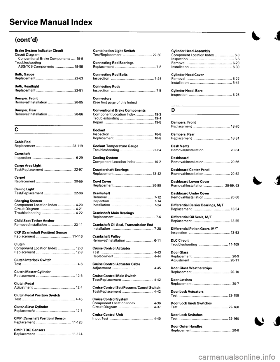
Service Manual Index
(cont'dl
Brake System Indicator CircuitCircuit DiagramConventional Brake Components..... 19-9TroubleshootingABS/TCS Components .... ....... ...... 19-55
Bulb, GeugeRep|acemenl................ .. ............2263
Bulb, HeadlightReplacement ......................................... 22-A1
Bumper, FrontRemoval/1nsra11ation ............................ 20 85
Bumper, RearRemoval/lnstallation... ... . .....20.86
Combination Light SwilchTesVReplacement ..............................22 80
Connecting Rod BearingsRep|acement...................... .......-....7-8
Connecting Rod Boltsf nspection ....................-.-.-.-.................... 7 -24
Connecting RodsInspection ........,,.,.,...,.,.,.,.,,,,.,,,.,.,.,.,.,.,.,.. 7 5
Connectors(See first page of this Index)
Conventional Brake Component3Component Location Index ................... 19'3Troub1eshootin9 ..................................... 19-4
Cylinder Head AssemblyComponent Location Index ..................... 6-3Inspection ................................................. 6 6Removal ..........&23Insta11alion .............................................. 6 39
Cylinder Head Cover8emova1 ..............-.-................................. 6-22Installation ..............................................6-41
Cylinder Head, BareInspecton..,.....,.
D
c
Cable ReelReplacement....................................... 23-1 19
CamshaftInspection .......................-...-................... 6-29
Cargo Area LightTesVRep1acement ................................ 22-97
CarpetReplacement.....-...-..... ... ......-.20-55
Ceiling Light-estrReplacement ................................ 22.96
Charging SystemComponent Location Index................... 4-20Circuit Diagram ...................................... 4-21
19-8
CoolantInspection .................. ..... .. 106Replacement................. ... . .. 10 6
Coolant Temperature Gat|geTroub1eshootin9................................... 22 64
Cooling SyslemComponent Location Index................... 10-2
Countershaft BearingsReplacement............... ..................... 13-42
Cowl CoverReplacement............... .. ..... ....20-95
CrankshaftRemoval .................................................. 7 -12
Repair ..................
Inspec(on,,,,,........1 14
Dampers. FrontReplacement................ ..................... 18 20
Oampers, RearRep1acement......................................... 18-34
Dash VentsBemoval/lnstallation .-.......................... 20-64
DashboardBemoval/1nsta11ation ............................ 20-66
Oashboard Center PanelRemoval/1nstaf 1ation ............................ 20 62
Dashboard Lower CoverRemoval/lnstallation ...................... 20-59, 63
Dashboard Under CoverRemoval/lnstallation ............................ 20 60
Diff erential Carrier Bearings, M/TRep1acement,,......,...,...,.,.,,,.,.,,,........,.,. 13-54
Ditferential Oil Seals, M/T8ep1acement......................................... 13-55
Differential Pinion Gears, M/TInspection .,....-,.,,,.,..,.-,.,.........,.,.,,, 13 53
OLC CircuitTroubleshooting ................................ 1 1-109
Door GlassRep1acement.,.,,,,,,,,,,,.,,,,,,,,,,.,.,.,.,.,,,,,,.,, 20-9Adjustment. .. .....................20-11
Door Glass WeathelstripsReplacement .............-.. . . . ..........-......20 10
Door LatchesReplacement ..........-.-.............................. 20-7
Door Lock ActuatorsTest ...................................................... 22-154
Door Lock Knob SwitchesTest -......... . . . - . . . . . . . . ......22-160
Door Lock SwitchesTest ........... ............................ ............. 22-160
Door Outer HandlesRep1acemen1 ........................................... 20-6
3
Child Seat Tether AnchorRemoval/lnstaf lat;on .. ........................ 23 11
CKP (Crankshaft Position) SonsorReplacement....................................... 1 1-116
ClutchComponentLocation 1ndex................... 12-3Rep1acemen1........................................... 12-9
Clutch InteYlock SwitchTest.....-........-...-............. ...---.-.......4-6
Clutch Master CylinderReplacement........................................... 12 5
clutch PedalAdjustment ............................................. 12 4
Clutch Pedal Position SwitchTest.,.,,,,,.,,,.,.,,,,,,.,.,,,,,,,,,.,,,,,.. ......445
lnstallation.................. . ..... .....1-24
Crankshalt Main BearingsReplacement........-.-.................................. 7-6
CrankshaftOil Seal,Transmission End1nstanation .............................................. 7 28
Crankshafl PulleyRemoval/lnstallation -..................-.......... 6-1 1
Cruise Control Actuator
Troubleshooting
Clutch Slave CylindorBeplacemeit...
...................... 4-43
.......4-22
Test
12-1
RepIacement........................................... 4-44
Cruise Control Actuator CableAdjustment ............................................. 4 45
Cruise Control Main SwitchTesVRep1acement .................................. 4 42
Cruise Control Set/Resume/Cancel SwitchTesVRep1acement .................................. 4 42
Cruise Control SystomComponent Localion Inde\................... 4-36Circuit Diagram ....-................................. 4 37
Cruise Control UnitInputTest.............................. .. ...4,40CMP {Camshaft Positionl Senso]Replacement....-...-.............................. 1 1-128
CMP (TDC) SensorsReplacement............-.......................... 1 1 1 14