2002 HONDA CIVIC ECO mode
[x] Cancel search: ECO modePage 829 of 1139
Heating and Air Conditioning
A/C System Tests (cont'd)
1.
Performance Test
Air conditioning refrigerant or lubricant vapor
can irritate your eyes, nose, or throar.
Be carefulwhen connecting service equipment.
Do not breathe refrigerant or vapor.
The performance test will help determine if the air
conditioner system is operating within specifications.
Use only service equipment that is U.L.-listed and is
cenified to meet the requirements of SAE J2210 toremove HFC-134a (R-134alfrom the air conditioning
system.
lf accidental system discharge occurs, ventilate the
work area before resuming service
R-134a service equipment or vehicle air conditioning
systems should not be pressure tested or leak testedwith compressed air.
Additional health and safety information may be
obtained from the refrigerant and lubricant
manufacturers.
Connect a R-134a refrigerant recover/recycling/
charging station to the high-pressure service port
and the low-pressure service port, following the
equipment manufacturer's instructions.
Determine the relative humidity and air
Iemperaru re.
' Compressed air mixed with R-134a forms a
combustible vapor.. The vapor can burn or explode causing serious
Injury.. Never use compressed air to pressure test
R-134a service equipment or vehicle air
conditioning systems.
21-58
4.
Open the glove box. Remove both glove box stops,
then let the glove box hang down (see page 20-63).
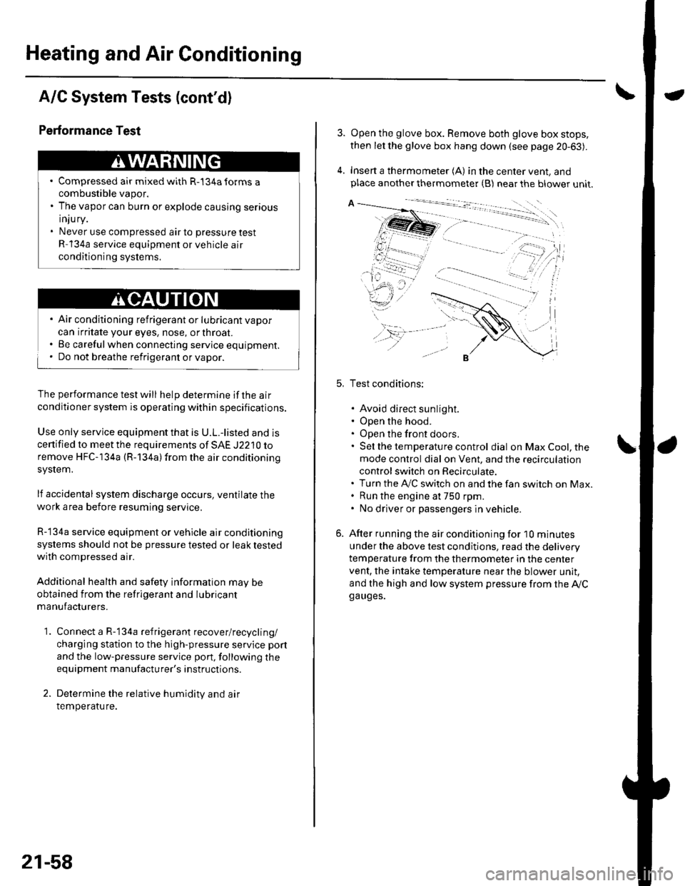
Insert a thermometer (A) in the center vent, andplace another thermometer {B) near the blower unit.
Test conditions:
. Avoid direct sunlight.. Open the hood.. Open the front doors.. Sel the temperature control dial on Max Cool, the
mode control dial on Vent, and the recirculation
control switch on Recirculate.. Turn the A,/C switch on and the fan switch on Max.. Run the engine at 750 rpm.. No driver or passengers in vehicle.
After running the air conditioning for I0 minutes
under the above test conditjons, read the delivery
temperature from the thermometer in the center
vent, the intake temperature near the blower unit,
and the high and low system pressure from the Ay'Cga uges.
Page 837 of 1139

Body Electrical
General Troubleshooting Information (cont'dl
Five-step Troubleshooting
'1. Verify The Complaint
Turn on allthe components in the problem circuit
to verify the customer complaint. Note the
symptoms. Do not begin disassembly or testing
until you have narrowed down the problem area.
2. Analyze The Schematic
Look up the schematic for the problem circuit.
Determine how the circuit is supposed to work by
tracing the current paths from the power feed
through the circuit components to ground. lf
several circuits fail at the same time, the fuse or
ground is a Iikely cause.
Based on the symptoms and your understanding of
the circuit operation, identify one or more possible
causes of the problem.
3. lsolate The Problem By Testing The Circuit
Make circuit tests to check the diagnosis you made
in step 2. Keep in mind that a logical, simple
procedure is the key to efficient troubleshooting.
Test for the most likely cause of failure first, Try to
make tests at points that are easily accessible.
4. Fix The Problem
Once the specific problem is identified. make the
repair. Be sure to use proper tools and safe
proceoures.
5. Make Sure The Circuit Works
Turn on all components in the repaired circuit in all
modes to make sure you've fixed the entire
problem. lf the problem was a blown fuse, be sure
to test all of the circuits on the fuse. Make sure no
new problems turn up and the original problem
does not recur.
22-6
Wire Color Codes
The following abbreviations are used to identify wire
colors in the circuit schematics:
wHT....................,.,.............
YEL......................,,.......,......
B1K......................................
BLU ....,................................
GRN.....................................
RED ....................................,
oRN.....................................
PNK..........................,..........
BRN.....................................
GRY....................................,
PUR.....................................
1T81U..........................,.....
1TGRN...........................,...
White
Yellow
Black
Blue
Green
Red
Orange
Pink
Brown
Gray
Purple
Light Blue
Light Green
The wire insulation has one color or one color with
another color stripe. The second color is the stripe.
Page 1002 of 1139
ISystem Descriptions
The Multiplex Control System has four internal
functions:. Multiplexing (send multiple signals over sharedwtres). Wake up/sleep (runs at full power only on demand toreduce battery draw). Fail-safe (fixes or ignores faulty signals). Self-diagnosis (Mode 1 for the system, Mode 2 for
input lines)
The system controls the function of these circuits:. Entry lightcontrol (ignition key lightandceiting light). Wiper/washer intermittent wipe and park functions. Keyless/power door lock. Meter assembly, temperature gauge, and indicator
lights. HVAC (compressor and fan control). Key-in reminder. Headlight reminder. Seatbelt reminder
JI
/ar
22-171
Multiplex Communication
To reduce the number of wire harnesses, digital signals
are sent via shared multiplex communication linesrather than sending normal electrical signals throughindividual wires.. The input signals from each switch are converted todigital signals at the central processing unit (CpU).. The digital signalsaresentfromthetransmitting unitto the receiving unit as serial signals.. The transmitted signal is converted to a switch signalat the receiving unit, and it operates the related
component or monitors a swltch.. There are exclusive communicalion lines between
the ECM, the gauge assembly, and the under,dash
fuse/relay box.
Wake-up and Sleep
The multiplex control system has "wake-up" and"sleep" functions to decrease parasitic draw on the
battery when the ignition switch is OFF.. ln the sleep mode, the multiplex control unit stops
functioning (communication and CPU control) when it
is not necessary for the system to operate.. As soon as any operation is requested (for example, adoor is unlocked), the related control unit in the sleep
mode immediately wakes up and begins to function.. When the ignition switch is turned OFF, and the
driver's or front passenger's door is opened, then
closed, there is about a 10 second delay before the
control unit goes from the wake-up mode to the sleepmode.. lf any door is open, the sleep mode will not function.. lf a key is in the ignition switch, the sleep mode will
not function.. When in sleep mode, the draw is reduced from
70 80 mA to less than 10 mA.
Fail-safe
To prevent improper operation, the multiplex controlsystem has a fail-safe function. In the fail-safe mode,
the output signal js fixed when any part of the systemmalfunctions (for example a faulty control unit orcommunication line).
Each control unit has a hardware fail-safe function thatfixes the output signal when there is any CPUmalfunction, and a software fail-safe function thatignores the signal from the malfunctioning control unitand allows the system to operate normally.
Page 1003 of 1139
Multiplex Control System
Troubleshooting
Mode 1 Tset
1. Remove the driver's dashboard lower cover {see
page 20-59).
2. Check the No. 9 ( 10A) fuse in the under-hood fuse/
relay box and the No. 10 (7.5A) fuse in the under-
dash fuse/relay box.
Are the fuses OK?
YES-Go to step 2.
NO-Find and repairthe cause ofthe blown fuse.!
3. Turn the ignition switch ON (ll).lf the driver's
seatbelt is unbuckled the seat belt reminder will
chime 6 times.
4. Set the ceiling light to the center position and close
allthe doors.
5. Connect the specialtoolto the multiplex inspection
conneclor.
6. After about 5 seconds the spotlight and ceiling light
should come on for 2 seconds, go out, then blink on
for 0.2 second to show the system is now in mode
1.
Did the spotlight and ceiling light indicate mode
1?
YES-Go to step 8.
NO Go to step 7.
22-172
-
7. Check for continuity between terminal 4ofthe
under-dash fuse/relay box connector J and body
ground.
ls there continuity?
YES Replace the under-dash fuse/relay box.l
NO - Repair the open in the wire.lf the wire is ok,
repair G301.1
8. lf ther are any DTCS present, the spotlight and
ceiling light will blink to indicate the DTC(S). lf more
than one DTC is present, the DTCS will be displayed
in ascending order, lf there are no DTCS the
spotlight and ceiling light will not blink again after
the mode 1 indication.
Are there any DTCg?
YES Go to step 9.
NO Go to the Mode 2 test.
9. Troubleshoot the DTC(S) in the order indicated
using the following charts.
lf a faulty control unit is suspected, substitute it
with a known food part and recheck for DTCS,
. lf the DTC(s) isstill present. go to the next step
listed for the DTC.. lf the DTC(S) is no longer present replace the
original part.
Page 1038 of 1139
ISystem Description
SRS Components
Airbags
The SRS is a safety device which, when used with the seat belt, is designed to help protect the driver and frontpassenger in a frontal impact exceeding a certain set limit. The system consists ofthe SRS unit, including safingsensor and impact sensor (A), the cable reel (B), the driver's airbag (C), the front passenger,s airbag (D). seat belttensioners (l), seat belt buckle tensioners (J), and front impact sensors (K).
Since the driver's and front passenger's airbags use the same sensors, both normally inflate at the same ttme.However, it is possible for only one airbag to inflate. This can occur when the severity of a collision is at the margin, orthreshold, that determines whether or not the airbags will deploy. In such cases, the seat belt will provide sufficientprotection, and the supplemental protection offered by the airbag would be mininal.
Side Airbags
The side airbags (E) are in each front seat-back. They help protect the upper torso of the driver or front seat passenger
during a moderate to severe side impact. Side impact sensors (F) in each door sill and in the SRS unit detect such animpact and instantly inflate the driver's or the passenger's side airbag. Only one side airbag will deploy during a sideimpacl. lf the impact is on the passenger's side, the passenger's side airbag will deploy even if there is no passenger.
Seat Belt and Seat Belt Buckle Tensioners
The seat belt and seat belt buckle tensioners are linked with the SRS airbags to further increase the effectiveness ofthe seat belt. ln a front-end collision, the tensioners instantly retract the belt and buckle firmly to secure the occupantsin their seats.
OPDS
The side airbag system also includes an occupant position detection system (OpDS). This system consists of sensors(G)and an OPDS unit (H) in the front passenger's seat-back. The OPDS unit sends occupant heighl and position data tothe SRS unit. lf the OPDS unit determines that the front passenger is of small stature (for example, a child) and thefront passenger is leaning into the side airbag deployment path, the SRS unit will automatically disable the passenger'sside airbag. The SRS unit will also disable the airbag when the OPDS detects certain obiects on the seat. When theside airbag is disabled, the side airbag cutoff indicator on the instrument panel alerts the driver that the passenger'sside airbag will not deploy in a side impact. When the object is removed, or the passenger sits upright, the side airbagcutoff indicator will go off after a few seconds, alerting the driver that the passenger's side airbag will deploy in a sideimDact.
(cont'd)
I
23-31
Page 1114 of 1139
JI
I
The SRS lndicator Stays On When ln "SCS"
Menu Method
NOTE:. lf you cannot retrieve DTCSwith the PGM Tester
using the SRS menu method. retrieve the flash codeswith the Tester in SCS mode {see page 23-24|,.. A new SRS unit must sense the entire system is OK
before completing its initial self-test. The most
common cause of an incomplete self-test is the
failure to replace all deployed parts after a collision,
in particular, seat belt tensioners and seat belt buckletenstoners.. An incomplete self-test prevents the PGM Tester fromretrieving DTCS, although flash codes are available in
the Tester's SCS mode.
1 . Erase the DTC memory using the MES connector(see page 23-26).
Does the SRS indicator go off while you are
erasing the DTC memory?
YES-Go to step 42.
NO Go to step 2.
Check the No. '13 { 10A) fuse in the under-dash
fuse/relay box.
lsthe f use OK?
YES--Go to step 19.
NO Go to step 3.
Replacethe No. 13 (10A) fuse.
Turn the ignition switch ON (ll), and wait for 30
seconds. Then turn the ignition switch OFF.
Check rhe No. 13 (10A) fuse.
ls the f use OK?
YES The system is OK at this time.I
NO Go to step 6.
3.
I
6. Replace the No. 13 (10A) fuse.
7. Turn the ignition switch OFF. Disconnect the
battery negative cable, and wait for 3 minutes.
8. Disconnect the driver's airbag 4P connector (see
step 2 on page 23-21).
9. Disconnect the front passenger's airbag 4P
connector (see step 3 on page 23,21).
10. Disconnect both seat belt tensioner 2P connectors(see step 5 on page 23-221.
'11. DisconnectSRS unitconnectorA{18P)fromthe
SRS unit (see step 7 on page 23-22],.
'12. Reconnect the battery negative cable.
13. Turn the ignition switch ON (ll), and wait for 30
seconds. Then turn the ignition switch OFF.
14. Checkthe No. 13 ('10A) fuse.
ls the f use OK?
YES-Short to ground in the SRS unit; replace the
SRS unit (see page 23-122).a
NO Go to step 15.
15. Replace the No. 13 (10A) fuse.
{cont'd)
23-107