2002 HONDA CIVIC dtc
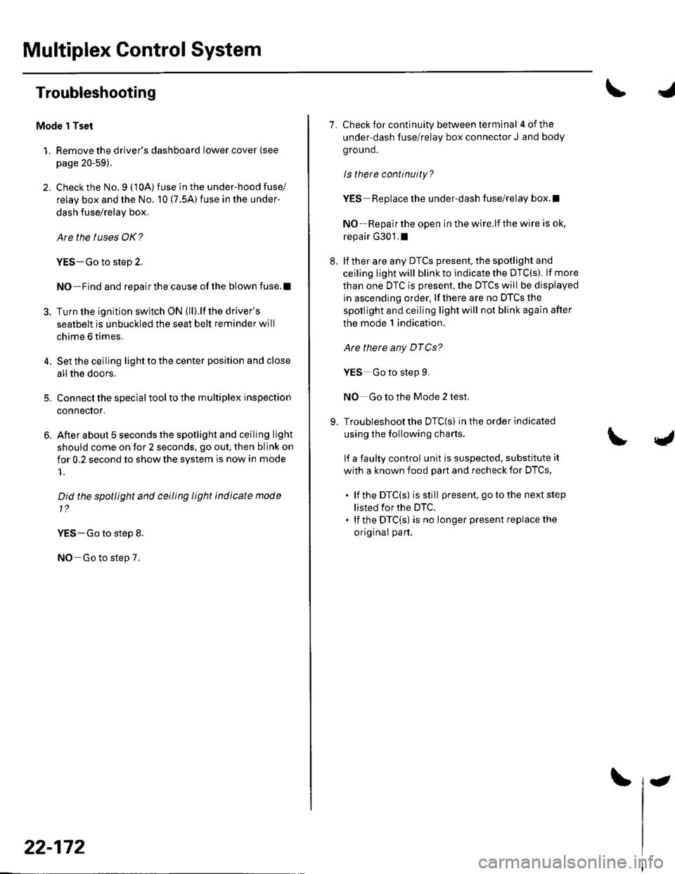
[x] Cancel search: dtcPage 794 of 1139

DTC 14: An Open in the Evaporator
Temperature Sensor Circuit
1. Remove the evaporator temperature sensor (see
page 21-37).
2. Measure the resistance between the No. l and
No. 2 terminals of the evaporator temperature
sensor.x Dip the sensor in ice water, and measure
resistance. Then pour hot water on the sensor, and
check for change in resistance.
EVAPORA
RESISTANCEk0
TOR TEMPERATURE SENSOR
t-lll#l
ll,l,llI UT-TU I---r---T--
t^11c))-l\9/
50 6810 20
TEMPERATURE
ls the tesistance within the specifications shown
on the graph?
YES-Go to step 3.
NO Replace the evaporator temperature
sensor.I
3. Disconnect heater control panel connector B {22P).
86'F30 'c
Terminal side of male terminals
4. Check for continuity between the No. 7 terminal of
heater control panel connector B (22P) and the
No. 1 terminal of the evaporalor temperature
sensor 2P connector.
HEATER CONTROL PANEL CONNECTOR B {22P)Wire side of female terminals
EVAPORATOR TEMPERATURE SENSOR 2P CONNECTORWire side of female terminals
ls there continuity?
YES Go to step 5.
NO Repair open in the wire between the heater
control panel and the evaporator temperature
sensor.I
5. Disconnect heater control panel connector A (14P).
(cont'd)
21-23
Page 795 of 1139

Heating and Air Gonditioning
\
DTC Troubleshooting {cont'd)
6. Check for continuity between the No. 2 terminal of
heater control panel connector A (14P) and the
No, 2 terminal of the evaporalor temperature
sensor 2P connector.
HEATER CONTROL PANEL CONNECTOR A {14PIWire side of female terminals
LT GRN
EVAFORATOR TEMPERATURE SENSOR 2P CONNECTORWire side of female terminals
ls there continuity?
YES-Check for loose wires or Door connections at
heater control panel connector A ('l4P) and B l22Pl
and at the evaporator temperature sensor 2P
connector. lf the connections are good, substitute a
known-good heater control panel, and recheck. lf
the symptom/indication goes away, replace the
original heater control panel.l
NO Reoair ooen in the wire between the heater
control panel and the evaporator temperature
sensor.I
21-24
4.
DTC 15: A Short in the Evaporator
Temperature Sensor Circuit
1. Remove the evaporator temperature sensor (see
page 21-37).
2. Test the evaporator temperature sensor (see page
21-37 J.
ls the resistance within the specifications shown
on the graph?
YES Go to step 3.
NO Replace the evaporator temperature
sensor. !
Disconnect heater control panel connector B l22Pl.
Check for continuity between the No. 7 terminal of
heater control panel connector B {22P) and body
ground.
HEATER CONTROL PANEL CONNECTOR B (22P)
Wire side of female terminals
ls there continuity?
YES Repair short to body ground in the wire
betvveen the heater control panel and the
evaporator temperature sensor. I
NO-Substitute a known-good heater control panel,
and recheck. lf the symptom/indication goes away,
replace the original heater control panel.I
Page 893 of 1139

Gauges
\"Circuit Diagram (cont'dl
CoME|NAT|ON tMf,tOBtUZEnLtctlTswtTclt @l TRoLUN|I ftCtIVER
GRNIfiED
I\""'7
VLEFTTUNSIGI'IALII'{DICATORGAUGIASSEi|BLY LTCHTS
\,HIGHSEAM -|. IMMOBITIZERltDtcATon r/: tilucaToB
f,il vll9i,]
22-62
J
Page 895 of 1139

Gauges
2.
3.
Gauge Assembly Replacement
1.Remove the instrument panel (see page 20-59),
then remove the upper column cover {see page 17-
Place a clean shop towel (A) under the gauge
assembly to prevent scratching the steering
colum n or dash panel.
Remove the screws from the gauge assembly (B).
Disconnect the connectors (C), and remove thegauge assemDry.
Installthe gauge assembly in the reverse order of
removal.
Coolant Temperature Gauge
Troubleshooting
Before testing, check the No. I { 10A) fuse in the under-
hood fuse/relay box and the No. '10 (7.5A) fuse in the
under dash fuse/relay box.
1. Start the engine, and check the malfunction
indicator lamp (MlL).
Does the MIL come on?
YES- Troubleshoot the cause of the ECM DTC (see
page 1 1-57), and recheck.
NO-Go to step 2.
2. Check for a multiplex control unit DTC (see page
22,168).
ls a DTC ind icated?
YES Troubleshooting the cause of the multiplex
control unit DTC {see page 22-168), and recheck.
NO Go to step 3.
3. Do the communication line check with the self-
diagnosis procedure (see page 22-56).
ls the word "Error" indicated on the odo/ttip
d isplay ?
YES The gauge cannot receive the signal from the
multiplex control unit and the ECI\,4. Check for an
open in the WHT/GRN wire (gauge connector
terminal B 13). lf no open is found, go to step 5.
NO Go to step 4.
4. Do the gauge drive circuit check with the self-
diagnosis procedure (see page 22-56).
Does the temperature gauge needle sweep lrom
the minimum position to the maximum, then tetutn
to the minimum position?
YES Go to step 5.
NO Replace the gauge assembly.l
5. Substitute a known-good ECM and recheck.
Did the symptom/ ind ication go away?
YES Replace the ECM.
NO Substitute a known good gauge assembly. lf
the symptom/indication goes away, replace thegauge assembly.l
4.
22-64
Page 996 of 1139

)
I
Troubleshooting
Before troubleshooting the immobilizer system,
troubleshoot any EClvl Diagnostic Trouble Codes (DTCS)
(see page 11-3), and make sure the ECM has no
malfunction.
Note these items before trou bleshooting:
. Due to the action of the immobilizer system, the
engine takes slightly more time to start than on a
vehicle without an immobilizer system.. When the system is normal, and the proper key is
inserted, the indicator light comes on for 2 seconds,
then it will go off.. If the indicatorstartsto blink after 2 seconds, or if the
engine does not start. remove any other immobilizer
keys or large key fobs on the key ring, then repeat the
starting procedure.
lf the engine still does not start, continue with thisprocedure.
1. Turn the ignition switch ON {ll) with proper key.
2. Check to see if the immobilizer indicator light
comes on.
Does the indicator light blink?
YES Disconnect the 7P connector from the
immobilizer control unit-receiver, then go to step 9.
NO Check for these problems, then go to step 3.
. Blown No. 9 (10A)fuse in the under-hood
fuse/relay box.I. An open in the wire between the gauge assembly
and the immobilizer control unit-receiver.l. A faulty immobilizer indicator light,I. An open in the wire between the gauge assembly
and the under-hood fuse/relay box.l
Remove the driver's dashboard lower cover (see
page 20-59).
Remove the steering column lower cover (see page
11-9).
l
-_--t
22-165
5. Disconnect the 7P connector (A)from the
immobilizer control unit-receiver (B),
Check for voltage between the immobilizer control
unit-receiver 7P connector No. 7 terminal and body
ground.
ls there battery voltage?
YES-Go to step 7.
NO Check for these problems;
. Blown No. 9 {10A)fuse in the under-hood fuse/
relay box.l. An open in the WHT/RED wire.l
Check for voltage between the immobilizer control
unit-receiver 7P connector No. 6 terminal and bodyground with the ignition switch ON {ll).
ls there battery voltage?
YES- Go to step 8.
NO Check for these problems:
. Blown No.6 (15A)fuse in the under-hood
fuse/relay box,I. Faulty PGM-Fl main relay 1,t. An open in the YEUBLK wire.l
1.
(cont'd)
Page 1003 of 1139

Multiplex Control System
Troubleshooting
Mode 1 Tset
1. Remove the driver's dashboard lower cover {see
page 20-59).
2. Check the No. 9 ( 10A) fuse in the under-hood fuse/
relay box and the No. 10 (7.5A) fuse in the under-
dash fuse/relay box.
Are the fuses OK?
YES-Go to step 2.
NO-Find and repairthe cause ofthe blown fuse.!
3. Turn the ignition switch ON (ll).lf the driver's
seatbelt is unbuckled the seat belt reminder will
chime 6 times.
4. Set the ceiling light to the center position and close
allthe doors.
5. Connect the specialtoolto the multiplex inspection
conneclor.
6. After about 5 seconds the spotlight and ceiling light
should come on for 2 seconds, go out, then blink on
for 0.2 second to show the system is now in mode
1.
Did the spotlight and ceiling light indicate mode
1?
YES-Go to step 8.
NO Go to step 7.
22-172
-
7. Check for continuity between terminal 4ofthe
under-dash fuse/relay box connector J and body
ground.
ls there continuity?
YES Replace the under-dash fuse/relay box.l
NO - Repair the open in the wire.lf the wire is ok,
repair G301.1
8. lf ther are any DTCS present, the spotlight and
ceiling light will blink to indicate the DTC(S). lf more
than one DTC is present, the DTCS will be displayed
in ascending order, lf there are no DTCS the
spotlight and ceiling light will not blink again after
the mode 1 indication.
Are there any DTCg?
YES Go to step 9.
NO Go to the Mode 2 test.
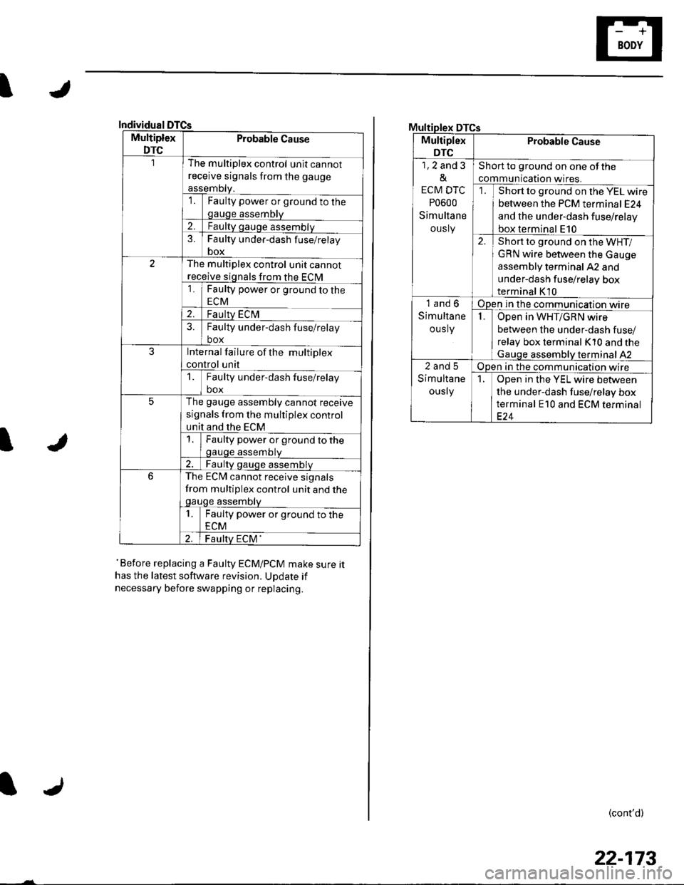
9. Troubleshoot the DTC(S) in the order indicated
using the following charts.
lf a faulty control unit is suspected, substitute it
with a known food part and recheck for DTCS,
. lf the DTC(s) isstill present. go to the next step
listed for the DTC.. lf the DTC(S) is no longer present replace the
original part.
Page 1004 of 1139

I
Individual
Multiplex
DTC
Probable Cause
The multiplex control unit cannot
receive signals from the gauge
assemDty.'lFaulty power or ground to thegauge assembly
2.Faulty gauge assemblv
3.Faulty under-dash f use/relay
box
The multiplex control unit cannot
receive signals from the ECM
1Faulty power or ground to the
ECM
2.Faulty ECM?Faulty under-dash fuse/relay
box
JInternal failure of the multiplex
control unit
1Faulty under-dash fuse/relay
box
5The gauge assembly cannot receive
signals from the multiplex control
unit and the ECM
Faulty power or ground to thegauge assembtv
Faulty qauge assemblv
6The ECM cannot receive signals
from multiplex control unit and thegauge assembty
1Faulty power or ground to the
ECM
Faulty ECM'
I
'Before replacing a Faulty ECM/PCM make sure ithas the latest software revision. UDdate if
necessary before swapping or replacing.
DTCs
Multiplex
DTC
Probable Cause
1,2 and 3
&
ECM DTC
P0600
Simultane
ously
Short to ground on one of the
communication wires.
Short to ground on the YEL wire
between the PCM terminal E24
and the under-dash fuse/relay
box terminal E10
2.Short to ground on the WHT/
GRN wire between the Gauge
assembly terminal A2 and
under-dash fuse/relay box
terminal K10
1and6
Simultane
ous ly
Open in the communication wire
IOpen in WHT/GRN wire
between the under-dash fuse/
relay box terminal K10 and the
Gauqe assemblV terminal 42
2and5
Simultane
ously
Open in the communication wire
1Open in the YEL wire between
the under-dash fuse/relay box
terminal E10 and ECM terminal
(cont'd)
22-173
Page 1009 of 1139

I
I
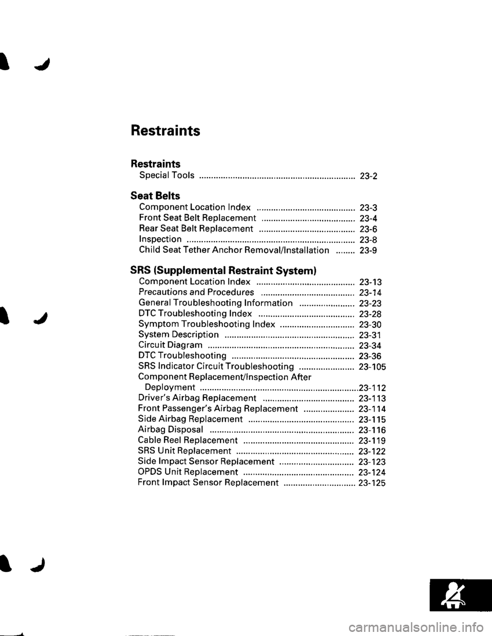
Restraints
Restraints
Special Tools ............. 23-2
Seat Belts
Component Location Index ......................................... 23-3
Front Seat Belt Replacement ....................................... 23-4
Rear Seat Belt Replacement ........................................ 23-6
Inspection .................. 23-8
Child Seat Tether Anchor Removal/lnstallation ........ 23-9
SRS (Supplemental Restraint Systeml
Component Location Index ......................................... 23-13
Precautions and Procedures ,,.,......... 23-14
General Troubleshooting Information ....................... 23-23
DTC Troubleshooting Index .............. 23-28
Symptom Troubleshooting Index ............................... 23-30
System Description ................. ........... 23-31
Circuit Diagram ......... 23-34
DTC Troubleshooting ............... .......... 23-36
SRS Indicator Circuit Troubleshooting ....................... 23-105
Component R e place me n(/ln s pect io n After
Deployment ..............23-112
Driver's Airbag Replacement ............ 23-113
Front Passenger's Airbag Replacement ..................... 23-1 14
Side Airbag Replacement .................. 23-115
Airbag Disposal ....................... ........... 23-116
Cable Reel Replacement .................... 23-119
SRS Unit Repfacement ....................... 23-122
Side fmpact Sensor Replacement ..........,.................... 23-123
OPDS Unit Replacement .................... 23-124
Front fmpact Sensor Replacement .............................. 23-125