2002 FORD MUSTANG cooling
[x] Cancel search: coolingPage 17 of 264

Never remove the coolant reservoir cap
while the engine is running or hot. Steam
and scalding liquid from a hot cooling system can
burn you badly.
This gauge indicates the temperature of the engine
coolant, not the coolant level. If the coolant is not at
its proper level the gauge indication will not be
accurate.
Engine oil pressure gauge
Indicates engine oil
pressure. At normal
operating temperature,
the needle will be in
the normal range (the area between the ªLº and
ªHº); if the needle goes below the normal range,
stop the vehicle as soon as safely possible and
switch off the engine immediately. Check the oil
level. Add oil if needed (refer toEngine oilin the
Maintenance and specificationschapter). If the oil
level is correct, have your vehicle checked at your
dealership or by a qualified technician.
Battery voltage gauge
Indicates battery
voltage. If the pointer
moves and stays
outside the normal
operating range (as indicated by the arrows), have
the vehicle's electrical system checked as soon as
possible.
LH
LH
Instrument Cluster
17
Page 169 of 264

The high-current fuses are coded as follows.
Fuse/Relay
LocationFuse Amp
RatingPower Distribution Box
Description
Relay 1 Ð Fog lamp interrupt
Relay 2 Ð Int. wiper
Relay 3 Ð Wiper HI/LO
Relay 4 Ð Starter
Relay 5 Ð Fog lamps
1 50A** (4.6L),
30A CB
(3.8L)Electric cooling fan motor
2 30A** Headlamps
3 40A** Starter motor relay, Ignition
switch
4 40A** Ignition switch
5 40A** Ignition switch
6 40A** Instrument cluster, PCM
7 30A** Secondary air injection
(3.8L only)
8 50A** ABS module
9 20A** Auxiliary power point
10 30A** Parklamps
5
RELAY4
RELAY3
RELAY2
RELAY1
RELAY
12
MAXI
29
DIODE28
CB27
MAXI26
MAXI25
MAXI23
MINI
24
MINI
21
MINI
22
MINI
19
MINI17
MINI18
MINI15
MINI13
MINI
14
MINI16
MINI20
MINI
11
MAXI10
MAXI9
MAXI8
MAXI7
MAXI6
MAXI5
MAXI4
MAXI3
MAXI2
MAXI1
MAXI
SEE OWNERS MANUAL CONSULTER LA GUIDE
Roadside Emergencies
169
Page 175 of 264

Do not attempt to push-start your vehicle.
Automatic transmissions do not have
push-start capability; also, the catalytic
conveter may become damaged.
Preparing your vehicle
When the battery is disconnected or a new battery is
installed, the transmission must relearn its adaptive
strategy. As a result of this, the transmission may
shift firmly. This operation is considered normal and
will not effect function or durability of the
transmission. Over time, the adaptive learning
process will fully update transmission operation to
its optimum shift feel.
1.
Use only a 12±volt supply to start your vehicle.
2.Do not disconnect the battery of the disabled vehicle
as this could damage the vehicle's electrical system.
3.Park the booster vehicle close to the hood of the
disabled vehicle making sure the two vehiclesdo not
touch. Set the parking brake on both vehicles and stay
clear of the engine cooling fan and other moving parts.
4. Check all battery terminals and remove any
excessive corrosion before you attach the battery
cables. Ensure the vent caps are tight and level.
5. Turn the heater fan on in both vehicles to protect
any electrical surges. Turn all other accessories off.
Connecting the jumper cables
1. Connect the positive (+) booster cable to the
positive (+) terminal of the discharged battery.
Note:In the illustrations,lightning boltsare used
to designate the assisting (boosting) battery.
+–+–
Roadside Emergencies
175
Page 202 of 264

2. Turn off the engine and remove the key.
3. Block the wheels to prevent the vehicle from
moving unexpectedly.
²Manual transmission:
1. Set the parking brake.
2. Depress the clutch and place the gearshift in 1
(First).
3. Turn off the engine and remove the key.
4. Block the wheels to prevent the vehicle from
moving unexpectedly.
Working with the engine on
²Automatic transmission:
1. Set the parking brake and ensure the gearshift is
securely latched in P (Park).
2. Block the wheels to prevent the vehicle from
moving unexpectedly.
Note:Do not start your engine with the air cleaner
removed and do not remove it while the engine is
running.
²Manual transmission:
1. Set the parking brake, depress the clutch and
place the gearshift in neutral.
2. Block the wheels to prevent the vehicle from
moving unexpectedly.
Note:Do not start your engine with the air cleaner
removed and do not remove it while the engine is
running.
The cooling fan is automatic and may come
on at any time. Always disconnect the
negative terminal of the battery before working
near the fan.
Maintenance and Specifications
202
Page 206 of 264

WINDSHIELD WASHER FLUID
Washer fluid
Check the washer fluid
whenever you stop for
fuel. The reservoir is
highlighted with a
symbol.
If the level is low, add
enough fluid to fill the
reservoir. In very cold
weather, do not fill the
reservoir all the way.
Only use a washer fluid that meets Ford
specification ESR-M17P5±A. Refer toLubricant
specificationsin this chapter.
State or local regulations on volatile organic
compounds may restrict the use of methanol, a
common windshield washer antifreeze additive.
Washer fluids containing non-methanol antifreeze
agents should be used only if they provide cold
weather protection without damaging the vehicle's
paint finish, wiper blades or washer system.
Note:Do not put washer fluid in the engine coolant
reservoir. Washer fluid placed in the cooling system
may harm engine and cooling system components.
ENGINE OIL
Checking the engine oil
Refer to the scheduled maintenance guide for the
appropriate intervals for checking the engine oil.
1. Make sure the vehicle is on level ground.
2. Turn the engine off and wait 5 to 10 minutes for
the oil to drain into the oil pan.
3. Set the parking brake and ensure the gearshift is
securely latched in P (Park) (automatic
transmissions) or 1 (First) (manual transmissions).
Maintenance and Specifications
206
Page 215 of 264

washer fluid outside of its specified function and
vehicle location.
Adding engine coolant
When adding coolant, make sure it is a 50/50
mixture of engine coolant and distilled water. Add
the mixture to the coolant reservoir,when the
engine is cool, until the appropriate fill level is
obtained.
Do not add engine coolant when the engine
is hot. Steam and scalding liquids released
from a hot cooling system can burn you badly.
Also, you can be burned if you spill coolant on hot
engine parts.
Do not put engine coolant in the windshield
washer fluid container. If sprayed on the
windshield, engine coolant could make it difficult
to see through the windshield.
The cooling system in your vehicle is filled with
either green-colored Motorcraft Premium Engine
Coolant meeting Ford specification ESE-M97B44±A
or yellow-colored Motorcraft Premium Gold Engine
Coolant meeting Ford Specification
WSS-M97B51±A1. To determine your vehicle's
coolant type (color), check your coolant reservoir.
²Add Motorcraft Premium Engine Coolant
(green-colored), VC-4±A (U.S.) or CXC-10
(Canada) or Motorcraft Premium Gold
Engine Coolant (yellow-colored), VC-7±A,
depending on the type of coolant originally
equipped in your vehicle.
If you are unsure
which type of coolant your vehicle requires, check
your coolant reservoir or contact your local dealer.
Note:Use of Motorcraft Cooling System Stop Leak
Pellets, VC-6, darkens the color of Motorcraft Premium
Gold Engine Coolant from yellow to golden tan.
Maintenance and Specifications
215
Page 216 of 264

²Do not add/mix an orange-colored, extended
life coolant such as Motorcraft Speciality
Orange Engine Coolant, VC-2 (US) or
CXC-209 (Canada), meeting Ford
specification WSS-M97B44±D with the
factory-filled coolant.Mixing Motorcraft
Speciality Orange Engine Coolant or any
orange-colored extended life product with your
factory filled coolant can result in degraded
corrosion protection.
²A large amount of water without engine coolant
may be added, in case of emergency, to reach a
vehicle service location. In this instance, the
cooling system must be drained and refilled with a
50/50 mixture of engine coolant and distilled
water as soon as possible. Water alone (without
engine coolant) can cause engine damage from
corrosion, overheating or freezing.
²Do not use alcohol, methanol or brine or any
engine coolants mixed with alcohol or
methanol antifreeze (coolant).Alcohol and
other liquids can cause engine damage from
overheating or freezing.
²Do not add extra inhibitors or additives to
the coolant.These can be harmful and
compromise the corrosion protection of the
engine coolant.
²Do not mix with recycled coolant unless from
a Ford-approved recycling process (seeUse of
Recycled Engine Coolantsection).
To avoid personal injury, make sure the
engine is cool before unscrewing the coolant
pressure relief cap. The cooling system is under
pressure; steam and hot liquid can come out
forcefully when the cap is loosened slightly.
Maintenance and Specifications
216
Page 217 of 264

If you must remove the pressure relief cap or
radiator cap (depending upon engine application),
follow these steps to avoid personal injury:
1. Before you remove the cap, turn the engine off
and let it cool.
2. When the engine is cool, wrap a thick cloth
around the cap. Slowly turn cap counterclockwise
until pressure begins to release.
3. Step back while the pressure releases.
4. When you are sure that all the pressure has been
released, use the cloth to turn it counterclockwise
and remove the cap.
Engine coolant refill procedure-3.8L V6 engine
Note:Use the following procedure when refilling the
cooling system of a vehicle equipped with a 3.8L V6
engine. Failure to follow this warning may result in
damage to the engine and engine cooling system.
The following procedure should be used when
refilling the cooling system of a 3.8L V6 engine after
it has been drained or become extremely low.
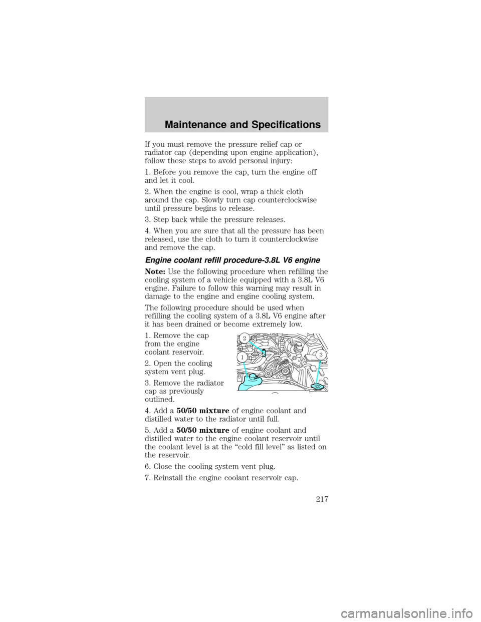
1. Remove the cap
from the engine
coolant reservoir.
2. Open the cooling
system vent plug.
3. Remove the radiator
cap as previously
outlined.
4. Add a50/50 mixtureof engine coolant and
distilled water to the radiator until full.
5. Add a50/50 mixtureof engine coolant and
distilled water to the engine coolant reservoir until
the coolant level is at the ªcold fill levelº as listed on
the reservoir.
6. Close the cooling system vent plug.
7. Reinstall the engine coolant reservoir cap.
2
31
Maintenance and Specifications
217