Page 6 of 104
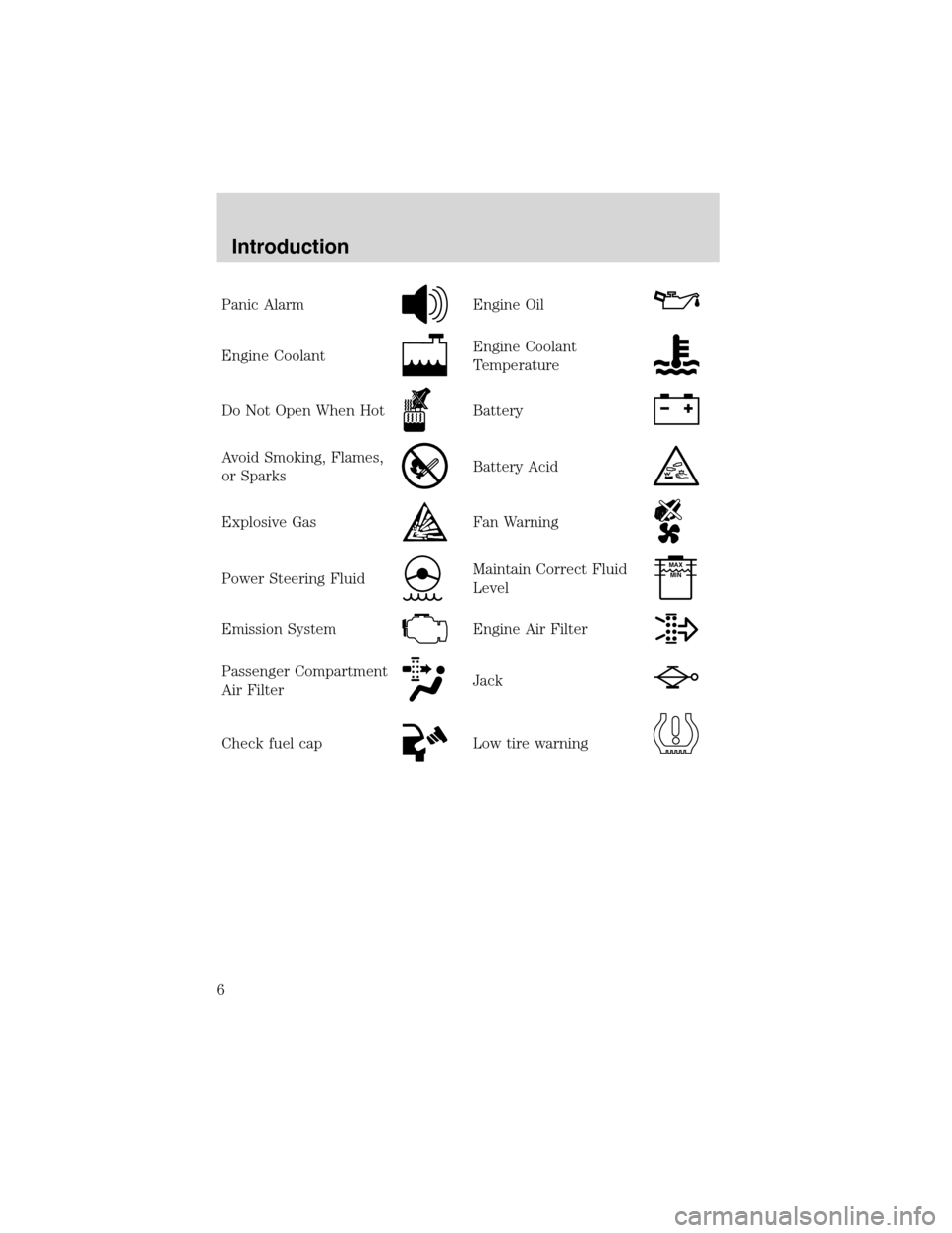
Panic AlarmEngine Oil
Engine CoolantEngine Coolant
Temperature
Do Not Open When HotBattery
Avoid Smoking, Flames,
or SparksBattery Acid
Explosive GasFan Warning
Power Steering FluidMaintain Correct Fluid
LevelMAX
MIN
Emission SystemEngine Air Filter
Passenger Compartment
Air FilterJack
Check fuel capLow tire warning
Introduction
6
Page 10 of 104
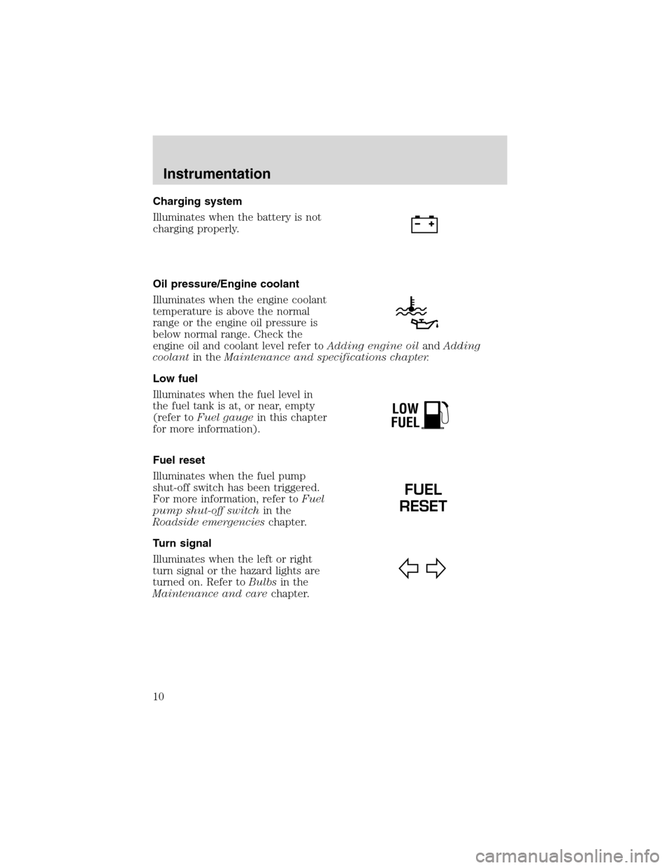
Charging system
Illuminates when the battery is not
charging properly.
Oil pressure/Engine coolant
Illuminates when the engine coolant
temperature is above the normal
range or the engine oil pressure is
below normal range. Check the
engine oil and coolant level refer toAdding engine oilandAdding
coolantin theMaintenance and specifications chapter.
Low fuel
Illuminates when the fuel level in
the fuel tank is at, or near, empty
(refer toFuel gaugein this chapter
for more information).
Fuel reset
Illuminates when the fuel pump
shut-off switch has been triggered.
For more information, refer toFuel
pump shut-off switchin the
Roadside emergencieschapter.
Turn signal
Illuminates when the left or right
turn signal or the hazard lights are
turned on. Refer toBulbsin the
Maintenance and carechapter.
LOW
FUEL
FUEL
RESET
Instrumentation
10
Page 12 of 104
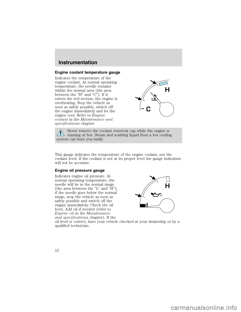
Engine coolant temperature gauge
Indicates the temperature of the
engine coolant. At normal operating
temperature, the needle remains
within the normal area (the area
between the “H” and “C”). If it
enters the red section, the engine is
overheating. Stop the vehicle as
soon as safely possible, switch off
the engine immediately and let the
engine cool. Refer toEngine
coolantin theMaintenance and
specificationschapter.
Never remove the coolant reservoir cap while the engine is
running or hot. Steam and scalding liquid from a hot cooling
system can burn you badly.
This gauge indicates the temperature of the engine coolant, not the
coolant level. If the coolant is not at its proper level the gauge indication
will not be accurate.
Engine oil pressure gauge
Indicates engine oil pressure. At
normal operating temperature, the
needle will be in the normal range
(the area between the “L” and “H”);
if the needle goes below the normal
range, stop the vehicle as soon as
safely possible and switch off the
engine immediately. Check the oil
level. Add oil if needed (refer to
Engine oilin theMaintenance
and specificationschapter). If the
oil level is correct, have your vehicle checked at your dealership or by a
qualified technician.
H
C
L
H
Instrumentation
12
Page 42 of 104
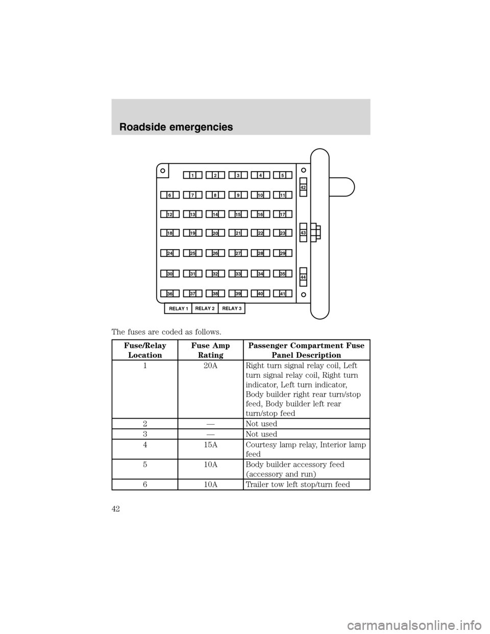
The fuses are coded as follows.
Fuse/Relay
LocationFuse Amp
RatingPassenger Compartment Fuse
Panel Description
1 20A Right turn signal relay coil, Left
turn signal relay coil, Right turn
indicator, Left turn indicator,
Body builder right rear turn/stop
feed, Body builder left rear
turn/stop feed
2 — Not used
3 — Not used
4 15A Courtesy lamp relay, Interior lamp
feed
5 10A Body builder accessory feed
(accessory and run)
6 10A Trailer tow left stop/turn feed
1234
5
7
689101142
43
44 13 12 14
15 16 17
19 18
2021 22 23
25 24
26 27 28 29
31 30 32 33 3435
37
3638 3940
41
RELAY 1RELAY 2 RELAY 3
Roadside emergencies
42
Page 43 of 104
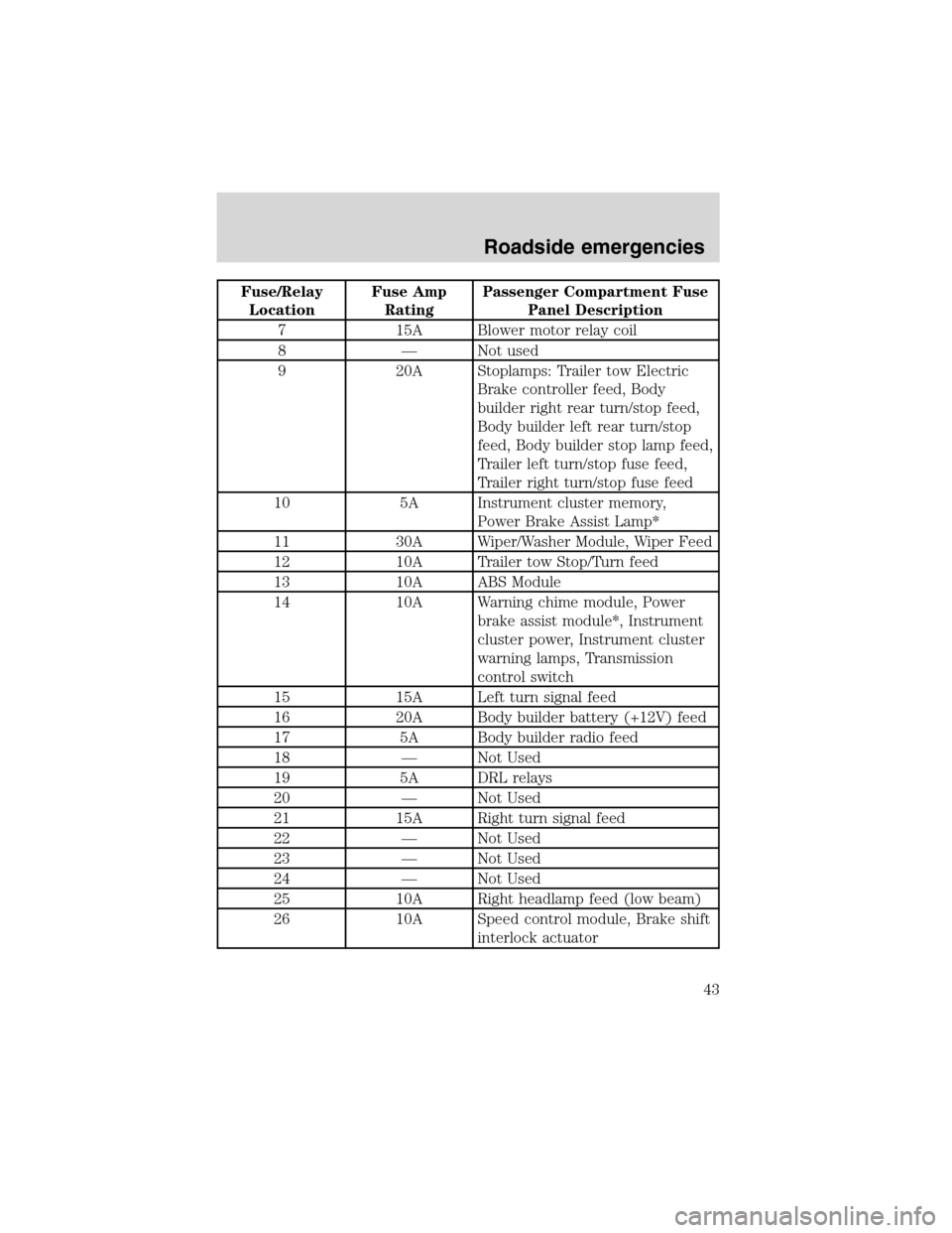
Fuse/Relay
LocationFuse Amp
RatingPassenger Compartment Fuse
Panel Description
7 15A Blower motor relay coil
8 — Not used
9 20A Stoplamps: Trailer tow Electric
Brake controller feed, Body
builder right rear turn/stop feed,
Body builder left rear turn/stop
feed, Body builder stop lamp feed,
Trailer left turn/stop fuse feed,
Trailer right turn/stop fuse feed
10 5A Instrument cluster memory,
Power Brake Assist Lamp*
11 30A Wiper/Washer Module, Wiper Feed
12 10A Trailer tow Stop/Turn feed
13 10A ABS Module
14 10A Warning chime module, Power
brake assist module*, Instrument
cluster power, Instrument cluster
warning lamps, Transmission
control switch
15 15A Left turn signal feed
16 20A Body builder battery (+12V) feed
17 5A Body builder radio feed
18 — Not Used
19 5A DRL relays
20 — Not Used
21 15A Right turn signal feed
22 — Not Used
23 — Not Used
24 — Not Used
25 10A Right headlamp feed (low beam)
26 10A Speed control module, Brake shift
interlock actuator
Roadside emergencies
43
Page 46 of 104
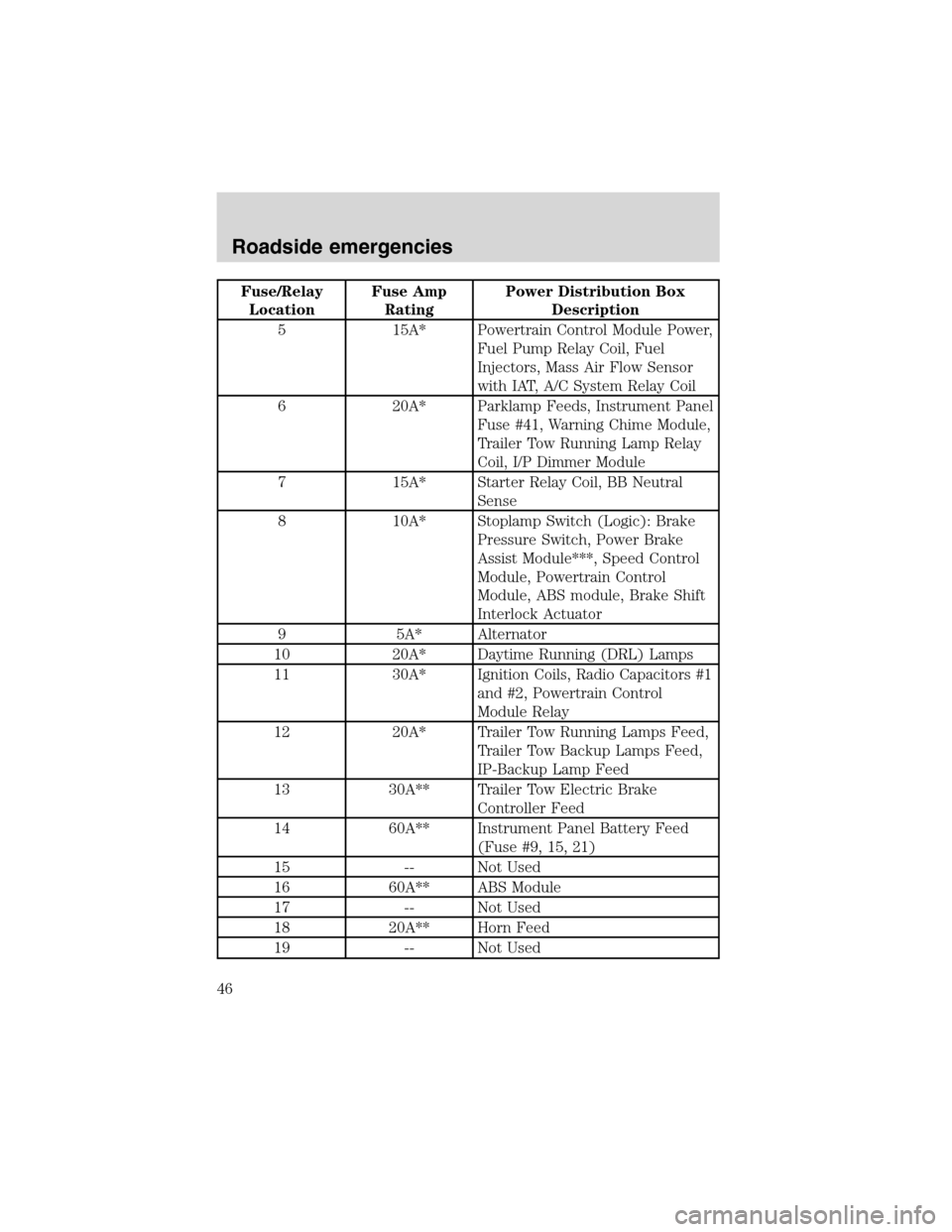
Fuse/Relay
LocationFuse Amp
RatingPower Distribution Box
Description
5 15A* Powertrain Control Module Power,
Fuel Pump Relay Coil, Fuel
Injectors, Mass Air Flow Sensor
with IAT, A/C System Relay Coil
6 20A* Parklamp Feeds, Instrument Panel
Fuse #41, Warning Chime Module,
Trailer Tow Running Lamp Relay
Coil, I/P Dimmer Module
7 15A* Starter Relay Coil, BB Neutral
Sense
8 10A* Stoplamp Switch (Logic): Brake
Pressure Switch, Power Brake
Assist Module***, Speed Control
Module, Powertrain Control
Module, ABS module, Brake Shift
Interlock Actuator
9 5A* Alternator
10 20A* Daytime Running (DRL) Lamps
11 30A* Ignition Coils, Radio Capacitors #1
and #2, Powertrain Control
Module Relay
12 20A* Trailer Tow Running Lamps Feed,
Trailer Tow Backup Lamps Feed,
IP-Backup Lamp Feed
13 30A** Trailer Tow Electric Brake
Controller Feed
14 60A** Instrument Panel Battery Feed
(Fuse #9, 15, 21)
15 -- Not Used
16 60A** ABS Module
17 -- Not Used
18 20A** Horn Feed
19 -- Not Used
Roadside emergencies
46
Page 51 of 104
Never use wheels or lug
nuts different than the
original equipment as this could
damage the wheel or mounting
system. This damage could allow
the wheels to come off while the
vehicle is being driven.
15. Replace any wheel trim.
16. Stow the jack, handle and lug wrench.
17. Unblock the wheels.
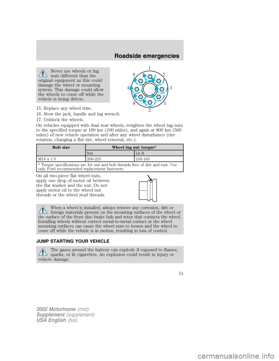
On vehicles equipped with dual rear wheels, retighten the wheel lug nuts
to the specified torque at 160 km (100 miles), and again at 800 km (500
miles) of new vehicle operation and after any wheel disturbance (tire
rotation, changing a flat tire, wheel removal, etc.).
Bolt size Wheel lug nut torque*
Nm Lb-ft
M14 x 1.5 200-225 150-165
* Torque specifications are for nut and bolt threads free of dirt and rust. Use
only Ford recommended replacement fasteners.
On all two-piece flat wheel nuts,
apply one drop of motor oil between
the flat washer and the nut. Do not
apply motor oil to the wheel nut
threads or the wheel stud threads.
When a wheel is installed, always remove any corrosion, dirt or
foreign materials present on the mounting surfaces of the wheel or
the surface of the front disc brake hub and rotor that contacts the wheel.
Installing wheels without correct metal-to-metal contact at the wheel
mounting surfaces can cause the wheel nuts to loosen and the wheel to
come off while the vehicle is in motion, resulting in loss of control.
JUMP STARTING YOUR VEHICLE
The gases around the battery can explode if exposed to flames,
sparks, or lit cigarettes. An explosion could result in injury or
vehicle damage.
1
3 4
27 6
5 8
2002 Motorhome(mot)
Supplement(supplement)
USA English(fus)
Roadside emergencies
51
Page 60 of 104
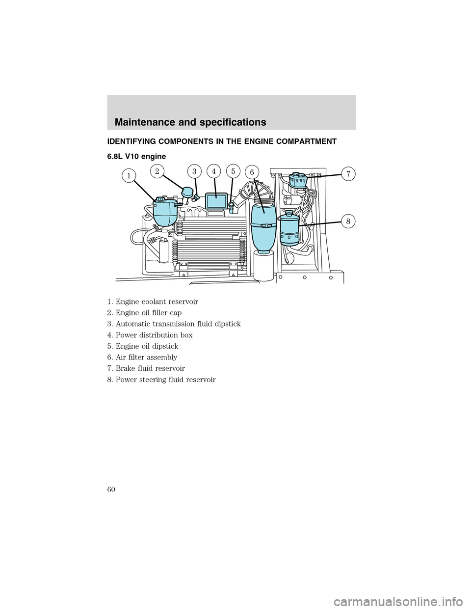
IDENTIFYING COMPONENTS IN THE ENGINE COMPARTMENT
6.8L V10 engine
1. Engine coolant reservoir
2. Engine oil filler cap
3. Automatic transmission fluid dipstick
4. Power distribution box
5. Engine oil dipstick
6. Air filter assembly
7. Brake fluid reservoir
8. Power steering fluid reservoir
Maintenance and specifications
60