Page 28 of 104
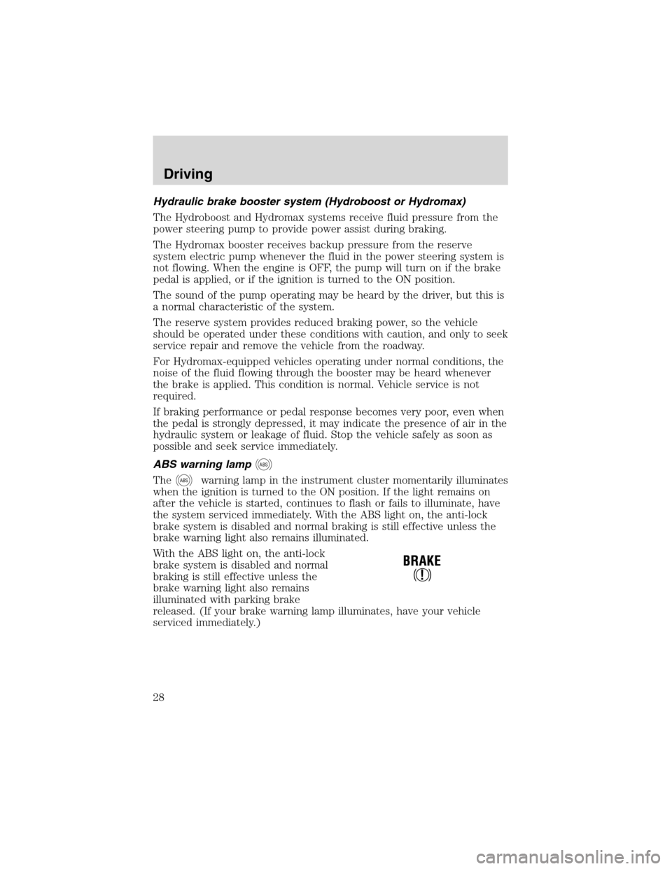
Hydraulic brake booster system (Hydroboost or Hydromax)
The Hydroboost and Hydromax systems receive fluid pressure from the
power steering pump to provide power assist during braking.
The Hydromax booster receives backup pressure from the reserve
system electric pump whenever the fluid in the power steering system is
not flowing. When the engine is OFF, the pump will turn on if the brake
pedal is applied, or if the ignition is turned to the ON position.
The sound of the pump operating may be heard by the driver, but this is
a normal characteristic of the system.
The reserve system provides reduced braking power, so the vehicle
should be operated under these conditions with caution, and only to seek
service repair and remove the vehicle from the roadway.
For Hydromax-equipped vehicles operating under normal conditions, the
noise of the fluid flowing through the booster may be heard whenever
the brake is applied. This condition is normal. Vehicle service is not
required.
If braking performance or pedal response becomes very poor, even when
the pedal is strongly depressed, it may indicate the presence of air in the
hydraulic system or leakage of fluid. Stop the vehicle safely as soon as
possible and seek service immediately.
ABS warning lamp
ABS
TheABSwarning lamp in the instrument cluster momentarily illuminates
when the ignition is turned to the ON position. If the light remains on
after the vehicle is started, continues to flash or fails to illuminate, have
the system serviced immediately. With the ABS light on, the anti-lock
brake system is disabled and normal braking is still effective unless the
brake warning light also remains illuminated.
With the ABS light on, the anti-lock
brake system is disabled and normal
braking is still effective unless the
brake warning light also remains
illuminated with parking brake
released. (If your brake warning lamp illuminates, have your vehicle
serviced immediately.)
Driving
28
Page 36 of 104
TRAILER TOWING
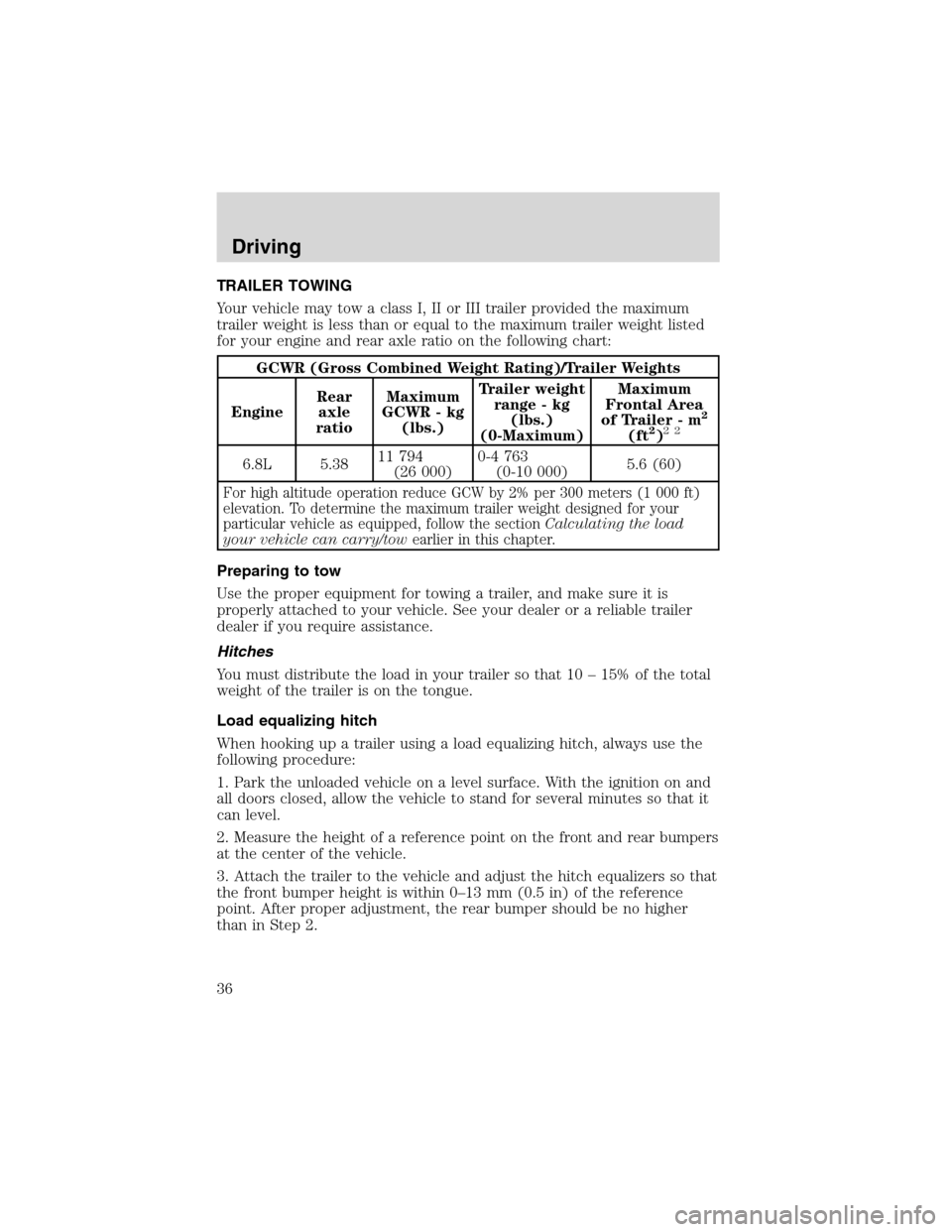
Your vehicle may tow a class I, II or III trailer provided the maximum
trailer weight is less than or equal to the maximum trailer weight listed
for your engine and rear axle ratio on the following chart:
GCWR (Gross Combined Weight Rating)/Trailer Weights
EngineRear
axle
ratioMaximum
GCWR - kg
(lbs.)Trailer weight
range - kg
(lbs.)
(0-Maximum)Maximum
Frontal Area
of Trailer - m
2
(ft2)22
6.8L 5.3811 794
(26 000)0-4 763
(0-10 000)5.6 (60)
For high altitude operation reduce GCW by 2% per 300 meters (1 000 ft)
elevation. To determine the maximum trailer weight designed for your
particular vehicle as equipped, follow the sectionCalculating the load
your vehicle can carry/towearlier in this chapter.
Preparing to tow
Use the proper equipment for towing a trailer, and make sure it is
properly attached to your vehicle. See your dealer or a reliable trailer
dealer if you require assistance.
Hitches
You must distribute the load in your trailer so that 10 – 15% of the total
weight of the trailer is on the tongue.
Load equalizing hitch
When hooking up a trailer using a load equalizing hitch, always use the
following procedure:
1. Park the unloaded vehicle on a level surface. With the ignition on and
all doors closed, allow the vehicle to stand for several minutes so that it
can level.
2. Measure the height of a reference point on the front and rear bumpers
at the center of the vehicle.
3. Attach the trailer to the vehicle and adjust the hitch equalizers so that
the front bumper height is within 0–13 mm (0.5 in) of the reference
point. After proper adjustment, the rear bumper should be no higher
than in Step 2.
Driving
36
Page 46 of 104
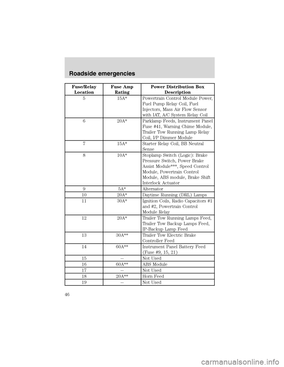
Fuse/Relay
LocationFuse Amp
RatingPower Distribution Box
Description
5 15A* Powertrain Control Module Power,
Fuel Pump Relay Coil, Fuel
Injectors, Mass Air Flow Sensor
with IAT, A/C System Relay Coil
6 20A* Parklamp Feeds, Instrument Panel
Fuse #41, Warning Chime Module,
Trailer Tow Running Lamp Relay
Coil, I/P Dimmer Module
7 15A* Starter Relay Coil, BB Neutral
Sense
8 10A* Stoplamp Switch (Logic): Brake
Pressure Switch, Power Brake
Assist Module***, Speed Control
Module, Powertrain Control
Module, ABS module, Brake Shift
Interlock Actuator
9 5A* Alternator
10 20A* Daytime Running (DRL) Lamps
11 30A* Ignition Coils, Radio Capacitors #1
and #2, Powertrain Control
Module Relay
12 20A* Trailer Tow Running Lamps Feed,
Trailer Tow Backup Lamps Feed,
IP-Backup Lamp Feed
13 30A** Trailer Tow Electric Brake
Controller Feed
14 60A** Instrument Panel Battery Feed
(Fuse #9, 15, 21)
15 -- Not Used
16 60A** ABS Module
17 -- Not Used
18 20A** Horn Feed
19 -- Not Used
Roadside emergencies
46
Page 47 of 104
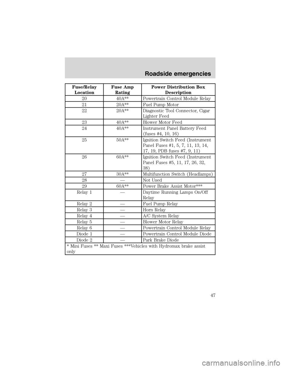
Fuse/Relay
LocationFuse Amp
RatingPower Distribution Box
Description
20 40A** Powertrain Control Module Relay
21 20A** Fuel Pump Motor
22 20A** Diagnostic Tool Connector, Cigar
Lighter Feed
23 40A** Blower Motor Feed
24 40A** Instrument Panel Battery Feed
(fuses #4, 10, 16)
25 50A** Ignition Switch Feed (Instrument
Panel Fuses #1, 5, 7, 11, 13, 14,
17, 19, PDB fuses #7, 9, 11)
26 60A** Ignition Switch Feed (Instrument
Panel Fuses #5, 11, 17, 26, 32,
38)
27 30A** Multifunction Switch (Headlamps)
28 — Not Used
29 60A** Power Brake Assist Motor***
Relay 1 — Daytime Running Lamps On/Off
Relay
Relay 2 — Fuel Pump Relay
Relay 3 — Horn Relay
Relay 4 — A/C System Relay
Relay 5 — Blower Motor Relay
Relay 6 — Powertrain Control Module Relay
Diode 1 — Powertrain Control Module Diode
Diode 2 — Park Brake Diode
* Mini Fuses ** Maxi Fuses ***Vehicles with Hydromax brake assist
only
Roadside emergencies
47