2002 DODGE RAM steering torque
[x] Cancel search: steering torquePage 32 of 2255
FRONT - 2WD
TABLE OF CONTENTS
page page
FRONT - 2WD
DESCRIPTION
DESCRIPTION........................7
DESCRIPTION........................8
SPECIFICATIONS
TORQUE CHART......................8
SPECIAL TOOLS
INDEPENDENT FRONT SUSPENSION......9
HUB / BEARING
REMOVAL.............................9
INSTALLATION..........................9
KNUCKLE
REMOVAL.............................10
INSTALLATION.........................10
LOWER BALL JOINT
DIAGNOSIS AND TESTING - LOWER BALL
JOINT..............................10
LOWER CONTROL ARM
REMOVAL.............................10INSTALLATION.........................10
SHOCK
DIAGNOSIS AND TESTING - SHOCK........11
REMOVAL.............................11
INSTALLATION.........................11
SPRING
REMOVAL.............................11
INSTALLATION.........................12
STABILIZER BAR
REMOVAL.............................12
INSTALLATION.........................12
UPPER BALL JOINT
DIAGNOSIS AND TESTING - UPPER BALL
JOINT..............................12
UPPER CONTROL ARM
REMOVAL.............................13
INSTALLATION.........................13
FRONT - 2WD
DESCRIPTION
DESCRIPTION
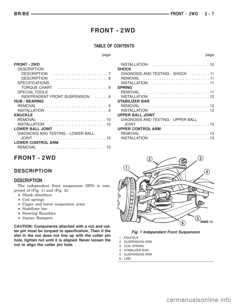
The independent front suspension (IFS) is com-
prised of (Fig. 1) and (Fig. 2):
²Shock absorbers
²Coil springs
²Upper and lower suspension arms
²Stabilizer bar
²Steering Knuckles
²Jounce Bumpers
CAUTION: Components attached with a nut and cot-
ter pin must be torqued to specification. Then if the
slot in the nut does not line up with the cotter pin
hole, tighten nut until it is aligned. Never loosen the
nut to align the cotter pin hole.
Fig. 1 Independent Front Suspension
1 - KNUCKLE
2 - SUSPENSION ARM
3 - COIL SPRING
4 - STABILIZER BAR
5 - SUSPENSION ARM
6 - LINK
BR/BEFRONT - 2WD 2 - 7
Page 39 of 2255
FRONT - 4WD
TABLE OF CONTENTS
page page
FRONT - 4WD
DESCRIPTION
DESCRIPTION........................14
DESCRIPTION........................15
SPECIFICATIONS
TORQUE CHART......................15
SPECIAL TOOLS
LINK/COIL SUSPENSION...............16
HUB / BEARING
REMOVAL.............................16
INSTALLATION.........................17
KNUCKLE
REMOVAL.............................19
INSTALLATION.........................19
UPPER CONTROL ARM
REMOVAL.............................19
INSTALLATION.........................19
UPPER BALL JOINT
REMOVAL - DANA 44 & 60................19
INSTALLATION
INSTALLATION - DANA 44 AXLE..........20
INSTALLATION - DANA 60 AXLE..........20
LOWER CONTROL ARM
REMOVAL.............................20INSTALLATION.........................20
LOWER BALL JOINT
REMOVAL
REMOVAL - DANA 44 AXLE..............21
REMOVAL - DANA 60 AXLE..............21
INSTALLATION
INSTALLATION - DANA 44 AXLE..........21
INSTALLATION - DANA 60 AXLE..........22
SHOCK
DIAGNOSIS AND TESTING - SHOCK........22
REMOVAL.............................22
INSTALLATION.........................22
SPRING
REMOVAL.............................23
INSTALLATION.........................23
STABILIZER BAR
REMOVAL.............................23
INSTALLATION.........................23
TRACK BAR
DIAGNOSIS AND TESTING - TRACK BAR....24
REMOVAL.............................24
INSTALLATION.........................24
FRONT - 4WD
DESCRIPTION
DESCRIPTION
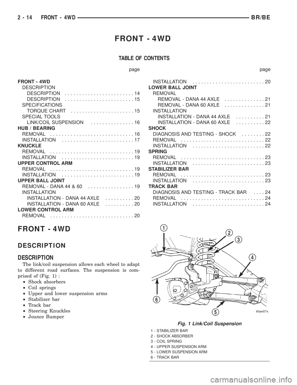
The link/coil suspension allows each wheel to adapt
to different road surfaces. The suspension is com-
prised of (Fig. 1) :
²Shock absorbers
²Coil springs
²Upper and lower suspension arms
²Stabilizer bar
²Track bar
²Steering Knuckles
²Jounce Bumper
Fig. 1 Link/Coil Suspension
1 - STABILIZER BAR
2 - SHOCK ABSORBER
3 - COIL SPRING
4 - UPPER SUSPENSION ARM
5 - LOWER SUSPENSION ARM
6 - TRACK BAR
2 - 14 FRONT - 4WDBR/BE
Page 44 of 2255

KNUCKLE
REMOVAL
(1) Remove hub bearing and axle shaft.
(2) Remove tie-rod or drag link end from the steer-
ing knuckle arm.
(3) Remove the ABS sensor wire and bracket from
knuckle. Refer to Brakes, for proper procedures.
(4) Remove the cotter pin from the upper ball stud
nut. Remove the upper and lower ball stud nuts.
(5) Strike the steering knuckle with a brass ham-
mer to loosen.
(6) Remove knuckle from axle tube yokes.
INSTALLATION
(1) Position the steering knuckle on the ball studs.
(2) Install and tighten lower ball stud nut to 47
N´m (35 ft. lbs.) torque. Do not install cotter pin at
this time.
(3) Install and tighten upper ball stud nut to 94
N´m (70 ft. lbs.) torque. Advance nut to next slot to
line up hole and install new cotter pin.
(4) Retorque lower ball stud nut to 190±217 N´m
(140±160 ft. lbs.) torque. Advance nut to next slot to
line up hole and install new cotter pin.
(5) Install the hub bearing and axle shaft.
(6) Install tie-rod or drag link end onto the steer-
ing knuckle arm.
(7) Install the ABS sensor wire and bracket to the
knuckle. Refer to Brakes, for proper procedure.
UPPER CONTROL ARM
REMOVAL
(1) Raise and support the vehicle.
(2) Remove the upper suspension arm nut and bolt
at the axle bracket (Fig. 12).
(3) Remove the nut and bolt at the frame rail and
remove the upper suspension arm.
INSTALLATION
(1) Position the upper suspension arm at the axle
and frame rail.
(2) Install the bolts and finger tighten the nuts.
(3) Remove the supports and lower the vehicle.
(4) Tighten nut at the axle bracket to 163 N´m
(120 ft. lbs.). Tighten nut at frame bracket to 163
N´m (120 ft. lbs.).
UPPER BALL JOINT
REMOVAL - DANA 44 & 60
(1) Position tools as shown to remove upper ball
stud (Fig. 13).
Fig. 12 Upper and Lower Suspension Arm
1 - STABILIZER BAR
2 - SHOCK ABSORBER
3 - COIL SPRING
4 - UPPER SUSPENSION ARM
5 - LOWER SUSPENSION ARM
6 - TRACK BAR
Fig. 13 UPPER BALL JOINT REMOVAL
1 - SPECIAL TOOL C4212-F
2 - SPECIAL TOOL 6761
3 - KNUCKLE
4 - SPECIAL TOOL 8445-3
BR/BEFRONT - 4WD 2 - 19
Page 50 of 2255
REAR
TABLE OF CONTENTS
page page
REAR
DESCRIPTION.........................25
DIAGNOSIS AND TESTING - SPRING AND
SHOCK.............................25
SPECIFICATIONS
TORQUE CHART......................26
SPECIAL TOOLS
SUSPENSION-REAR...................27
BUSHINGS
REMOVAL.............................27INSTALLATION.........................27
SHOCK
REMOVAL.............................27
INSTALLATION.........................27
SPRING
REMOVAL.............................27
INSTALLATION.........................28
STABILIZER BAR
REMOVAL.............................29
INSTALLATION.........................29
REAR
DESCRIPTION
The rear suspension is comprised of:
²Shock Absorbers
²Jounce Bumpers
²Stabilizer Bar (optional)
²Leaf Springs
²Drive Axle
CAUTION: A vehicle should always be loaded so
the vehicle weight center-line is located immedi-
ately forward of the rear axle. Correct vehicle load-
ing provides proper front tire-to-road contact. This
results in maximum vehicle handling stability and
safety. Incorrect vehicle weight distribution can
cause excessive tire tread wear, spring fatigue or
failure, and erratic steering.
CAUTION: Suspension components with rubber/ure-
thane bushings (except stabilizer bar) should be
tightened with the vehicle at normal ride height. It is
important to have the springs supporting the weight
of the vehicle when the fasteners are torqued. If
springs are not at their normal ride position, vehicle
ride comfort could be affected and premature bush-
ing wear may occur.
DIAGNOSIS AND TESTING - SPRING AND
SHOCK
A knocking or rattling noise from a shock absorber
may be caused by movement between mounting
bushings and metal brackets or attaching compo-
nents. These noises can usually be stopped by tight-
ening the attaching nuts. If the noise persists,
inspect for damaged and worn bushings, and attach-
ing components. Repair as necessary if any of these
conditions exist.
A squeaking noise from the shock absorber may be
caused by the hydraulic valving and may be intermit-
tent. This condition is not repairable and the shock
absorber must be replaced.
The shock absorbers are not refillable or adjust-
able. If a malfunction occurs, the shock absorber
must be replaced. To test a shock absorber, hold it in
an upright position and force the piston in and out of
the cylinder four or five times. The action throughout
each stroke should be smooth and even.
The spring eye and shock absorber bushings do not
require any type of lubrication. Do not attempt to
stop spring bushing noise by lubricating them.
Grease and mineral oil-base lubricants will deterio-
rate the bushing rubber.
If the vehicle is used for severe, off-road operation,
the springs should be examined periodically. Check
for broken and shifted leafs, loose and missing clips,
and broken center bolts. Refer to Spring and Shock
Absorber Diagnosis chart for additional information.
BR/BEREAR 2 - 25
Page 73 of 2255

Condition Possible Causes Correction
Gear Teeth Broke 1. Overloading. 1. Replace gears. Examine other
gears and bearings for possible
damage.
2. Erratic clutch operation. 2. Replace gears and examine the
remaining parts for damage. Avoid
erratic clutch operation.
3. Ice-spotted pavement. 3. Replace gears and examine
remaining parts for damage.
4. Improper adjustments. 4. Replace gears and examine
remaining parts for damage. Ensure
ring gear backlash is correct.
Axle Noise 1. Insufficient lubricant. 1. Fill differential with the correct
fluid type and quantity.
2. Improper ring gear and pinion
adjustment.2. Check ring gear and pinion
contact pattern.
3. Unmatched ring gear and pinion. 3. Replace gears with a matched
ring gear and pinion.
4. Worn teeth on ring gear and/or
pinion.4. Replace ring gear and pinion.
5. Loose pinion bearings. 5. Adjust pinion bearing pre-load.
6. Loose differential bearings. 6. Adjust differential bearing
pre-load.
7. Mis-aligned or sprung ring gear. 7. Measure ring gear run-out.
Replace components as necessary.
8. Loose differential bearing cap
bolts.8. Inspect differential components
and replace as necessary. Ensure
that the bearing caps are torqued
tot he proper specification.
9. Housing not machined properly. 9. Replace housing.
REMOVAL
(1) Raise and support the vehicle.
(2) Remove wheels and tires.
(3) Remove brake calipers and rotors. Refer to 5
Brakes for procedures.
(4) Remove ABS wheel speed sensors, if equipped.
Refer to 5 Brakes for procedures.
(5) Disconnect axle vent hose.
(6) Disconnect vacuum hose and electrical connec-
tor at disconnect housing.
(7) Remove front propeller shaft.
(8) Disconnect stabilizer bar links at the axle
brackets.
(9) Disconnect shock absorbers from axle brackets.
(10) Disconnect track bar from the axle bracket.
(11) Disconnect tie rod and drag link from the
steering knuckles.
(12) Position suitable lifting device under the axle
assembly.(13) Secure axle to lifting device.
(14) Mark suspension alignment cams for installa-
tion reference.
(15) Disconnect upper and lower suspension arms
from the axle bracket.
(16) Lower the axle. The coil springs will drop
with the axle.
(17) Remove the coil springs from the axle bracket.
INSTALLATION
CAUTION: Suspension components with rubber
bushings should be tightened with the weight of the
vehicle on the suspension, at normal height. If
springs are not at their normal ride position, vehicle
ride comfort could be affected and premature bush-
ing wear may occur. Rubber bushings must never
be lubricated.
(1) Support the axle on a suitable lifting device.
3 - 18 FRONT AXLE - 248FBIBR/BE
FRONT AXLE - 248FBI (Continued)
Page 224 of 2255
BRAKES - ABS
TABLE OF CONTENTS
page page
BRAKES - ABS
DESCRIPTION.........................35
OPERATION...........................36
DIAGNOSIS AND TESTING - ANTILOCK
BRAKES............................36
STANDARD PROCEDURE
STANDARD PROCEDURE - RWAL SERVICE
PRECAUTIONS.......................36
STANDARD PROCEDURE - BLEEDING ABS
BRAKE SYSTEM......................36
SPECIFICATIONS
TORQUE CHART......................37
FRONT WHEEL SPEED SENSOR
DESCRIPTION.........................38
OPERATION...........................38
REMOVAL
REMOVAL - 4X2......................39REMOVAL - 4X4......................39
INSTALLATION
INSTALLATION - 4X2...................39
INSTALLATION - 4X4...................39
REAR WHEEL SPEED SENSOR
DIAGNOSIS AND TESTING - REAR WHEEL
SPEED SENSOR......................40
REMOVAL.............................40
INSTALLATION.........................40
HCU (HYDRAULIC CONTROL UNIT)
DESCRIPTION.........................40
OPERATION...........................40
REMOVAL.............................41
INSTALLATION.........................41
BRAKES - ABS
DESCRIPTION
The antilock brake system (ABS) is an electroni-
cally operated, all wheel brake control system. 2500
and 3500 vehicles have Electronic Brake Distribution
(EBD) designed into the systen which eliminates the
combination/proportioning valve.
The system is designed to prevent wheel lockup
and maintain steering control during periods of high
wheel slip when braking. Preventing lockup is accom-
plished by modulating fluid pressure to the wheel
brake units.
The hydraulic system is a three channel design.
The front wheel brakes are controlled individually
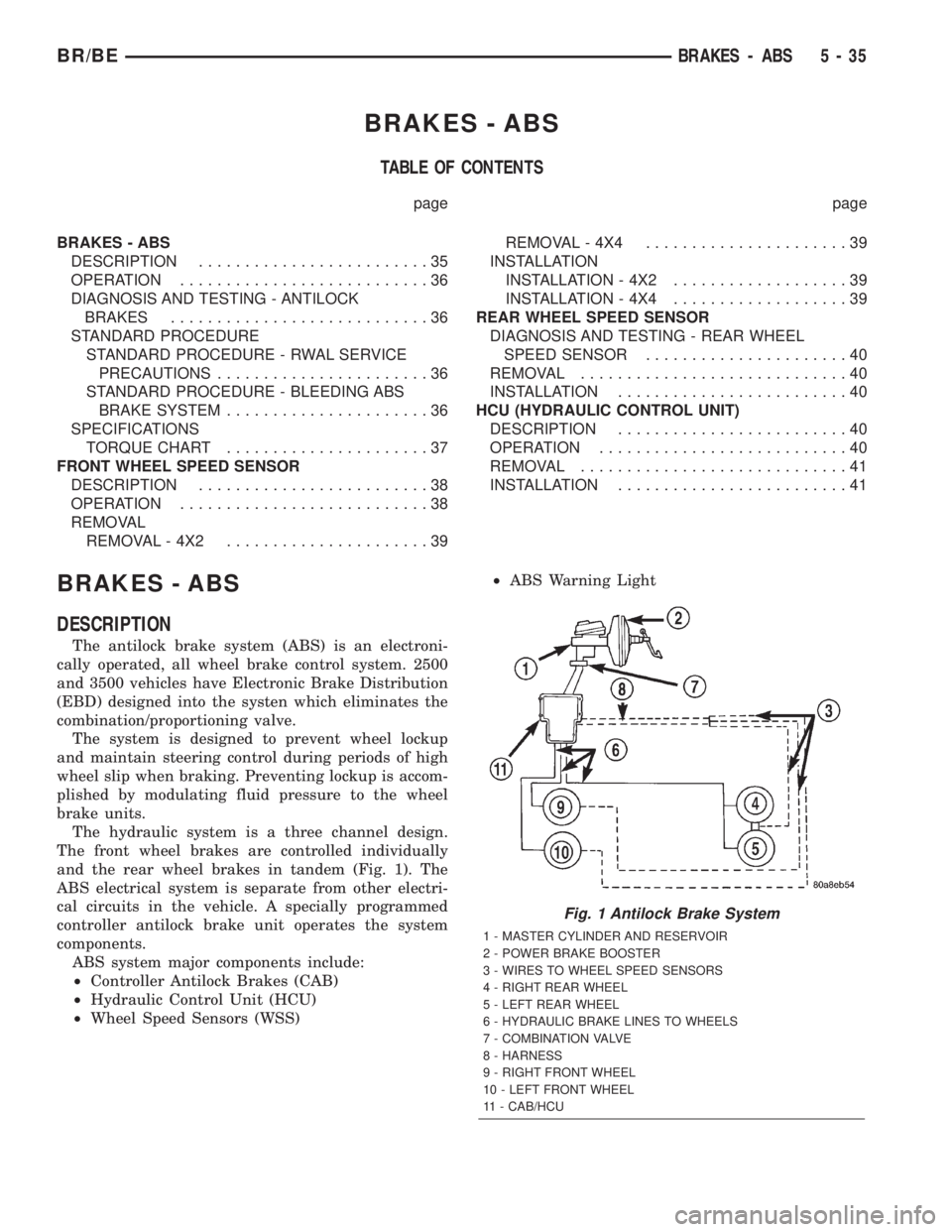
and the rear wheel brakes in tandem (Fig. 1). The
ABS electrical system is separate from other electri-
cal circuits in the vehicle. A specially programmed
controller antilock brake unit operates the system
components.
ABS system major components include:
²Controller Antilock Brakes (CAB)
²Hydraulic Control Unit (HCU)
²Wheel Speed Sensors (WSS)²ABS Warning Light
Fig. 1 Antilock Brake System
1 - MASTER CYLINDER AND RESERVOIR
2 - POWER BRAKE BOOSTER
3 - WIRES TO WHEEL SPEED SENSORS
4 - RIGHT REAR WHEEL
5 - LEFT REAR WHEEL
6 - HYDRAULIC BRAKE LINES TO WHEELS
7 - COMBINATION VALVE
8 - HARNESS
9 - RIGHT FRONT WHEEL
10 - LEFT FRONT WHEEL
11 - CAB/HCU
BR/BEBRAKES - ABS 5 - 35
Page 269 of 2255
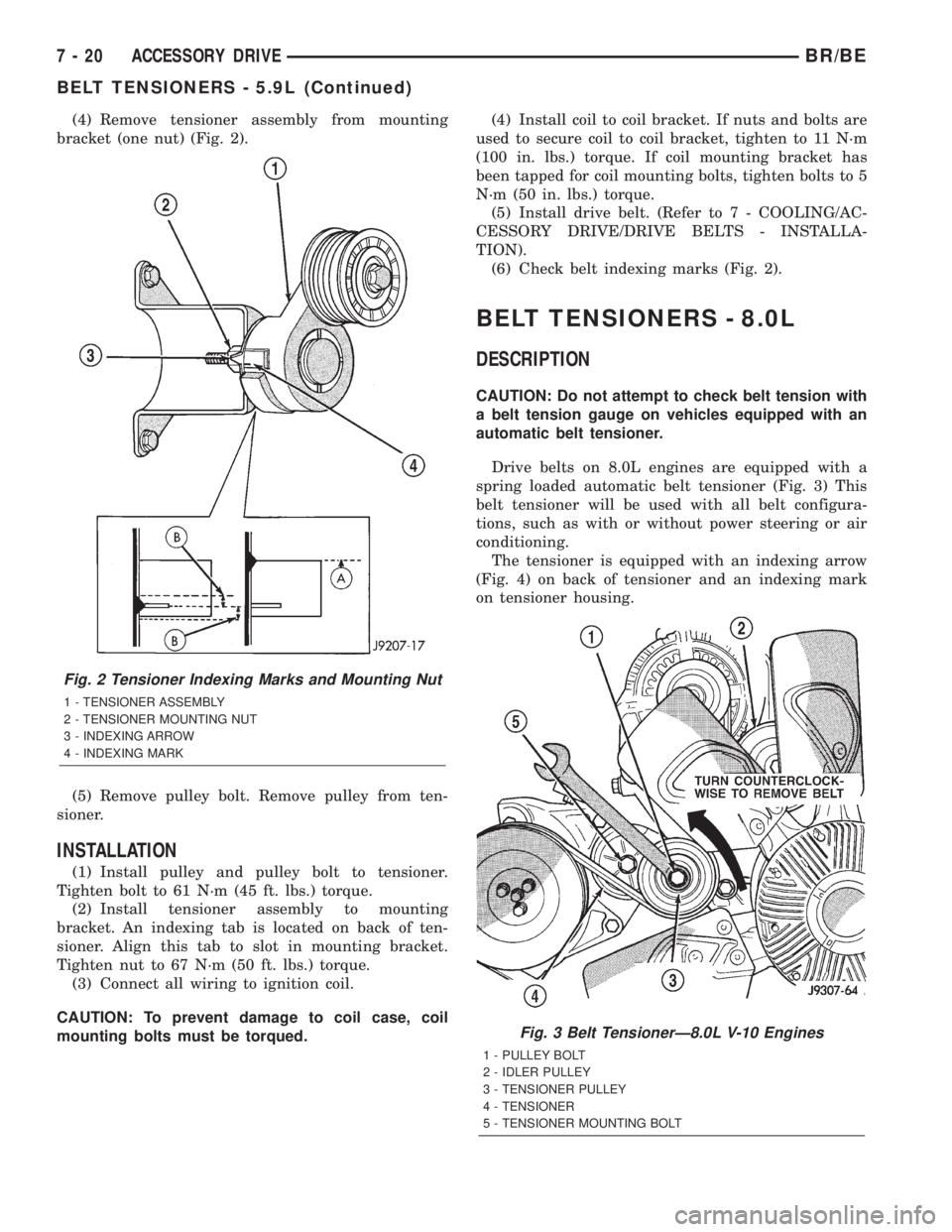
(4) Remove tensioner assembly from mounting
bracket (one nut) (Fig. 2).
(5) Remove pulley bolt. Remove pulley from ten-
sioner.
INSTALLATION
(1) Install pulley and pulley bolt to tensioner.
Tighten bolt to 61 N´m (45 ft. lbs.) torque.
(2) Install tensioner assembly to mounting
bracket. An indexing tab is located on back of ten-
sioner. Align this tab to slot in mounting bracket.
Tighten nut to 67 N´m (50 ft. lbs.) torque.
(3) Connect all wiring to ignition coil.
CAUTION: To prevent damage to coil case, coil
mounting bolts must be torqued.(4) Install coil to coil bracket. If nuts and bolts are
used to secure coil to coil bracket, tighten to 11 N´m
(100 in. lbs.) torque. If coil mounting bracket has
been tapped for coil mounting bolts, tighten bolts to 5
N´m (50 in. lbs.) torque.
(5) Install drive belt. (Refer to 7 - COOLING/AC-
CESSORY DRIVE/DRIVE BELTS - INSTALLA-
TION).
(6) Check belt indexing marks (Fig. 2).
BELT TENSIONERS - 8.0L
DESCRIPTION
CAUTION: Do not attempt to check belt tension with
a belt tension gauge on vehicles equipped with an
automatic belt tensioner.
Drive belts on 8.0L engines are equipped with a
spring loaded automatic belt tensioner (Fig. 3) This
belt tensioner will be used with all belt configura-
tions, such as with or without power steering or air
conditioning.
The tensioner is equipped with an indexing arrow
(Fig. 4) on back of tensioner and an indexing mark
on tensioner housing.
Fig. 2 Tensioner Indexing Marks and Mounting Nut
1 - TENSIONER ASSEMBLY
2 - TENSIONER MOUNTING NUT
3 - INDEXING ARROW
4 - INDEXING MARK
Fig. 3 Belt TensionerÐ8.0L V-10 Engines
1 - PULLEY BOLT
2 - IDLER PULLEY
3 - TENSIONER PULLEY
4 - TENSIONER
5 - TENSIONER MOUNTING BOLT
7 - 20 ACCESSORY DRIVEBR/BE
BELT TENSIONERS - 5.9L (Continued)
Page 272 of 2255
BELT TENSIONERS - 5.9L
DIESEL
DESCRIPTION
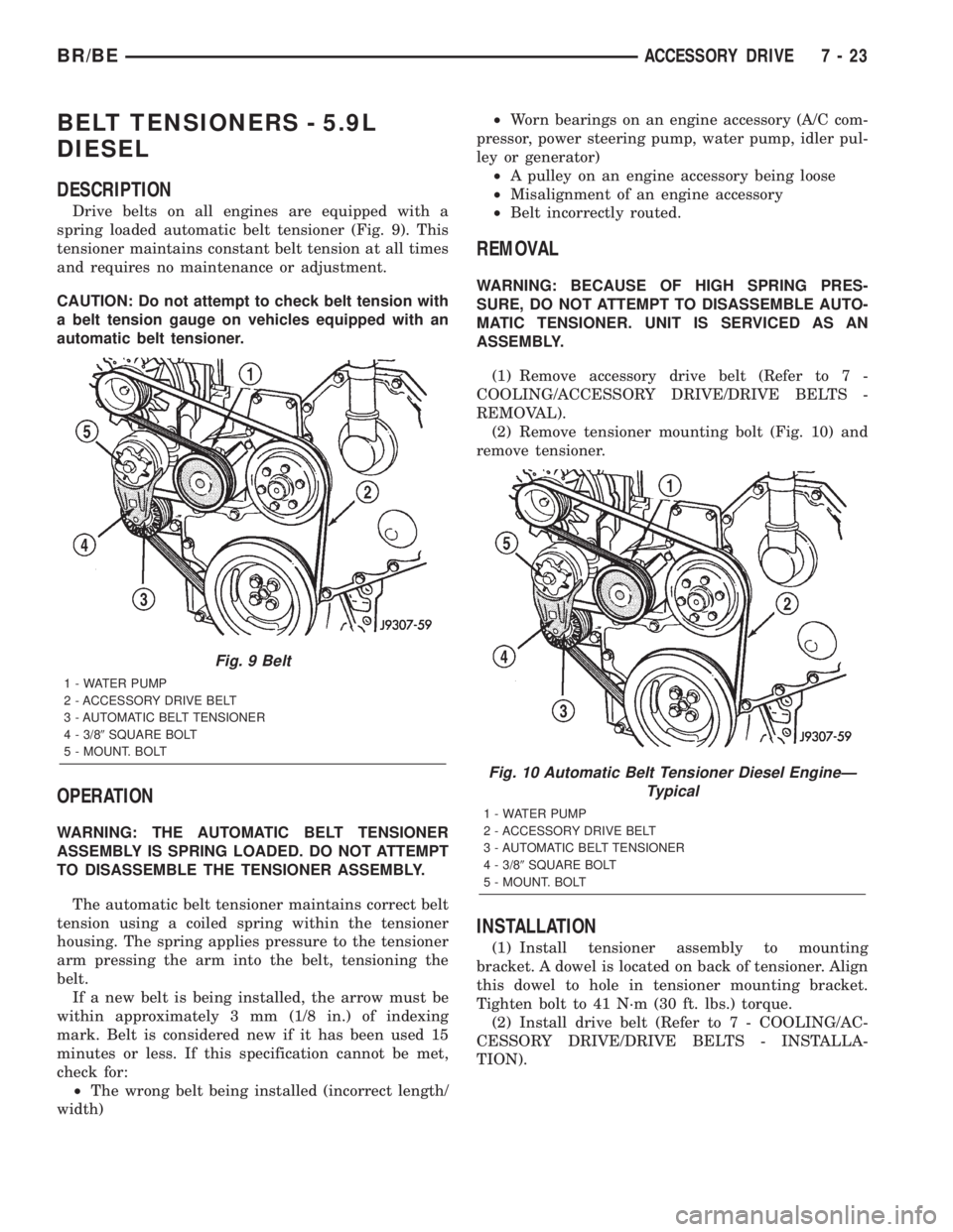
Drive belts on all engines are equipped with a
spring loaded automatic belt tensioner (Fig. 9). This
tensioner maintains constant belt tension at all times
and requires no maintenance or adjustment.
CAUTION: Do not attempt to check belt tension with
a belt tension gauge on vehicles equipped with an
automatic belt tensioner.
OPERATION
WARNING: THE AUTOMATIC BELT TENSIONER
ASSEMBLY IS SPRING LOADED. DO NOT ATTEMPT
TO DISASSEMBLE THE TENSIONER ASSEMBLY.
The automatic belt tensioner maintains correct belt
tension using a coiled spring within the tensioner
housing. The spring applies pressure to the tensioner
arm pressing the arm into the belt, tensioning the
belt.
If a new belt is being installed, the arrow must be
within approximately 3 mm (1/8 in.) of indexing
mark. Belt is considered new if it has been used 15
minutes or less. If this specification cannot be met,
check for:
²The wrong belt being installed (incorrect length/
width)²Worn bearings on an engine accessory (A/C com-
pressor, power steering pump, water pump, idler pul-
ley or generator)
²A pulley on an engine accessory being loose
²Misalignment of an engine accessory
²Belt incorrectly routed.
REMOVAL
WARNING: BECAUSE OF HIGH SPRING PRES-
SURE, DO NOT ATTEMPT TO DISASSEMBLE AUTO-
MATIC TENSIONER. UNIT IS SERVICED AS AN
ASSEMBLY.
(1) Remove accessory drive belt (Refer to 7 -
COOLING/ACCESSORY DRIVE/DRIVE BELTS -
REMOVAL).
(2) Remove tensioner mounting bolt (Fig. 10) and
remove tensioner.
INSTALLATION
(1) Install tensioner assembly to mounting
bracket. A dowel is located on back of tensioner. Align
this dowel to hole in tensioner mounting bracket.
Tighten bolt to 41 N´m (30 ft. lbs.) torque.
(2) Install drive belt (Refer to 7 - COOLING/AC-
CESSORY DRIVE/DRIVE BELTS - INSTALLA-
TION).
Fig. 9 Belt
1 - WATER PUMP
2 - ACCESSORY DRIVE BELT
3 - AUTOMATIC BELT TENSIONER
4 - 3/89SQUARE BOLT
5 - MOUNT. BOLT
Fig. 10 Automatic Belt Tensioner Diesel EngineÐ
Typical
1 - WATER PUMP
2 - ACCESSORY DRIVE BELT
3 - AUTOMATIC BELT TENSIONER
4 - 3/89SQUARE BOLT
5 - MOUNT. BOLT
BR/BEACCESSORY DRIVE 7 - 23