2002 DODGE RAM oil filter
[x] Cancel search: oil filterPage 1249 of 2255
INSTALLATION
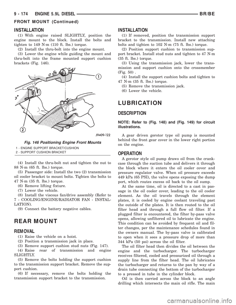
(1) With engine raised SLIGHTLY, position the
engine mount to the block. Install the bolts and
tighten to 149 N´m (110 ft. lbs.) torque.
(2) Install the thru-bolt into the engine mount.
(3) Lower the engine while guiding the mount and
thru-bolt into the frame mounted support cushion
brackets (Fig. 146).
(4) Install the thru-bolt nut and tighten the nut to
88 N´m (65 ft. lbs.) torque.
(5) Passenger side: Install the two (2) transmission
oil cooler bracket to mount bolts. Tighten the bolts to
47 N´m (35 ft. lbs.) torque.
(6) Remove lifting fixture.
(7) Lower the vehicle.
(8) Install the viscous fan/drive assembly (Refer to
7 - COOLING/ENGINE/RADIATOR FAN - INSTAL-
LATION).
(9) Connect the battery negative cables.
REAR MOUNT
REMOVAL
(1) Raise the vehicle on a hoist.
(2) Position a transmission jack in place.
(3) Remove support cushion stud nuts (Fig. 147).
(4) Raise rear of transmission and engine
SLIGHTLY.
(5) Remove the bolts holding the support cushion
to the transmission support bracket. Remove the sup-
port cushion.
(6) If necessary, remove the bolts holding the
transmission support bracket to the transmission.
INSTALLATION
(1) If removed, position the transmission support
bracket to the transmission. Install new attaching
bolts and tighten to 102 N´m (75 ft. lbs.) torque.
(2) Position support cushion to transmission sup-
port bracket. Install stud nuts and tighten to 47 N´m
(35 ft. lbs.) torque.
(3) Using the transmission jack, lower the trans-
mission and support cushion onto the crossmember
(Fig. 50) .
(4) Install the support cushion bolts and tighten to
47 N´m (35 ft. lbs.) torque.
(5) Remove the transmission jack.
(6) Lower the vehicle.
LUBRICATION
DESCRIPTION
NOTE: Refer to (Fig. 148) and (Fig. 149) for circuit
illustrations.
A gear driven gerotor type oil pump is mounted
behind the front gear cover in the lower right portion
on the engine.
OPERATION
A gerotor style oil pump draws oil from the crank-
case through the suction tube and delivers it through
the block where it enters the oil cooler cover and
pressure regulator valve. When oil pressure exceeds
449 kPa (65 PSI), the valve opens exposing the dump
port, which routes excess oil back to the oil sump.
At the same time, oil is directed to a cast in pas-
sage in the oil cooler cover, leading to the oil cooler
element. As the oil travels through the element
plates, it is cooled by engine coolant traveling past
the outside of the plates. It is then routed to the oil
filter head and through a full flow oil filter. If a
plugged filter is encountered, the filter by-pass valve
opens, allowing unfiltered oil to lubricate the engine.
This condition can be avoided by frequent oil and fil-
ter changes, per the maintenance schedules found in
the owners manual. The by-pass valve is calibrated
to open when it sees a pressure drop of more than
344 kPa (50 psi) across the oil filter.
The oil filter head then divides the oil between the
engine and the turbocharger. The turbocharger
receives filtered, cooled and pressurized oil through a
supply line from the filter head. The oil lubricates
the turbocharger and returns to the pan by way of a
drain tube connecting the bottom of the turbocharger
to a pressed in tube in the cylinder block.
Oil is then carried across the block to an angle
drilling which intersects the main oil rifle. The main
Fig. 146 Positioning Engine Front Mounts
1 - ENGINE SUPPORT BRACKET/CUSHION
2 - SUPPORT CUSHION BRACKET
9 - 174 ENGINE 5.9L DIESELBR/BE
FRONT MOUNT (Continued)
Page 1251 of 2255

Fig. 148 Lubrication System Circulation
1 - TO FILTER
2 - FROM FILTER
3 - TO MAIN OIL RIFLE
4 - CLOSED
5 - OPEN
6 - TO COOLER
7 - FROM PUMP8 - CLOSED
9 - OPEN
10 - TO OIL SUMP
11 - OIL DRAIN
12 - OIL SUPPLY
9 - 176 ENGINE 5.9L DIESELBR/BE
LUBRICATION (Continued)
Page 1253 of 2255

DIAGNOSIS AND TESTINGÐENGINE OIL
PRESSURE
(1) Remove the engine oil pressure sensor and
install Oil Pressure Line and Gauge Tool C-3292 with
a suitable adapter.
(2) Start engine and warm to operating tempera-
ture.
(3) Record engine oil pressure and compare with
engine oil pressure chart.
CAUTION: If engine oil pressure is zero at idle, DO
NOT RUN THE ENGINE.
Engine Oil Pressure (MIN)
At Idle 103.4 kPa (15 psi)
At 2000 rpm 310.2 kPa (45 psi)
If minimum engine oil pressure is below these
ranges, (Refer to 9 - ENGINE - DIAGNOSIS AND
TESTING).
(4) Remove oil pressure gauge and install the oil
pressure sensor. Tighten the sensor to 16 N´m (144
in. lbs.) torque.
OIL
STANDARD PROCEDURE
STANDARD PROCEDURE - ENGINE OIL LEVEL
CAUTION: Do not overfill crankcase with engine oil,
oil foaming and oil pressure loss can result.
To ensure proper lubrication of an engine, the
engine oil must be maintained at an acceptable level.
The acceptable oil level is in the SAFE RANGE on
the engine oil dipstick (Fig. 150).
Unless the engine has exhibited loss of oil pres-
sure, run the engine for about five minutes before
checking oil level. Checking engine oil level of a cold
engine is not accurate.
(1) Position vehicle on level surface.(2) With engine OFF, allow approximately ten min-
utes for oil to settle to bottom of crankcase, remove
engine oil dipstick.
(3) Wipe dipstick clean.
(4) Replace dipstick and verify it is seated in the
tube.
(5) Remove dipstick, with handle held above the
tip, take oil level reading.
(6) Add oil only if level is below the SAFE RANGE
area on the dipstick.
(7) Replace dipstick
STANDARD PROCEDURE - ENGINE OIL
SERVICE
WARNING: HOT OIL CAN CAUSE PERSONAL
INJURY.
NOTE: Change engine oil and filter at intervals
specified in the owner's manual.
(1) Operate the engine until the water tempera-
ture reaches 60ÉC (140ÉF). Shut the engine off.
(2) Use a container that can hold at least 14 liters
(15 quarts) to hold the used oil. Remove the oil drain
plug and drain the used engine oil into the container.
1 - ROCKER ARM
2 - ROCKER SHAFT
3 - PEDESTAL
4 - FROM MAIN OIL RIFLE
5 - TO VALVE TRAIN
6 - MAIN OIL RIFLE
7 - FROM MAIN OIL RIFLE
8 - TO CAMSHAFT9 - TO PISTON COOLING NOZZLE
10 - FROM OIL COOLER
11 - CRANKSHAFT MAIN JOURNAL
12 - ROD JOURNAL
13 - TO ROD BEARING
14 - MAIN OIL RIFLE
Fig. 150 Oil Level Indicator (Dipstick)
1 - ADD OIL MARK
2 - O-RING
3 - SAFE RANGE
9 - 178 ENGINE 5.9L DIESELBR/BE
LUBRICATION (Continued)
Page 1254 of 2255
(3) Always check the condition of the used oil. This
can give you an indication of engine problems that
might exist.
²Thin, black oil indicates fuel dilution.
²Milky discoloration indicates coolant dilution.
(4) Clean the area around the oil filter head.
Remove the filter (Refer to 9 - ENGINE/LUBRICA-
TION/OIL FILTER - REMOVAL).
(5) Install new oil filter (Refer to 9 - ENGINE/LU-
BRICATION/OIL FILTER - INSTALLATION).
(6) Clean the drain plug and the sealing surface of
the pan. Check the condition of the threads and seal-
ing surface on the oil pan and drain plug.
(7) Install the drain plug. Tighten the plug to 50
N´m (37 ft. lbs.) torque.
(8) Use only High-Quality Multi-Viscosity lubricat-
ing oil in the Cummins Turbo Diesel engine. Choose
the correct oil for the operating conditions (Refer to
LUBRICATION & MAINTENANCE/FLUID TYPES -
DESCRIPTION).
(9) Fill the engine with the correct grade of new oil
(Refer to LUBRICATION & MAINTENANCE/FLUID
CAPACITIES - SPECIFICATIONS).
(10) Start the engine and operate it at idle for sev-
eral minutes. Check for leaks at the filter and drain
plug.
(11) Stop engine. Wait several minutes to allow the
oil to drain back to the pan and check the level
again.
USED ENGINE OIL DISPOSAL Care should be
exercised when disposing of used engine oil after
it has been drained from a vehicle's engine.
OIL COOLER & LINES
CLEANING AND INSPECTION
Clean the sealing surfaces.
Apply 483 kPa (70 psi) air pressure to the element
to check for leaks. If the element leaks, replace the
element.
OIL FILTER
REMOVAL
(1) Clean the area around the oil filter head.
Remove the filter using a 90-95 mm filter wrench.
(2) Clean the gasket surface of the filter head. The
filter canister O-Ring seal can stick on the filter
head. Make sure it is removed.
INSTALLATION
(1) Fill the oil filter element with clean oil before
installation. Use the same type oil that will be used
in the engine.
(2) Apply a light film of lubricating oil to the seal-
ing surface before installing the filter.
CAUTION: Mechanical over-tightening may distort
the threads or damage the filter element seal.
(3) Install the filter until it contacts the sealing
surface of the oil filter adapter. Tighten filter an
additional ó turn.
OIL PAN
REMOVAL
(1) Disconnect the battery negative cables.
(2) Raise vehicle on hoist.
(3) Remove transmission and transfer case (if
equipped).
(4) Remove flywheel.
(5) Disconnect starter cables from starter motor.
(6) Remove starter motor (Refer to 8 - ELECTRI-
CAL/STARTING/STARTER MOTOR - REMOVAL)
and transmission adapter plate assembly.
WARNING: HOT OIL CAN CAUSE PERSONAL
INJURY.
(7) Drain the engine oil (Refer to 9 - ENGINE/LU-
BRICATION/OIL - STANDARD PROCEDURE).
(8) Install the oil pan drain plug with a new seal-
ing washer and tighten to 60 N´m (44 ft. lbs.) torque.
(9) Remove oil pan bolts, break the pan to block
seal, and lower pan slightly and remove oil suction
tube fasteners.
(10) Remove oil pan and suction tube (Fig. 151).
CLEANING
Remove all gasket material from the oil pan and
cylinder block sealing surfaces. Extra effort may be
required around T-joint areas. Clean oil pan and
flush suction tube with a suitable solvent.
INSPECTION
Inspect the oil pan, suction tube, and tube braces
for cracks and damage. Replace any defective compo-
nent. Inspect the oil drain plug and drain hole
threads. Inspect the oil pan sealing surface for
straightness. Repair any minor imperfections with a
ball-peen hammer. Do not attempt to repair an oil
pan by welding.
BR/BEENGINE 5.9L DIESEL 9 - 179
OIL (Continued)
Page 1255 of 2255
INSTALLATION
(1) Fill the T-joint between the pan rail/gear hous-
ing and pan rail/rear seal retainer with sealant. Use
MopartSilicone Rubber Adhesive Sealant or equiva-
lent.
(2) Apply a film of MopartSilicone Rubber Adhe-
sive Sealant or equivalent to the oil pan gasket.
Apply sealant only to the side that faces the oil pan.
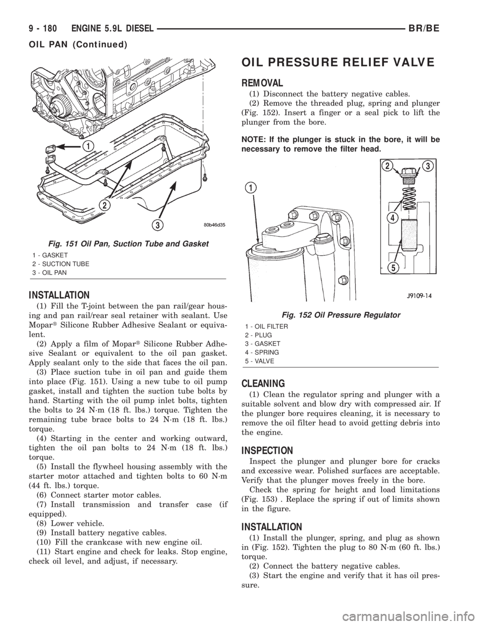
(3) Place suction tube in oil pan and guide them
into place (Fig. 151). Using a new tube to oil pump
gasket, install and tighten the suction tube bolts by
hand. Starting with the oil pump inlet bolts, tighten
the bolts to 24 N´m (18 ft. lbs.) torque. Tighten the
remaining tube brace bolts to 24 N´m (18 ft. lbs.)
torque.
(4) Starting in the center and working outward,
tighten the oil pan bolts to 24 N´m (18 ft. lbs.)
torque.
(5) Install the flywheel housing assembly with the
starter motor attached and tighten bolts to 60 N´m
(44 ft. lbs.) torque.
(6) Connect starter motor cables.
(7) Install transmission and transfer case (if
equipped).
(8) Lower vehicle.
(9) Install battery negative cables.
(10) Fill the crankcase with new engine oil.
(11) Start engine and check for leaks. Stop engine,
check oil level, and adjust, if necessary.
OIL PRESSURE RELIEF VALVE
REMOVAL
(1) Disconnect the battery negative cables.
(2) Remove the threaded plug, spring and plunger
(Fig. 152). Insert a finger or a seal pick to lift the
plunger from the bore.
NOTE: If the plunger is stuck in the bore, it will be
necessary to remove the filter head.
CLEANING
(1) Clean the regulator spring and plunger with a
suitable solvent and blow dry with compressed air. If
the plunger bore requires cleaning, it is necessary to
remove the oil filter head to avoid getting debris into
the engine.
INSPECTION
Inspect the plunger and plunger bore for cracks
and excessive wear. Polished surfaces are acceptable.
Verify that the plunger moves freely in the bore.
Check the spring for height and load limitations
(Fig. 153) . Replace the spring if out of limits shown
in the figure.
INSTALLATION
(1) Install the plunger, spring, and plug as shown
in (Fig. 152). Tighten the plug to 80 N´m (60 ft. lbs.)
torque.
(2) Connect the battery negative cables.
(3) Start the engine and verify that it has oil pres-
sure.
Fig. 151 Oil Pan, Suction Tube and Gasket
1 - GASKET
2 - SUCTION TUBE
3 - OIL PAN
Fig. 152 Oil Pressure Regulator
1 - OIL FILTER
2 - PLUG
3 - GASKET
4 - SPRING
5 - VALVE
9 - 180 ENGINE 5.9L DIESELBR/BE
OIL PAN (Continued)
Page 1261 of 2255
INSPECTION
Inspect the exhaust manifold for cracks. Measure
the exhaust manifold for flatness. Place a ruler over
all of the exhaust ports and insert a feeler gauge
between the port flange and the ruler.
INSTALLATION
(1) Using new gaskets, install the exhaust mani-
fold and gaskets. Install the bolts and spacers and
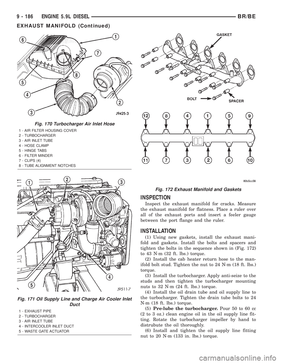
tighten the bolts in the sequence shown in (Fig. 172)
to 43 N´m (32 ft. lbs.) torque.
(2) Install the cab heater return hose to the man-
ifold bolt stud. Tighten the nut to 24 N´m (18 ft. lbs.)
torque.
(3) Install the turbocharger. Apply anti-seize to the
studs and then tighten the turbocharger mounting
nuts to 32 N´m (24 ft. lbs.) torque.
(4) Install the oil drain tube and oil supply line to
the turbocharger. Tighten the drain tube bolts to 24
N´m (18 ft. lbs.) torque.
(5)Pre-lube the turbocharger.Pour 50 to 60 cc
(2 to 3 oz.) clean engine oil in the oil supply line fit-
ting. Rotate the turbocharger impeller by hand to
distrubute the oil thoroughly.
(6) Install and tighten the oil supply line fitting
nut to 20 N´m (133 in. lbs.) torque.
Fig. 170 Turbocharger Air Inlet Hose
1 - AIR FILTER HOUSING COVER
2 - TURBOCHARGER
3 - AIR INLET TUBE
4 - HOSE CLAMP
5 - HINGE TABS
6 - FILTER MINDER
7 - CLIPS (4)
8 - TUBE ALIGNMENT NOTCHES
Fig. 171 Oil Supply Line and Charge Air Cooler Inlet
Duct
1 - EXHAUST PIPE
2 - TURBOCHARGER
3 - AIR INLET TUBE
4 - INTERCOOLER INLET DUCT
5 - WASTE GATE ACTUATOR
Fig. 172 Exhaust Manifold and Gaskets
9 - 186 ENGINE 5.9L DIESELBR/BE
EXHAUST MANIFOLD (Continued)
Page 1282 of 2255
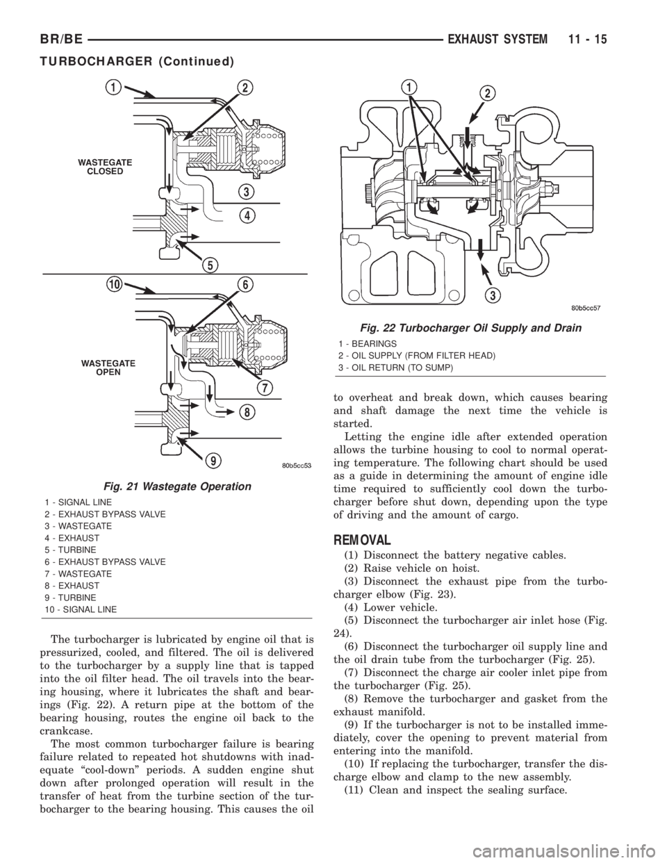
The turbocharger is lubricated by engine oil that is
pressurized, cooled, and filtered. The oil is delivered
to the turbocharger by a supply line that is tapped
into the oil filter head. The oil travels into the bear-
ing housing, where it lubricates the shaft and bear-
ings (Fig. 22). A return pipe at the bottom of the
bearing housing, routes the engine oil back to the
crankcase.
The most common turbocharger failure is bearing
failure related to repeated hot shutdowns with inad-
equate ªcool-downº periods. A sudden engine shut
down after prolonged operation will result in the
transfer of heat from the turbine section of the tur-
bocharger to the bearing housing. This causes the oilto overheat and break down, which causes bearing
and shaft damage the next time the vehicle is
started.
Letting the engine idle after extended operation
allows the turbine housing to cool to normal operat-
ing temperature. The following chart should be used
as a guide in determining the amount of engine idle
time required to sufficiently cool down the turbo-
charger before shut down, depending upon the type
of driving and the amount of cargo.
REMOVAL
(1) Disconnect the battery negative cables.
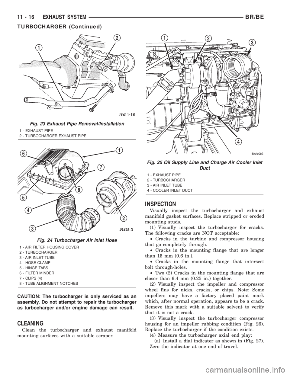
(2) Raise vehicle on hoist.
(3) Disconnect the exhaust pipe from the turbo-
charger elbow (Fig. 23).
(4) Lower vehicle.
(5) Disconnect the turbocharger air inlet hose (Fig.
24).
(6) Disconnect the turbocharger oil supply line and
the oil drain tube from the turbocharger (Fig. 25).
(7) Disconnect the charge air cooler inlet pipe from
the turbocharger (Fig. 25).
(8) Remove the turbocharger and gasket from the
exhaust manifold.
(9) If the turbocharger is not to be installed imme-
diately, cover the opening to prevent material from
entering into the manifold.
(10) If replacing the turbocharger, transfer the dis-
charge elbow and clamp to the new assembly.
(11) Clean and inspect the sealing surface.
Fig. 21 Wastegate Operation
1 - SIGNAL LINE
2 - EXHAUST BYPASS VALVE
3 - WASTEGATE
4 - EXHAUST
5 - TURBINE
6 - EXHAUST BYPASS VALVE
7 - WASTEGATE
8 - EXHAUST
9 - TURBINE
10 - SIGNAL LINE
Fig. 22 Turbocharger Oil Supply and Drain
1 - BEARINGS
2 - OIL SUPPLY (FROM FILTER HEAD)
3 - OIL RETURN (TO SUMP)
BR/BEEXHAUST SYSTEM 11 - 15
TURBOCHARGER (Continued)
Page 1283 of 2255
CAUTION: The turbocharger is only serviced as an
assembly. Do not attempt to repair the turbocharger
as turbocharger and/or engine damage can result.
CLEANING
Clean the turbocharger and exhaust manifold
mounting surfaces with a suitable scraper.
INSPECTION
Visually inspect the turbocharger and exhaust
manifold gasket surfaces. Replace stripped or eroded
mounting studs.
(1) Visually inspect the turbocharger for cracks.
The following cracks are NOT acceptable:
²Cracks in the turbine and compressor housing
that go completely through.
²Cracks in the mounting flange that are longer
than 15 mm (0.6 in.).
²Cracks in the mounting flange that intersect
bolt through-holes.
²Two (2) Cracks in the mounting flange that are
closer than 6.4 mm (0.25 in.) together.
(2) Visually inspect the impeller and compressor
wheel fins for nicks, cracks, or chips. Note: Some
impellers may have a factory placed paint mark
which, after normal operation, appears to be a crack.
Remove this mark with a suitable solvent to verify
that it is not a crack.
(3) Visually inspect the turbocharger compressor
housing for an impeller rubbing condition (Fig. 26).
Replace the turbocharger if the condition exists.
(4) Measure the turbocharger axial end play:
(a) Install a dial indicator as shown in (Fig. 27).
Zero the indicator at one end of travel.
Fig. 23 Exhaust Pipe Removal/Installation
1 - EXHAUST PIPE
2 - TURBOCHARGER EXHAUST PIPE
Fig. 24 Turbocharger Air Inlet Hose
1 - AIR FILTER HOUSING COVER
2 - TURBOCHARGER
3 - AIR INLET TUBE
4 - HOSE CLAMP
5 - HINGE TABS
6 - FILTER MINDER
7 - CLIPS (4)
8 - TUBE ALIGNMENT NOTCHES
Fig. 25 Oil Supply Line and Charge Air Cooler Inlet
Duct
1 - EXHAUST PIPE
2 - TURBOCHARGER
3 - AIR INLET TUBE
4 - COOLER INLET DUCT
11 - 16 EXHAUST SYSTEMBR/BE
TURBOCHARGER (Continued)