2002 DODGE RAM glove box
[x] Cancel search: glove boxPage 846 of 2255
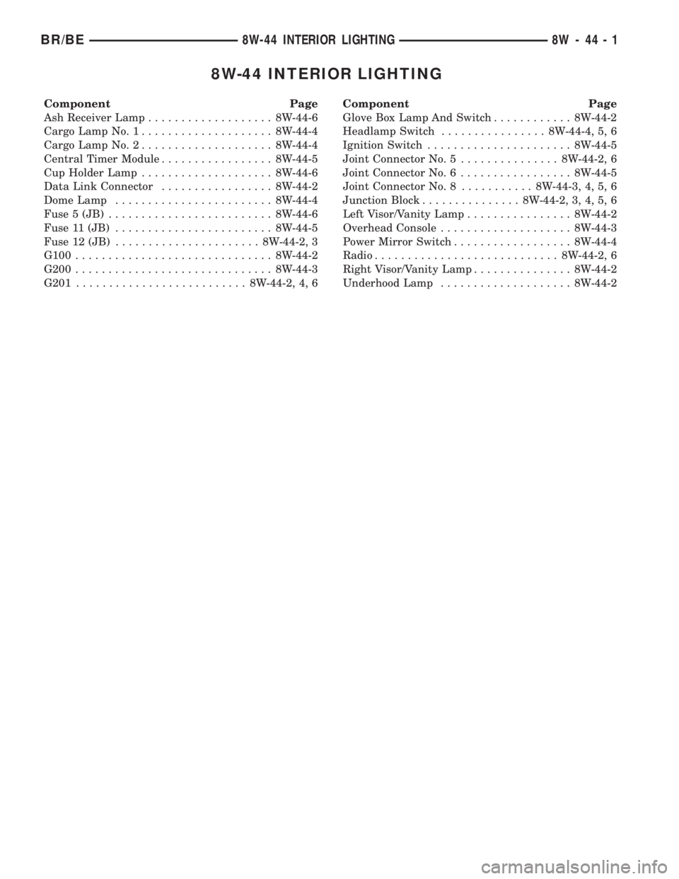
8W-44 INTERIOR LIGHTING
Component Page
Ash Receiver Lamp................... 8W-44-6
Cargo Lamp No. 1.................... 8W-44-4
Cargo Lamp No. 2.................... 8W-44-4
Central Timer Module................. 8W-44-5
Cup Holder Lamp.................... 8W-44-6
Data Link Connector................. 8W-44-2
Dome Lamp........................ 8W-44-4
Fuse 5 (JB)......................... 8W-44-6
Fuse 11 (JB)........................ 8W-44-5
Fuse 12 (JB)...................... 8W-44-2, 3
G100.............................. 8W-44-2
G200.............................. 8W-44-3
G201.......................... 8W-44-2, 4, 6Component Page
Glove Box Lamp And Switch............ 8W-44-2
Headlamp Switch................ 8W-44-4, 5, 6
Ignition Switch...................... 8W-44-5
Joint Connector No. 5............... 8W-44-2, 6
Joint Connector No. 6................. 8W-44-5
Joint Connector No. 8........... 8W-44-3, 4, 5, 6
Junction Block............... 8W-44-2, 3, 4, 5, 6
Left Visor/Vanity Lamp................ 8W-44-2
Overhead Console.................... 8W-44-3
Power Mirror Switch.................. 8W-44-4
Radio............................ 8W-44-2, 6
Right Visor/Vanity Lamp............... 8W-44-2
Underhood Lamp.................... 8W-44-2
BR/BE8W-44 INTERIOR LIGHTING 8W - 44 - 1
Page 937 of 2255

Component Page
Clutch Pedal Position Switch (M/T)..... 8W-80-35
Controller Antilock Brake C1.......... 8W-80-35
Controller Antilock Brake C2 (ABS)..... 8W-80-35
Crankshaft Position Sensor (Gas 8.0L) . . . 8W-80-36
Crankshaft Position Sensor
(Gas Except 8.0L)................. 8W-80-36
Cummins Bus (Diesel)............... 8W-80-36
Cup Holder Lamp................... 8W-80-36
Data Link Connector................. 8W-80-36
Daytime Running Lamp Module........ 8W-80-37
Dome Lamp....................... 8W-80-37
Driver Airbag...................... 8W-80-37
Driver Cylinder Lock Switch........... 8W-80-37
Driver Door Ajar Switch (Base)......... 8W-80-38
Driver Door Ajar Switch (Premium)..... 8W-80-38
Driver Door Lock Motor.............. 8W-80-38
Driver Door Window/Lock Switch....... 8W-80-38
Driver Heated Seat Cushion........... 8W-80-38
Driver Heated Seat Switch............ 8W-80-39
Driver Lumbar Motor................ 8W-80-39
Driver Power Seat Front Vertical Motor
(Club Cab)....................... 8W-80-39
Driver Power Seat Front Vertical Motor
(Standard Cab)................... 8W-80-39
Driver Power Seat Horizontal Motor
(Club Cab)....................... 8W-80-39
Driver Power Seat Horizontal Motor
(Standard Cab)................... 8W-80-40
Driver Power Seat Rear Vertical Motor
(Club Cab)....................... 8W-80-40
Driver Power Seat Rear Vertical Motor
(Standard Cab)................... 8W-80-40
Driver Power Seat Switch (Club Cab).... 8W-80-40
Driver Power Seat Switch
(Standard Cab)................... 8W-80-41
Driver Power Window Motor........... 8W-80-41
Electric Brake Provision.............. 8W-80-41
Engine Control Module (Diesel)........ 8W-80-41
Engine Coolant Temperature Sensor
(Diesel)......................... 8W-80-42
Engine Coolant Temperature Sensor
(Gas)........................... 8W-80-43
Engine Oil Pressure Sensor (Diesel)..... 8W-80-43
Engine Oil Pressure Sensor (Gas)....... 8W-80-43
EVAP/Purge Solenoid................ 8W-80-43
Front Washer Pump................. 8W-80-43
Fuel Heater (Diesel)................. 8W-80-43
Fuel Injection Pump (Diesel)........... 8W-80-44
Fuel Injector No. 1.................. 8W-80-44
Fuel Injector No. 2.................. 8W-80-44
Fuel Injector No. 3.................. 8W-80-44
Fuel Injector No. 4.................. 8W-80-44
Fuel Injector No. 5.................. 8W-80-45
Fuel Injector No. 6.................. 8W-80-45
Fuel Injector No. 7 (5.2L/5.9L/8.0L)..... 8W-80-45Component Page
Fuel Injector No. 8 (5.2L/5.9L/8.0L)..... 8W-80-45
Fuel Injector No. 9 (8.0L)............. 8W-80-45
Fuel Injector No. 10 (8.0L)............ 8W-80-46
Fuel Pump Module (Gas)............. 8W-80-46
Fuel Tank Module (Diesel)............ 8W-80-46
Fuel Transfer Pump (Diesel)........... 8W-80-46
G300............................. 8W-80-46
Generator......................... 8W-80-47
Glove Box Lamp And Switch........... 8W-80-47
Headlamp Switch C1................ 8W-80-47
Headlamp Switch C2................ 8W-80-47
Heated Mirror Switch................ 8W-80-48
High Note Horn.................... 8W-80-48
Idle Air Control Motor................ 8W-80-48
Ignition Coil (3.9L/5.2L/5.9L).......... 8W-80-48
Ignition Coil 4 Pack (8.0L)............ 8W-80-48
Ignition Coil 6 Pack (8.0L)............ 8W-80-49
Ignition Switch C1.................. 8W-80-49
Ignition Switch C2.................. 8W-80-49
Instrument Cluster C1............... 8W-80-49
Instrument Cluster C2............... 8W-80-50
Intake Air Heater Relays (Diesel)....... 8W-80-50
Intake Air Temperature Sensor (Diesel) . . 8W-80-50
Intake Air Temperature Sensor (Gas).... 8W-80-50
Joint Connector No. 1 (In PDC)........ 8W-80-50
Joint Connector No. 2 (In PDC)........ 8W-80-51
Joint Connector No. 5................ 8W-80-52
Joint Connector No. 6................ 8W-80-52
Joint Connector No. 7................ 8W-80-53
Joint Connector No. 8................ 8W-80-53
Junction Block C1................... 8W-80-54
Junction Block C2................... 8W-80-54
Junction Block C3................... 8W-80-54
Junction Block C4................... 8W-80-55
Junction Block C5................... 8W-80-55
Junction Block C6................... 8W-80-55
Junction Block C7................... 8W-80-55
Junction Block C8................... 8W-80-56
Junction Block C9................... 8W-80-56
Leak Detection Pump (Gas)........... 8W-80-56
Left Back-Up Lamp.................. 8W-80-57
Left Fog Lamp..................... 8W-80-57
Left Front Door Speaker (Premium)..... 8W-80-57
Left Front Door Speaker (Standard)..... 8W-80-57
Left Front Fender Lamp
(Dual Rear Wheels)................ 8W-80-57
Left Front Wheel Speed Sensor (ABS) . . . 8W-80-58
Left Headlamp..................... 8W-80-58
Left License Lamp.................. 8W-80-58
Left Outboard Clearance Lamp......... 8W-80-58
Left Outboard Headlamp............. 8W-80-58
Left Outboard Identification Lamp...... 8W-80-59
Left Park/Turn Signal Lamp........... 8W-80-59
Left Power Mirror................... 8W-80-59
8W - 80 - 2 8W-80 CONNECTOR PIN-OUTSBR/BE
Page 982 of 2255
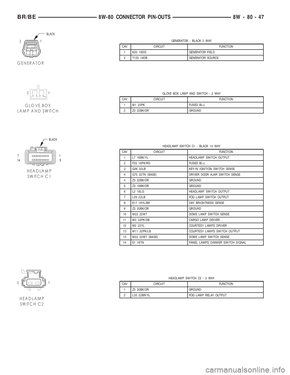
GENERATOR - BLACK 2 WAY
CAV CIRCUIT FUNCTION
1 K20 18DG GENERATOR FIELD
2 T125 18DB GENERATOR SOURCE
GLOVE BOX LAMP AND SWITCH-2WAY
CAV CIRCUIT FUNCTION
1 M1 22PK FUSED B(+)
2 Z3 22BK/OR GROUND
HEADLAMP SWITCH C1 - BLACK 14 WAY
CAV CIRCUIT FUNCTION
1 L7 16BK/YL HEADLAMP SWITCH OUTPUT
2 F33 16PK/RD FUSED B(+)
3 G26 22LB KEY-IN IGNITION SWITCH SENSE
4 G75 22TN (BASE) DRIVER DOOR AJAR SWITCH SENSE
4 Z3 22BK/OR GROUND
5 Z3 18BK/OR GROUND
6 L2 18LG HEADLAMP SWITCH OUTPUT
7 L39 22LB FOG LAMP SWITCH OUTPUT
8 E17 18YL/BK DAY BRIGHTNESS SENSE
9 Z3 20BK/OR GROUND
10 M22 22WT DOME LAMP SWITCH SENSE
11 M3 22PK/DB CARGO LAMP DRIVER
12 M2 22YL COURTESY LAMPS DRIVER
13 M11 22PK/LB COURTESY LAMPS SWITCH OUTPUT
13 M22 22WT (BASE) DOME LAMP SWITCH SENSE
14 E1 18TN PANEL LAMPS DIMMER SWITCH SIGNAL
HEADLAMP SWITCH C2-2WAY
CAV CIRCUIT FUNCTION
1 Z3 20BK/OR GROUND
2 L35 22BR/YL FOG LAMP RELAY OUTPUT
BR/BE8W-80 CONNECTOR PIN-OUTS 8W - 80 - 47
Page 1021 of 2255
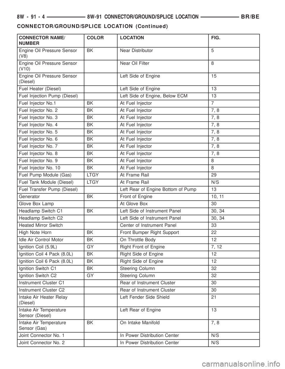
CONNECTOR NAME/
NUMBERCOLOR LOCATION FIG.
Engine Oil Pressure Sensor
(V8)BK Near Distributor 5
Engine Oil Pressure Sensor
(V10)Near Oil Filter 8
Engine Oil Pressure Sensor
(Diesel)Left Side of Engine 15
Fuel Heater (Diesel) Left Side of Engine 13
Fuel Injection Pump (Diesel) Left Side of Engine, Below ECM 13
Fuel Injector No.1 BK At Fuel Injector 7
Fuel Injector No. 2 BK At Fuel Injector 7, 8
Fuel Injector No. 3 BK At Fuel Injector 7, 8
Fuel Injector No. 4 BK At Fuel Injector 7, 8
Fuel Injector No. 5 BK At Fuel Injector 7, 8
Fuel Injector No. 6 BK At Fuel Injector 7, 8
Fuel Injector No. 7 BK At Fuel Injector 7, 8
Fuel Injector No. 8 BK At Fuel Injector 7, 8
Fuel Injector No. 9 BK At Fuel Injector 8
Fuel Injector No. 10 BK At Fuel Injector 8
Fuel Pump Module (Gas) LTGY At Frame Rail 29
Fuel Tank Module (Diesel) LTGY At Frame Rail N/S
Fuel Transfer Pump (Diesel) Left Rear of Engine Bottom of Pump 13
Generator BK Front of Engine 10, 11
Glove Box Lamp At Glove Box 30
Headlamp Switch C1 BK Left Side of Instrument Panel 30, 34
Headlamp Switch C2 Left Side of Instrument Panel 30, 34
Heated Mirror Switch Center of Instrument Panel 33
High Note Horn BK Front Bumper Right Support 22
Idle Air Control Motor BK On Throttle Body 12
Ignition Coil (5.9L) GY Right Front of Engine 7, 12
Ignition Coil 4 Pack (8.0L) BK Right Side of Engine 12
Ignition Coil 6 Pack (8.0L) BK Right Side of Engine 12
Ignition Switch C1 BK Steering Column 32
Ignition Switch C2 GY Steering Column 32
Instrument Cluster C1 Rear of Instrument Cluster 30
Instrument Cluster C2 Rear of Instrument Cluster 30
Intake Air Heater Relay
(Diesel)Left Fender Side Shield 21
Intake Air Temperature
Sensor (Diesel)Left Rear of Engine 13
Intake Air Temperature
Sensor (Gas)BK On Intake Manifold 7, 8
Joint Connector No. 1 In Power Distribution Center N/S
Joint Connector No. 2 In Power Distribution Center N/S
8W - 91 - 4 8W-91 CONNECTOR/GROUND/SPLICE LOCATIONBR/BE
CONNECTOR/GROUND/SPLICE LOCATION (Continued)
Page 1023 of 2255
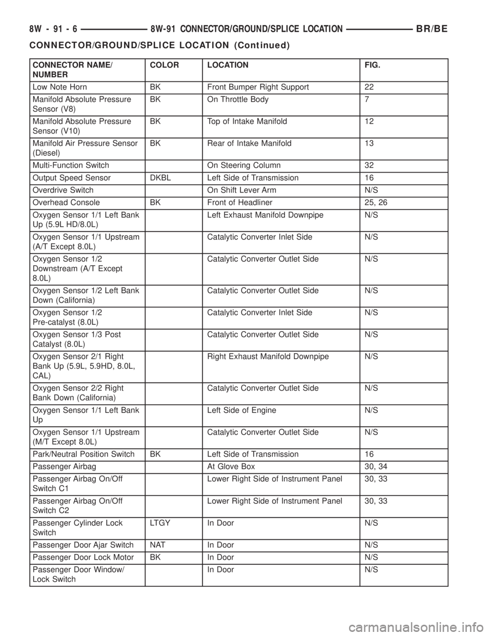
CONNECTOR NAME/
NUMBERCOLOR LOCATION FIG.
Low Note Horn BK Front Bumper Right Support 22
Manifold Absolute Pressure
Sensor (V8)BK On Throttle Body 7
Manifold Absolute Pressure
Sensor (V10)BK Top of Intake Manifold 12
Manifold Air Pressure Sensor
(Diesel)BK Rear of Intake Manifold 13
Multi-Function Switch On Steering Column 32
Output Speed Sensor DKBL Left Side of Transmission 16
Overdrive Switch On Shift Lever Arm N/S
Overhead Console BK Front of Headliner 25, 26
Oxygen Sensor 1/1 Left Bank
Up (5.9L HD/8.0L)Left Exhaust Manifold Downpipe N/S
Oxygen Sensor 1/1 Upstream
(A/T Except 8.0L)Catalytic Converter Inlet Side N/S
Oxygen Sensor 1/2
Downstream (A/T Except
8.0L)Catalytic Converter Outlet Side N/S
Oxygen Sensor 1/2 Left Bank
Down (California)Catalytic Converter Outlet Side N/S
Oxygen Sensor 1/2
Pre-catalyst (8.0L)Catalytic Converter Inlet Side N/S
Oxygen Sensor 1/3 Post
Catalyst (8.0L)Catalytic Converter Outlet Side N/S
Oxygen Sensor 2/1 Right
Bank Up (5.9L, 5.9HD, 8.0L,
CAL)Right Exhaust Manifold Downpipe N/S
Oxygen Sensor 2/2 Right
Bank Down (California)Catalytic Converter Outlet Side N/S
Oxygen Sensor 1/1 Left Bank
UpLeft Side of Engine N/S
Oxygen Sensor 1/1 Upstream
(M/T Except 8.0L)Catalytic Converter Outlet Side N/S
Park/Neutral Position Switch BK Left Side of Transmission 16
Passenger Airbag At Glove Box 30, 34
Passenger Airbag On/Off
Switch C1Lower Right Side of Instrument Panel 30, 33
Passenger Airbag On/Off
Switch C2Lower Right Side of Instrument Panel 30, 33
Passenger Cylinder Lock
SwitchLTGY In Door N/S
Passenger Door Ajar Switch NAT In Door N/S
Passenger Door Lock Motor BK In Door N/S
Passenger Door Window/
Lock SwitchIn Door N/S
8W - 91 - 6 8W-91 CONNECTOR/GROUND/SPLICE LOCATIONBR/BE
CONNECTOR/GROUND/SPLICE LOCATION (Continued)
Page 1060 of 2255
8W-97 POWER DISTRIBUTION
TABLE OF CONTENTS
page page
POWER DISTRIBUTION
DESCRIPTION..........................1
OPERATION............................1
SPECIAL TOOLS
POWER DISTRIBUTION SYSTEMS.........2
CIGAR LIGHTER OUTLET
DESCRIPTION..........................2
OPERATION............................2
DIAGNOSIS AND TESTING - CIGAR LIGHTER
OUTLET.............................2
REMOVAL.............................3
INSTALLATION..........................4
CIRCUIT BREAKER
DESCRIPTION..........................4
DIAGNOSIS AND TESTING - CIRCUIT
BREAKER............................4
GENERATOR CARTRIDGE FUSE
DESCRIPTION..........................4
OPERATION............................4
REMOVAL.............................4
INSTALLATION..........................4
IOD FUSE
DESCRIPTION..........................5
OPERATION............................5
REMOVAL.............................6
INSTALLATION..........................6
JUNCTION BLOCK
DESCRIPTION..........................6
OPERATION............................7
DIAGNOSIS AND TESTING - JUNCTION
BLOCK..............................7
REMOVAL.............................7
INSTALLATION..........................8POWER DISTRIBUTION CENTER
DESCRIPTION..........................8
OPERATION............................8
REMOVAL.............................8
INSTALLATION.........................10
POWER OUTLET
DESCRIPTION.........................10
OPERATION...........................10
DIAGNOSIS AND TESTING - POWER OUTLET . 10
REMOVAL.............................11
INSTALLATION.........................11
HORN RELAY
DESCRIPTION.........................12
DIAGNOSIS AND TESTING - HORN RELAY . . . 12
REMOVAL.............................12
INSTALLATION.........................12
HEADLAMP RELAY
DESCRIPTION.........................13
REMOVAL.............................13
INSTALLATION.........................13
MICRO-RELAY
DESCRIPTION.........................13
OPERATION...........................14
DIAGNOSIS AND TESTING - MICRO-RELAY . . 14
REMOVAL.............................14
INSTALLATION.........................14
RELAY
DESCRIPTION.........................14
OPERATION...........................14
DIAGNOSIS AND TESTING - RELAY.........15
REMOVAL.............................15
INSTALLATION.........................15
POWER DISTRIBUTION
DESCRIPTION
This group covers the various standard and
optional power distribution components used on this
model. The power distribution system for this vehicle
consists of the following components:
²Power Distribution Center (PDC)
²Junction Block (JB).
The power distribution system also incorporates
various types of circuit control and protection fea-
tures, including:
²Automatic resetting circuit breakers
²Blade-type fuses²Cartridge fuses
²Circuit splice blocks
²Flashers
²Relays.
Following are general descriptions of the major
components in the power distribution system. See the
owner's manual in the vehicle glove box for more
information on the features and use of all of the
power distribution system components. Refer toWir-
ing Diagramsfor complete circuit diagrams for the
various power distribution system components.
OPERATION
The power distribution system for this vehicle is
designed to provide safe, reliable, and centralized dis-
BR/BE8W-97 POWER DISTRIBUTION 8W - 97 - 1
Page 1064 of 2255
to service. Refer toCharging Systemin the index of
this service manual for the charging system diagnos-
tic procedures.
(1) Position the generator cartridge fuse onto the
two B(+) terminal stud bus bars within the PDC.
(2) Install and tighten the two screws that secure
the generator cartridge fuse to the two B(+) terminal
stud bus bars within the PDC. Tighten the screws to
3.4 N´m (30 in. lbs.).Be certain that both screws
are tightened to the proper torque value.
(3) Install and latch the cover onto the PDC.
(4) Reconnect the battery negative cable.
IOD FUSE
DESCRIPTION
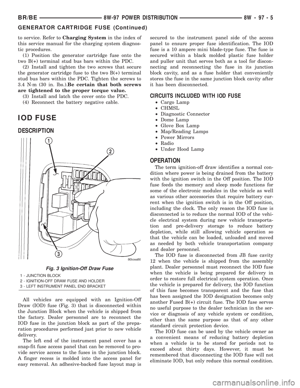
All vehicles are equipped with an Ignition-Off
Draw (IOD) fuse (Fig. 3) that is disconnected within
the Junction Block when the vehicle is shipped from
the factory. Dealer personnel are to reconnect the
IOD fuse in the junction block as part of the prepa-
ration procedures performed just prior to new vehicle
delivery.
The left end of the instrument panel cover has a
snap-fit fuse access panel that can be removed to pro-
vide service access to the fuses in the junction block.
A finger recess is molded into the access panel for
easy removal. An adhesive-backed fuse layout map issecured to the instrument panel side of the access
panel to ensure proper fuse identification. The IOD
fuse is a 10 ampere mini blade-type fuse. The fuse is
secured within a black molded plastic fuse holder
and puller unit that serves both as a tool for discon-
necting and reconnecting the fuse in its junction
block cavity, and as a fuse holder that conveniently
stores the fuse in the same junction block cavity after
it has been disconnected.
CIRCUITS INCLUDED WITH IOD FUSE
²Cargo Lamp
²CHMSL
²Diagnostic Connector
²Dome Lamp
²Glove Box Lamp
²Map/Reading Lamps
²Power Mirrors
²Radio
²Under Hood Lamp
OPERATION
The term ignition-off draw identifies a normal con-
dition where power is being drained from the battery
with the ignition switch in the Off position. The IOD
fuse feeds the memory and sleep mode functions for
some of the electronic modules in the vehicle as well
as various other accessories that require battery cur-
rent when the ignition switch is in the Off position,
including the clock. The only reason the IOD fuse is
disconnected is to reduce the normal IOD of the vehi-
cle electrical system during new vehicle transporta-
tion and pre-delivery storage to reduce battery
depletion, while still allowing vehicle operation so
that the vehicle can be loaded, unloaded and moved
as needed by both vehicle transportation company
and dealer personnel.
The IOD fuse is disconnected from JB fuse cavity
12 when the vehicle is shipped from the assembly
plant. Dealer personnel must reconnect the IOD fuse
when the vehicle is being prepared for delivery in
order to restore full electrical system operation. Once
the vehicle is prepared for delivery, the IOD function
of this fuse becomes transparent and the fuse that
has been assigned the IOD designation becomes only
another Fused B(+) circuit fuse. The IOD fuse serves
no useful purpose to the dealer technician in the ser-
vice or diagnosis of any vehicle system or condition,
other than the same purpose as that of any other
standard circuit protection device.
The IOD fuse can be used by the vehicle owner as
a convenient means of reducing battery depletion
when a vehicle is to be stored for periods not to
exceed about thirty days. However, it must be
remembered that disconnecting the IOD fuse will not
eliminate IOD, but only reduce this normal condition.
Fig. 3 Ignition-Off Draw Fuse
1 - JUNCTION BLOCK
2 - IGNITION-OFF DRAW FUSE AND HOLDER
3 - LEFT INSTRUMENT PANEL END BRACKET
BR/BE8W-97 POWER DISTRIBUTION 8W - 97 - 5
GENERATOR CARTRIDGE FUSE (Continued)
Page 2029 of 2255
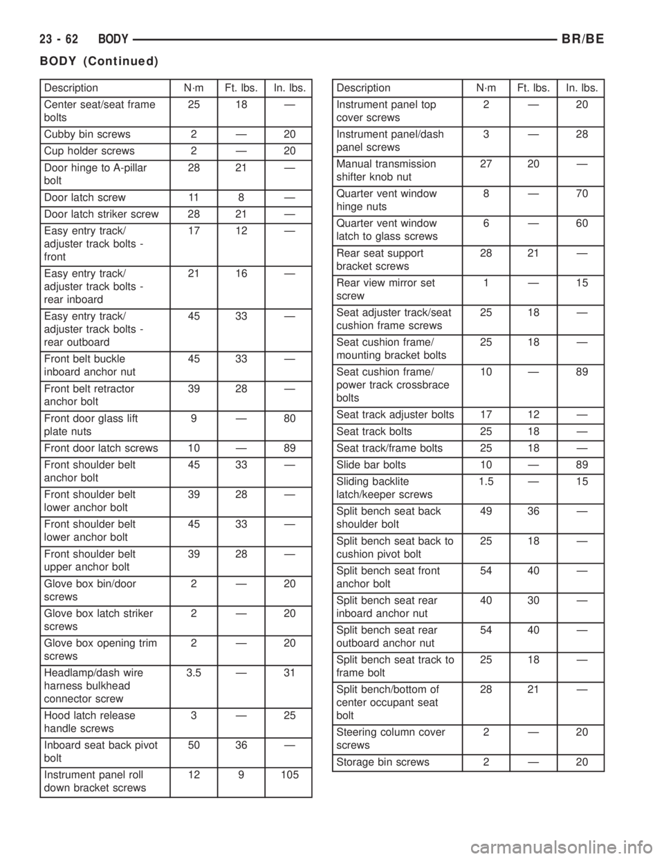
Description N´m Ft. lbs. In. lbs.
Center seat/seat frame
bolts25 18 Ð
Cubby bin screws 2 Ð 20
Cup holder screws 2 Ð 20
Door hinge to A-pillar
bolt28 21 Ð
Door latch screw 11 8 Ð
Door latch striker screw 28 21 Ð
Easy entry track/
adjuster track bolts -
front17 12 Ð
Easy entry track/
adjuster track bolts -
rear inboard21 16 Ð
Easy entry track/
adjuster track bolts -
rear outboard45 33 Ð
Front belt buckle
inboard anchor nut45 33 Ð
Front belt retractor
anchor bolt39 28 Ð
Front door glass lift
plate nuts9Ð80
Front door latch screws 10 Ð 89
Front shoulder belt
anchor bolt45 33 Ð
Front shoulder belt
lower anchor bolt39 28 Ð
Front shoulder belt
lower anchor bolt45 33 Ð
Front shoulder belt
upper anchor bolt39 28 Ð
Glove box bin/door
screws2Ð20
Glove box latch striker
screws2Ð20
Glove box opening trim
screws2Ð20
Headlamp/dash wire
harness bulkhead
connector screw3.5 Ð 31
Hood latch release
handle screws3Ð25
Inboard seat back pivot
bolt50 36 Ð
Instrument panel roll
down bracket screws12 9 105Description N´m Ft. lbs. In. lbs.
Instrument panel top
cover screws2Ð20
Instrument panel/dash
panel screws3Ð28
Manual transmission
shifter knob nut27 20 Ð
Quarter vent window
hinge nuts8Ð70
Quarter vent window
latch to glass screws6Ð60
Rear seat support
bracket screws28 21 Ð
Rear view mirror set
screw1Ð15
Seat adjuster track/seat
cushion frame screws25 18 Ð
Seat cushion frame/
mounting bracket bolts25 18 Ð
Seat cushion frame/
power track crossbrace
bolts10 Ð 89
Seat track adjuster bolts 17 12 Ð
Seat track bolts 25 18 Ð
Seat track/frame bolts 25 18 Ð
Slide bar bolts 10 Ð 89
Sliding backlite
latch/keeper screws1.5 Ð 15
Split bench seat back
shoulder bolt49 36 Ð
Split bench seat back to
cushion pivot bolt25 18 Ð
Split bench seat front
anchor bolt54 40 Ð
Split bench seat rear
inboard anchor nut40 30 Ð
Split bench seat rear
outboard anchor nut54 40 Ð
Split bench seat track to
frame bolt25 18 Ð
Split bench/bottom of
center occupant seat
bolt28 21 Ð
Steering column cover
screws2Ð20
Storage bin screws 2 Ð 20
23 - 62 BODYBR/BE
BODY (Continued)