2002 DODGE RAM window switch
[x] Cancel search: window switchPage 1003 of 2255
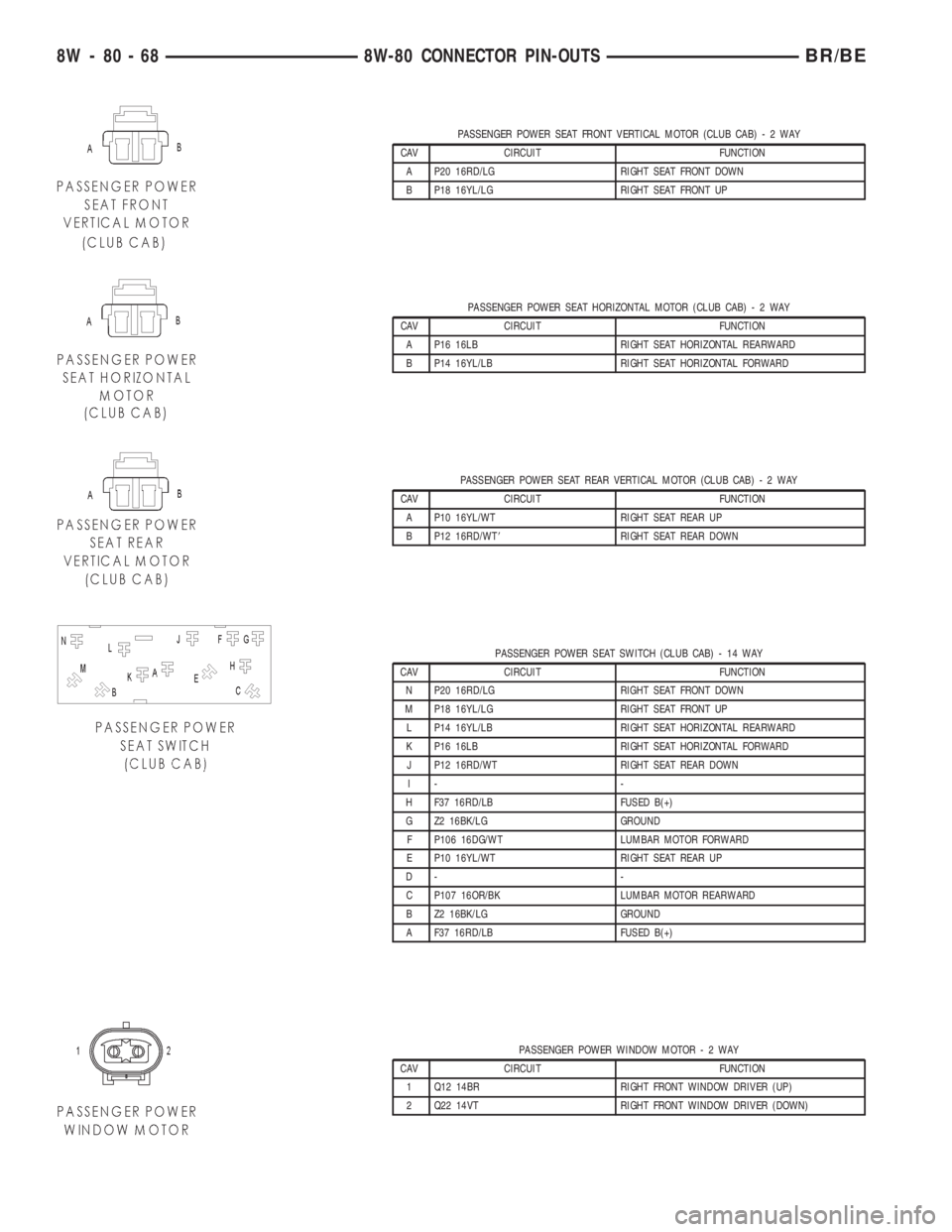
PASSENGER POWER SEAT FRONT VERTICAL MOTOR (CLUB CAB)-2WAY
CAV CIRCUIT FUNCTION
A P20 16RD/LG RIGHT SEAT FRONT DOWN
B P18 16YL/LG RIGHT SEAT FRONT UP
PASSENGER POWER SEAT HORIZONTAL MOTOR (CLUB CAB)-2WAY
CAV CIRCUIT FUNCTION
A P16 16LB RIGHT SEAT HORIZONTAL REARWARD
B P14 16YL/LB RIGHT SEAT HORIZONTAL FORWARD
PASSENGER POWER SEAT REAR VERTICAL MOTOR (CLUB CAB)-2WAY
CAV CIRCUIT FUNCTION
A P10 16YL/WT RIGHT SEAT REAR UP
B P12 16RD/WT8RIGHT SEAT REAR DOWN
PASSENGER POWER SEAT SWITCH (CLUB CAB) - 14 WAY
CAV CIRCUIT FUNCTION
N P20 16RD/LG RIGHT SEAT FRONT DOWN
M P18 16YL/LG RIGHT SEAT FRONT UP
L P14 16YL/LB RIGHT SEAT HORIZONTAL REARWARD
K P16 16LB RIGHT SEAT HORIZONTAL FORWARD
J P12 16RD/WT RIGHT SEAT REAR DOWN
I- -
H F37 16RD/LB FUSED B(+)
G Z2 16BK/LG GROUND
F P106 16DG/WT LUMBAR MOTOR FORWARD
E P10 16YL/WT RIGHT SEAT REAR UP
D- -
C P107 16OR/BK LUMBAR MOTOR REARWARD
B Z2 16BK/LG GROUND
A F37 16RD/LB FUSED B(+)
PASSENGER POWER WINDOW MOTOR-2WAY
CAV CIRCUIT FUNCTION
1 Q12 14BR RIGHT FRONT WINDOW DRIVER (UP)
2 Q22 14VT RIGHT FRONT WINDOW DRIVER (DOWN)
8W - 80 - 68 8W-80 CONNECTOR PIN-OUTSBR/BE
Page 1020 of 2255
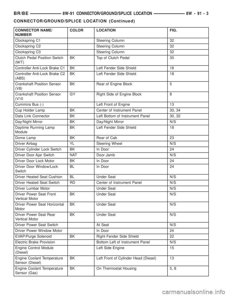
CONNECTOR NAME/
NUMBERCOLOR LOCATION FIG.
Clockspring C1 Steering Column 32
Clockspring C2 Steering Column 32
Clockspring C3 Steering Column 32
Clutch Pedal Position Switch
(M/T)BK Top of Clutch Pedal 35
Controller Anti-Lock Brake C1 BK Left Fender Side Shield 18
Controller Anti-Lock Brake C2
(ABS)BK Left Fender Side Shield 18
Crankshaft Position Sensor
(V8)BK Rear of Engine Block 5
Crankshaft Position Sensor
(V10GY Right Side of Engine Block 8
Cummins Bus (-) Left Front of Engine 13
Cup Holder Lamp BK Center of Instrument Panel 30, 34
Data Link Connector BK Left Bottom of Instrument Panel 30, 32
Day/Night Mirror BK Day/Night Mirror N/S
Daytime Running Lamp
ModuleBK Left Fender Side Shield 18
Dome Lamp BK Rear of Cab 23
Driver Airbag YL Steering Wheel N/S
Driver Cylinder Lock Switch BK In Door 24
Driver Door Ajar Switch NAT Door Jamb N/S
Driver Door Lock Motor BK In Door 24
Driver Door Window/Lock
SwitchBL In Door 24
Driver Heated Seat Cushion BL Under Seat N/S
Driver Heated Seat Switch RD Center of Instrument Panel N/S
Driver Lumbar Motor Under Seat N/S
Driver Power Seat Front
Vertical MotorBK Under Seat N/S
Driver Power Seat Horizontal
MotorBK Under Seat N/S
Driver Power Seat Rear
Vertical MotorBK Under Seat N/S
Driver Power Seat Switch At Seat N/S
Driver Power Window Motor In Door 24
EVAP/Purge Solenoid BK Right Fender Side Shield 22
Electric Brake Provision Bottom Left of Instrument Panel N/S
Engine Control Module
(Diesel)Left Side Engine 15
Engine Coolant Temperature
Sensor (Diesel)BK Left Front of Cylinder Head (Diesel) 13
Engine Coolant Temperature
Sensor (Gas)BK On Thermostat Housing 5, 8
BR/BE8W-91 CONNECTOR/GROUND/SPLICE LOCATION 8W - 91 - 3
CONNECTOR/GROUND/SPLICE LOCATION (Continued)
Page 1023 of 2255
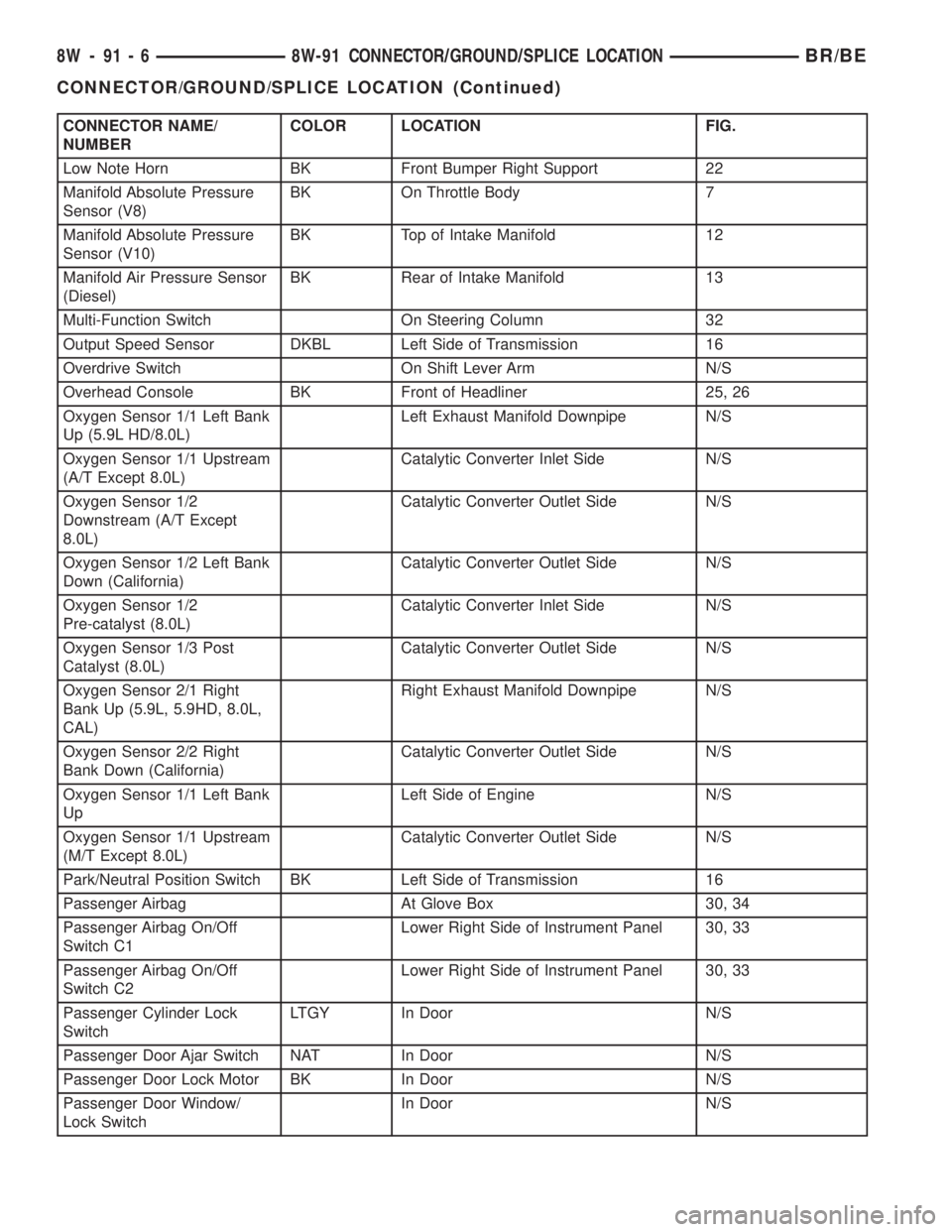
CONNECTOR NAME/
NUMBERCOLOR LOCATION FIG.
Low Note Horn BK Front Bumper Right Support 22
Manifold Absolute Pressure
Sensor (V8)BK On Throttle Body 7
Manifold Absolute Pressure
Sensor (V10)BK Top of Intake Manifold 12
Manifold Air Pressure Sensor
(Diesel)BK Rear of Intake Manifold 13
Multi-Function Switch On Steering Column 32
Output Speed Sensor DKBL Left Side of Transmission 16
Overdrive Switch On Shift Lever Arm N/S
Overhead Console BK Front of Headliner 25, 26
Oxygen Sensor 1/1 Left Bank
Up (5.9L HD/8.0L)Left Exhaust Manifold Downpipe N/S
Oxygen Sensor 1/1 Upstream
(A/T Except 8.0L)Catalytic Converter Inlet Side N/S
Oxygen Sensor 1/2
Downstream (A/T Except
8.0L)Catalytic Converter Outlet Side N/S
Oxygen Sensor 1/2 Left Bank
Down (California)Catalytic Converter Outlet Side N/S
Oxygen Sensor 1/2
Pre-catalyst (8.0L)Catalytic Converter Inlet Side N/S
Oxygen Sensor 1/3 Post
Catalyst (8.0L)Catalytic Converter Outlet Side N/S
Oxygen Sensor 2/1 Right
Bank Up (5.9L, 5.9HD, 8.0L,
CAL)Right Exhaust Manifold Downpipe N/S
Oxygen Sensor 2/2 Right
Bank Down (California)Catalytic Converter Outlet Side N/S
Oxygen Sensor 1/1 Left Bank
UpLeft Side of Engine N/S
Oxygen Sensor 1/1 Upstream
(M/T Except 8.0L)Catalytic Converter Outlet Side N/S
Park/Neutral Position Switch BK Left Side of Transmission 16
Passenger Airbag At Glove Box 30, 34
Passenger Airbag On/Off
Switch C1Lower Right Side of Instrument Panel 30, 33
Passenger Airbag On/Off
Switch C2Lower Right Side of Instrument Panel 30, 33
Passenger Cylinder Lock
SwitchLTGY In Door N/S
Passenger Door Ajar Switch NAT In Door N/S
Passenger Door Lock Motor BK In Door N/S
Passenger Door Window/
Lock SwitchIn Door N/S
8W - 91 - 6 8W-91 CONNECTOR/GROUND/SPLICE LOCATIONBR/BE
CONNECTOR/GROUND/SPLICE LOCATION (Continued)
Page 1024 of 2255
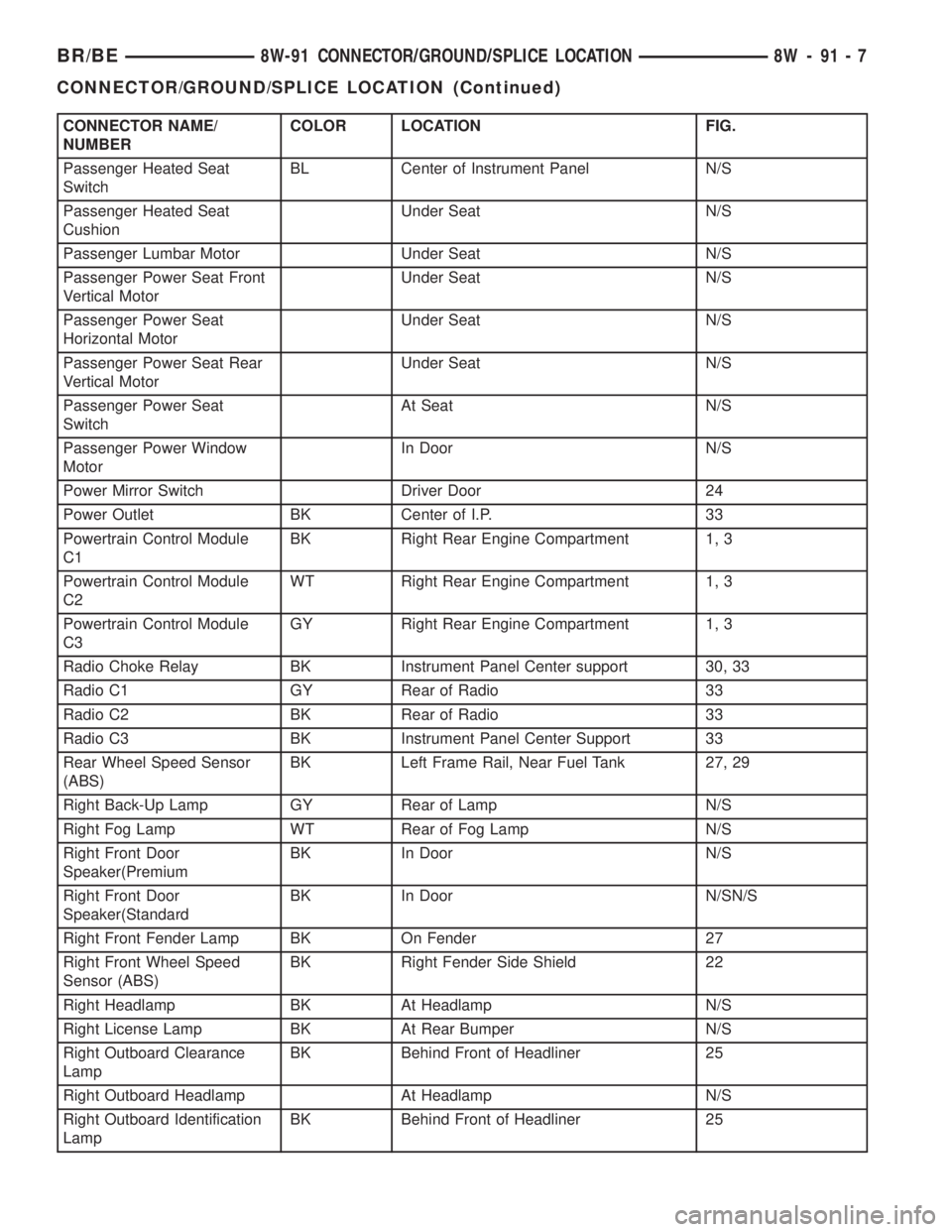
CONNECTOR NAME/
NUMBERCOLOR LOCATION FIG.
Passenger Heated Seat
SwitchBL Center of Instrument Panel N/S
Passenger Heated Seat
CushionUnder Seat N/S
Passenger Lumbar Motor Under Seat N/S
Passenger Power Seat Front
Vertical MotorUnder Seat N/S
Passenger Power Seat
Horizontal MotorUnder Seat N/S
Passenger Power Seat Rear
Vertical MotorUnder Seat N/S
Passenger Power Seat
SwitchAt Seat N/S
Passenger Power Window
MotorIn Door N/S
Power Mirror Switch Driver Door 24
Power Outlet BK Center of I.P. 33
Powertrain Control Module
C1BK Right Rear Engine Compartment 1, 3
Powertrain Control Module
C2WT Right Rear Engine Compartment 1, 3
Powertrain Control Module
C3GY Right Rear Engine Compartment 1, 3
Radio Choke Relay BK Instrument Panel Center support 30, 33
Radio C1 GY Rear of Radio 33
Radio C2 BK Rear of Radio 33
Radio C3 BK Instrument Panel Center Support 33
Rear Wheel Speed Sensor
(ABS)BK Left Frame Rail, Near Fuel Tank 27, 29
Right Back-Up Lamp GY Rear of Lamp N/S
Right Fog Lamp WT Rear of Fog Lamp N/S
Right Front Door
Speaker(PremiumBK In Door N/S
Right Front Door
Speaker(StandardBK In Door N/SN/S
Right Front Fender Lamp BK On Fender 27
Right Front Wheel Speed
Sensor (ABS)BK Right Fender Side Shield 22
Right Headlamp BK At Headlamp N/S
Right License Lamp BK At Rear Bumper N/S
Right Outboard Clearance
LampBK Behind Front of Headliner 25
Right Outboard Headlamp At Headlamp N/S
Right Outboard Identification
LampBK Behind Front of Headliner 25
BR/BE8W-91 CONNECTOR/GROUND/SPLICE LOCATION 8W - 91 - 7
CONNECTOR/GROUND/SPLICE LOCATION (Continued)
Page 2042 of 2255
INSTALLATION
(1) Position flag cover on door.
(2) Install nuts attaching mirror flag cover to door
frame.
(3) Install flag door seal.
(4) Install door trim panel. (Refer to 23 - BODY/
DOOR - FRONT/TRIM PANEL - INSTALLATION)
TRIM PANEL
REMOVAL
(1) Roll window down.
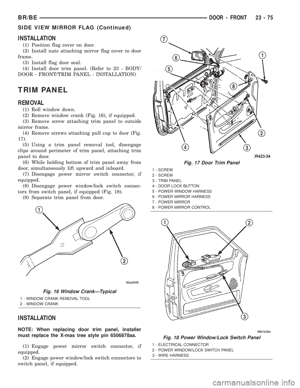
(2) Remove window crank (Fig. 16), if equipped.
(3) Remove screw attaching trim panel to outside
mirror frame.
(4) Remove screws attaching pull cup to door (Fig.
17).
(5) Using a trim panel removal tool, disengage
clips around perimeter of trim panel, attaching trim
panel to door.
(6) While holding bottom of trim panel away from
door, simultaneously lift upward and inboard.
(7) Disengage power mirror switch connector, if
equipped.
(8) Disengage power window/lock switch connec-
tors from switch panel, if equipped (Fig. 18).
(9) Separate trim panel from door.
INSTALLATION
NOTE: When replacing door trim panel, installer
must replace the X-mas tree style pin 6506878aa.
(1) Engage power mirror switch connector, if
equipped.
(2) Engage power window/lock switch connectors to
switch panel, if equipped.
Fig. 16 Window CrankÐTypical
1 - WINDOW CRANK REMOVAL TOOL
2 - WINDOW CRANK
Fig. 17 Door Trim Panel
1 - SCREW
2 - SCREW
3 - TRIM PANEL
4 - DOOR LOCK BUTTON
5 - POWER WINDOW HARNESS
6 - POWER MIRROR HARNESS
7 - POWER MIRROR
8 - POWER MIRROR CONTROL
Fig. 18 Power Window/Lock Switch Panel
1 - ELECTRICAL CONNECTOR
2 - POWER WINDOW/LOCK SWITCH PANEL
3 - WIRE HARNESS
BR/BEDOOR - FRONT 23 - 75
SIDE VIEW MIRROR FLAG (Continued)
Page 2123 of 2255
The optional air conditioner for all models is
designed for the use of non-CFC, R-134a refrigerant.
The air conditioning system has an evaporator to cool
and dehumidify the incoming air prior to blending it
with the heated air. This air conditioning system
uses a fixed orifice tube in the middle of the liquid
line to meter refrigerant flow to the evaporator coil.
To maintain minimum evaporator temperature and
prevent evaporator freezing, the a/c low pressure
switch on the accumulator cycles the compressor
clutch.
OPERATION - REFRIGERANT SYSTEM SERVICE
PORT
The high pressure service port is located on the liq-
uid line between the condenser and the evaporator,
near the front of the engine compartment. The low
pressure service port is located on the suction line,
near the accumulator outlet.
Each of the service ports has a threaded plastic
protective cap installed over it from the factory. After
servicing the refrigerant system, always reinstall
both of the service port caps.
DIAGNOSIS AND TESTING - A/C
PERFORMANCE
The air conditioning system is designed to provide
the passenger compartment with low temperature
and low humidity air. The evaporator, located in the
HVAC housing on the dash panel below the instru-
ment panel, is cooled to temperatures near the freez-
ing point. As warm damp air passes through the
cooled evaporator, the air transfers its heat to the
refrigerant in the evaporator tubes and the moisture
in the air condenses on the evaporator fins. During
periods of high heat and humidity, an air condition-
ing system will be more effective in the recirculation
mode (Max-A/C). With the system in the recirculation
mode, only air from the passenger compartment
passes through the evaporator. As the passenger com-
partment air dehumidifies, the air conditioning sys-
tem performance levels improve.
Humidity has an important bearing on the temper-
ature of the air delivered to the interior of the vehi-
cle. It is important to understand the effect that
humidity has on the performance of the air condition-
ing system. When humidity is high, the evaporator
has to perform a double duty. It must lower the air
temperature, and it must lower the temperature of
the moisture in the air that condenses on the evapo-
rator fins. Condensing the moisture in the air trans-
fers heat energy into the evaporator fins and tubing.This reduces the amount of heat the evaporator can
absorb from the air. High humidity greatly reduces
the ability of the evaporator to lower the temperature
of the air.
However, evaporator capacity used to reduce the
amount of moisture in the air is not wasted. Wring-
ing some of the moisture out of the air entering the
vehicle adds to the comfort of the passengers.
Although, an owner may expect too much from their
air conditioning system on humid days. A perfor-
mance test is the best way to determine whether the
system is performing up to standard. This test also
provides valuable clues as to the possible cause of
trouble with the air conditioning system.
Before proceeding, (Refer to 24 - HEATING & AIR
CONDITIONING/PLUMBING - WARNING) and
(Refer to 24 - HEATING & AIR CONDITIONING/
PLUMBING - CAUTION). The air temperature in
the test room and in the vehicle must be a minimum
of 21É C (70É F) for this test.
(1) Connect a tachometer and a manifold gauge
set.
(2) Set the a/c heater mode control switch knob to
the recirculation mode (Max-A/C) position, the tem-
perature control knob to the full cool position, and
the blower motor switch to the highest speed posi-
tion.
(3) Start the engine and hold the idle speed at
1,000 rpm with the compressor clutch engaged. If the
compressor clutch does not engage, (Refer to 24 -
HEATING & AIR CONDITIONING/CONTROLS/A/C
COMPRESSOR CLUTCH COIL - DIAGNOSIS AND
TESTING).
(4) The engine should be at operating temperature.
The doors and windows must be closed and the hood
must be mostly closed.
(5) Insert a thermometer in the driver side center
A/C (panel) outlet. Operate the engine for five min-
utes.
(6) The compressor clutch may cycle, depending
upon the ambient temperature and humidity. If the
clutch cycles, unplug the a/c low pressure switch wire
harness connector from the switch located on the
accumulator (Fig. 2). Place a jumper wire between
the two cavities of the a/c low pressure switch wire
harness connector.
24 - 2 HEATING & AIR CONDITIONINGBR/BE
HEATING & AIR CONDITIONING (Continued)
Page 2140 of 2255
(3) On vehicles with air conditioning, turn the
temperature control knob to the extreme counter
clockwise (Cool) position, and set the mode control
switch knob to the Bi-Level (A/C) position. The out-
side (recirculation) air door should be open to outside
air. If not OK, (Refer to 24 - HEATING & AIR CON-
DITIONING/CONTROLS - DIAGNOSIS AND TEST-
ING - VACUUM SYSTEM).
(4) Open the vehicle windows. Test the blower
motor operation in all speeds. If not OK, (Refer to 24
- HEATING & AIR CONDITIONING/DISTRIBU-
TION/BLOWER MOTOR - DIAGNOSIS AND TEST-
ING).
(5) On vehicles with air conditioning, the compres-
sor should be running and the air conditioning sys-
tem in operation unless the ambient air temperature
is below about -1É C (30É F). If not OK, (Refer to 24 -
HEATING & AIR CONDITIONING - DIAGNOSIS
AND TESTING - A/C PERFORMANCE).
(6) Check the mode control switch operation. The
heater and air conditioner systems should respond as
described in the owner's manual in the vehicle glove
box to each mode selected. Reduce the engine speed
to normal idle. The vacuum will be high at low idle
and the vacuum actuators should respond quickly. If
not OK, (Refer to 24 - HEATING & AIR CONDI-
TIONING/CONTROLS - DIAGNOSIS AND TEST-
ING - VACUUM SYSTEM).
(7) If the vacuum tests, and the electrical compo-
nent and circuit tests reveal no problems, disassem-
ble the HVAC housing to inspect for mechanical
misalignment or binding of the mode doors (Refer to
24 - HEATING & AIR CONDITIONING/DISTRIBU-
TION/HVAC HOUSING - DISASSEMBLY)
REMOVAL
WARNING: ON VEHICLES EQUIPPED WITH AIR-
BAGS, DISABLE THE AIRBAG SYSTEM BEFORE
ATTEMPTING ANY STEERING WHEEL, STEERING
COLUMN, OR INSTRUMENT PANEL COMPONENT
DIAGNOSIS OR SERVICE. DISCONNECT AND ISO-
LATE THE BATTERY NEGATIVE (GROUND) CABLE,
THEN WAIT TWO MINUTES FOR THE AIRBAG SYS-
TEM CAPACITOR TO DISCHARGE BEFORE PER-
FORMING FURTHER DIAGNOSIS OR SERVICE. THIS
IS THE ONLY SURE WAY TO DISABLE THE AIRBAG
SYSTEM. FAILURE TO TAKE THE PROPER PRE-
CAUTIONS COULD RESULT IN AN ACCIDENTAL
AIRBAG DEPLOYMENT AND POSSIBLE PERSONAL
INJURY.
(1) Disconnect and isolate the battery negative
cable.
(2) Reach under the instrument panel near the
driver side of the floor panel transmission tunnel andunplug the a/c heater control to HVAC housing vac-
uum harness connector.
(3) While still reaching under the instrument
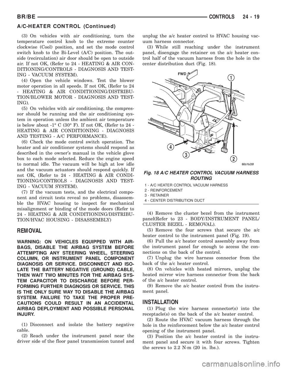
panel, disengage the retainer on the a/c heater con-
trol half of the vacuum harness from the hole in the
center distribution duct (Fig. 18).
(4) Remove the cluster bezel from the instrument
panel(Refer to 23 - BODY/INSTRUMENT PANEL/
CLUSTER BEZEL - REMOVAL).
(5) Remove the four screws that secure the a/c
heater control to the instrument panel (Fig. 19).
(6) Pull the a/c heater control assembly away from
the instrument panel far enough to access the con-
nections on the back of the control.
(7) Unplug the wire harness connector from the
back of the a/c heater control.
(8) On vehicles with heated mirrors, unplug the
heated mirror wire harness connector from the back
of the a/c heater control.
(9) Remove the a/c heater control from the instru-
ment panel.
INSTALLATION
(1) Plug the wire harness connector(s) into the
receptacle(s) on the back of the a/c heater control.
(2) Route the HVAC vacuum harness through the
hole in the reinforcement below the a/c heater control
opening of the instrument panel.
(3) Position the a/c heater control in the instru-
ment panel and secure it with four screws. Tighten
the screws to 2.2 N´m (20 in. lbs.).
Fig. 18 A/C HEATER CONTROL VACUUM HARNESS
ROUTING
1 - A/C HEATER CONTROL VACUUM HARNESS
2 - REINFORCEMENT
3 - RETAINER
4 - CENTER DISTRIBUTION DUCT
BR/BECONTROLS 24 - 19
A/C-HEATER CONTROL (Continued)
Page 2198 of 2255
The catalyst monitor uses dual oxygen sensors
(O2S's) to monitor the efficiency of the converter. The
dual O2S's sensor strategy is based on the fact that
as a catalyst deteriorates, its oxygen storage capacity
and its efficiency are both reduced. By monitoring
the oxygen storage capacity of a catalyst, its effi-
ciency can be indirectly calculated. The upstream
O2S is used to detect the amount of oxygen in the
exhaust gas before the gas enters the catalytic con-
verter. The PCM calculates the A/F mixture from the
output of the O2S. A low voltage indicates high oxy-
gen content (lean mixture). A high voltage indicates a
low content of oxygen (rich mixture).
When the upstream O2S detects a lean condition,
there is an abundance of oxygen in the exhaust gas.
A functioning converter would store this oxygen so it
can use it for the oxidation of HC and CO. As the
converter absorbs the oxygen, there will be a lack of
oxygen downstream of the converter. The output of
the downstream O2S will indicate limited activity in
this condition.
As the converter loses the ability to store oxygen,
the condition can be detected from the behavior of
the downstream O2S. When the efficiency drops, no
chemical reaction takes place. This means the con-
centration of oxygen will be the same downstream as
upstream. The output voltage of the downstream
O2S copies the voltage of the upstream sensor. The
only difference is a time lag (seen by the PCM)
between the switching of the O2S's.
To monitor the system, the number of lean-to-rich
switches of upstream and downstream O2S's is
counted. The ratio of downstream switches to
upstream switches is used to determine whether the
catalyst is operating properly. An effective catalyst
will have fewer downstream switches than it has
upstream switches i.e., a ratio closer to zero. For a
totally ineffective catalyst, this ratio will be one-to-
one, indicating that no oxidation occurs in the device.
The system must be monitored so that when cata-
lyst efficiency deteriorates and exhaust emissions
increase to over the legal limit, the MIL will be illu-
minated.
DESCRIPTION - TRIP DEFINITION
The term ªTripº has different meanings depending
on what the circumstances are. If the MIL (Malfunc-
tion Indicator Lamp) is OFF, a Trip is defined as
when the Oxygen Sensor Monitor and the Catalyst
Monitor have been completed in the same drive cycle.
When any Emission DTC is set, the MIL on the
dash is turned ON. When the MIL is ON, it takes 3
good trips to turn the MIL OFF. In this case, it
depends on what type of DTC is set to know what a
ªTripº is.For the Fuel Monitor or Mis-Fire Monitor (contin-
uous monitor), the vehicle must be operated in the
ªSimilar Condition Windowº for a specified amount of
time to be considered a Good Trip.
If a Non-Contiuous OBDII Monitor fails twice in a
row and turns ON the MIL, re-running that monitor
which previously failed, on the next start-up and
passing the monitor, is considered to be a Good Trip.
These will include the following:
²Oxygen Sensor
²Catalyst Monitor
²Purge Flow Monitor
²Leak Detection Pump Monitor (if equipped)
²EGR Monitor (if equipped)
²Oxygen Sensor Heater Monitor
If any other Emission DTC is set (not an OBDII
Monitor), a Good Trip is considered to be when the
Oxygen Sensor Monitor and Catalyst Monitor have
been completed; or 2 Minutes of engine run time if
the Oxygen Sensor Monitor or Catalyst Monitor have
been stopped from running.
It can take up to 2 Failures in a row to turn on the
MIL. After the MIL is ON, it takes 3 Good Trips to
turn the MIL OFF. After the MIL is OFF, the PCM
will self-erase the DTC after 40 Warm-up cycles. A
Warm-up cycle is counted when the ECT (Engine
Coolant Temperature Sensor) has crossed 160ÉF and
has risen by at least 40ÉF since the engine has been
started.
DESCRIPTION - COMPONENT MONITORS -
GAS ENGINES
There are several components that will affect vehi-
cle emissions if they malfunction. If one of these com-
ponents malfunctions the Malfunction Indicator
Lamp (MIL) will illuminate.
Some of the component monitors are checking for
proper operation of the part. Electrically operated
components now have input (rationality) and output
(functionality) checks. Previously, a component like
the Throttle Position sensor (TPS) was checked by
the PCM for an open or shorted circuit. If one of
these conditions occurred, a DTC was set. Now there
is a check to ensure that the component is working.
This is done by watching for a TPS indication of a
greater or lesser throttle opening than MAP and
engine rpm indicate. In the case of the TPS, if engine
vacuum is high and engine rpm is 1600 or greater,
and the TPS indicates a large throttle opening, a
DTC will be set. The same applies to low vacuum if
the TPS indicates a small throttle opening.
All open/short circuit checks, or any component
that has an associated limp-in, will set a fault after 1
trip with the malfunction present. Components with-
out an associated limp-in will take two trips to illu-
minate the MIL.
BR/BEEMISSIONS CONTROL 25 - 19
EMISSIONS CONTROL (Continued)