2002 DODGE RAM brake
[x] Cancel search: brakePage 123 of 2255
(3) Engine off, transmission in neutral, and park-
ing brake off.
(4) Remove wheel and bolt Special Tool 6790 or
equivalent tool to studs.
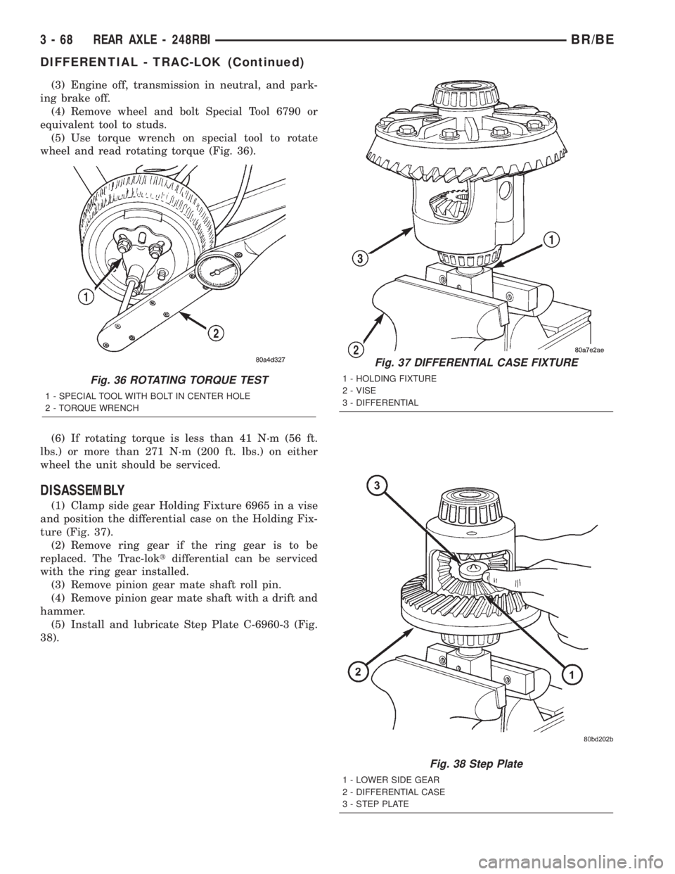
(5) Use torque wrench on special tool to rotate
wheel and read rotating torque (Fig. 36).
(6) If rotating torque is less than 41 N´m (56 ft.
lbs.) or more than 271 N´m (200 ft. lbs.) on either
wheel the unit should be serviced.
DISASSEMBLY
(1) Clamp side gear Holding Fixture 6965 in a vise
and position the differential case on the Holding Fix-
ture (Fig. 37).
(2) Remove ring gear if the ring gear is to be
replaced. The Trac-loktdifferential can be serviced
with the ring gear installed.
(3) Remove pinion gear mate shaft roll pin.
(4) Remove pinion gear mate shaft with a drift and
hammer.
(5) Install and lubricate Step Plate C-6960-3 (Fig.
38).
Fig. 36 ROTATING TORQUE TEST
1 - SPECIAL TOOL WITH BOLT IN CENTER HOLE
2 - TORQUE WRENCH
Fig. 37 DIFFERENTIAL CASE FIXTURE
1 - HOLDING FIXTURE
2 - VISE
3 - DIFFERENTIAL
Fig. 38 Step Plate
1 - LOWER SIDE GEAR
2 - DIFFERENTIAL CASE
3 - STEP PLATE
3 - 68 REAR AXLE - 248RBIBR/BE
DIFFERENTIAL - TRAC-LOK (Continued)
Page 137 of 2255

Condition Possible Causes Correction
Axle Overheating 1. Lubricant level low. 1. Fill differential to correct level.
2. Improper grade of lubricant. 2. Fill differential with the correct fluid
type and quantity.
3. Bearing pre-loads too high. 3. Re-adjust bearing pre-loads.
4. Insufficient ring gear backlash. 4. Re-adjust ring gear backlash.
Gear Teeth Broke 1. Overloading. 1. Replace gears. Examine other
gears and bearings for possible
damage.
2. Erratic clutch operation. 2. Replace gears and examine the
remaining parts for damage. Avoid
erratic clutch operation.
3. Ice-spotted pavement. 3. Replace gears and examine
remaining parts for damage.
4. Improper adjustments. 4. Replace gears and examine
remaining parts for damage. Ensure
ring gear backlash is correct.
Axle Noise 1. Insufficient lubricant. 1. Fill differential with the correct fluid
type and quantity.
2. Improper ring gear and pinion
adjustment.2. Check ring gear and pinion contact
pattern. Adjust backlash or pinion
depth.
3. Unmatched ring gear and pinion. 3. Replace gears with a matched ring
gear and pinion.
4. Worn teeth on ring gear and/or
pinion.4. Replace ring gear and pinion.
5. Loose pinion bearings. 5. Adjust pinion bearing pre-load.
6. Loose differential bearings. 6. Adjust differential bearing pre-load.
7. Mis-aligned or sprung ring gear. 7. Measure ring gear run-out.
Replace components as necessary.
8. Loose differential bearing cap
bolts.8. Inspect differential components
and replace as necessary. Ensure
that the bearing caps are torqued tot
he proper specification.
9. Housing not machined properly. 9. Replace housing.
REMOVAL
(1) Raise and support the vehicle.
(2) Position an axle lift under the axle and secure
it to the axle.
(3) Remove the wheels and tires.
(4) Remove RWAL sensor from the differential
housing, if necessary.
(5) Remove brake hose from the axle junction
block.
(6) Disconnect parking brake cables and cable
brackets.
(7) Remove vent hose from the axle shaft tube.(8) Mark propeller shaft and yoke for installation
alignment reference.
(9) Remove propeller shaft.
(10) Remove shock absorbers from the axle brack-
ets.
(11) Remove spring clamps and spring brackets.
(12) Remove axle from the vehicle.
INSTALLATION
(1) Raise axle with lift and align to the leaf spring
centering bolts.
(2) Install spring clamps and spring brackets.
3 - 82 REAR AXLE - 267RBIBR/BE
REAR AXLE - 267RBI (Continued)
Page 138 of 2255

(3) Install shock absorbers and tighten to specifica-
tions.
(4) Install RWAL sensor to the differential hous-
ing, if necessary.
(5) Install parking brake cables and cable brackets
(6) Install brake hose to the axle junction block.
(7) Install axle vent hose.
(8) Install propeller shaft with reference marks
aligned.
(9) Install wheels and tires assemblies.
(10) Add gear lubricant, if necessary.
(11) Remove lift from the axle and lower the vehi-
cle.
ADJUSTMENTS
Ring and pinion gears are supplied as matched
sets only. The identifying numbers for the ring and
pinion gear are etched onto each gear (Fig. 4). A plus
(+) number, minus (±) number or zero (0) is etched
onto the pinion gear. This number is the amount (in
thousandths of an inch) the depth varies from the
standard depth setting of a pinion etched with a (0).
The standard setting from the center line of the ring
gear to the back face of the pinion is 136.53 mm
(5.375 in.). The standard depth provides the best
gear tooth contact pattern. Refer to Backlash and
Contact Pattern in this section for additional infor-
mation.
Compensation for pinion depth variance is
achieved with a select shim/oil baffle. The shims are
placed between the rear pinion bearing and the pin-
ion gear head (Fig. 5).
If a new gear set is being installed, note the depth
variance etched into both the original and replace-
ment pinion. Add or subtract this number from the
thickness of the original depth shim/oil slinger to
compensate for the difference in the depth variances.
Refer to the Depth Variance chart.
Note where Old and New Pinion Marking columns
intersect. Intersecting figure represents plus or
minus the amount needed.
Note the etched number on the face of the pinion
gear head (±1, ±2, 0, +1, +2, etc.). The numbers rep-
resent thousands of an inch deviation from the stan-
dard. If the number is negative, add that value to the
required thickness of the depth shims. If the number
is positive, subtract that value from the thickness of
the depth shim. If the number is 0 no change is nec-
essary.Fig. 4 PINION GEAR ID NUMBERS
1 - PRODUCTION NUMBERS
2 - PINION GEAR DEPTH VARIANCE
3 - GEAR MATCHING NUMBER
Fig. 5 SHIM LOCATIONS
1 - PINION GEAR DEPTH SHIM/OIL BAFFLE
2 - DIFFERENTIAL BEARING SHIM
BR/BEREAR AXLE - 267RBI 3 - 83
REAR AXLE - 267RBI (Continued)
Page 149 of 2255
AXLE SHAFTS
REMOVAL
(1) Remove the axle shaft flange bolts.
(2) Slide the axle shaft out from the axle tube.
INSTALLATION
(1) Clean the gasket contact surface area on the
flange with an appropriate solvent. Install a new
flange gasket and slide the axle shaft into the tube.
(2) Install the bolts and tighten to 129 N´m (95 ft.
lbs.).
AXLE BEARINGS
REMOVAL
(1) Remove wheel and tire assembly.
(2) Remove brake drum.
(3) Remove the axle shaft.
(4) Remove the lock wedge and adjustment nut.
Use Socket DD-1241±JD to remove the adjustment
nut.
(5) Remove the hub assembly. The outer axle bear-
ing will slide out as the hub is being removed.
(6) Remove inner grease seal and discard. Use
Installer 5064 and Handle C-4171 to drive grease
seal and inner axle bearing from the hub.
(7) Remove the bearing cups from the hub bore.
Use a brass drift, or an appropriate removal tool, to
tap out the cups.
INSTALLATION
(1) Thoroughly clean both axle bearings and inte-
rior of the hub with an appropriate cleaning solvent.
(2) Install bearing cups with Installer 8151 and
Handle C-4171.
(3)Pack inner and outer bearings with
Mopar wheel bearing grease or equivalent.
(4) Apply grease to inner and outer bearing cup
surfaces.
(5) Install inner axle bearing in the hub.
(6) Installnewgrease seal in hub with Installer
8149 and Handle C-4171.
(7) Inspect bearing and seal contact surfaces on
the axle tube for burrs/roughness. Remove all the
rough contact surfaces from the axle tube.
(8) Carefully slide the hub onto the axle.
CAUTION: Do not let grease seal contact axle tube
threads during installtion.
(9) Install outer axle bearing.
(10) Install hub bearing adjustment nut with
Socket DD-1241±JD.(11) Tighten adjustment nut to 163-190 N´m (120-
140 ft. lbs.) while rotating the wheel. Then loosen
adjustment nut 1/8 to 1/3 of-a-turn to provide 0.025-
0.250mm (0.001-0.009 in.) wheel bearing end play.
(12) Tap locking wedge into the spindle keyway
and adjustment nut.
NOTE: Located locking wedge in a new position in
the adjustment nut.
(13) Install axle shaft and brake drum.
(14) Install the wheel and tire assembly.
PINION SEAL
REMOVAL
(1) Raise and support the vehicle.
(2) Mark universal joint, pinion yoke and shaft for
installation reference.
(3) Disconnect the propeller shaft from the pinion
yoke.
(4) Remove the wheel and tire assemblies.
(5) Remove brake calipers to prevent any drag
that may cause a false bearing preload torque mea-
surement.
(6) Rotate pinion yoke three or four times.
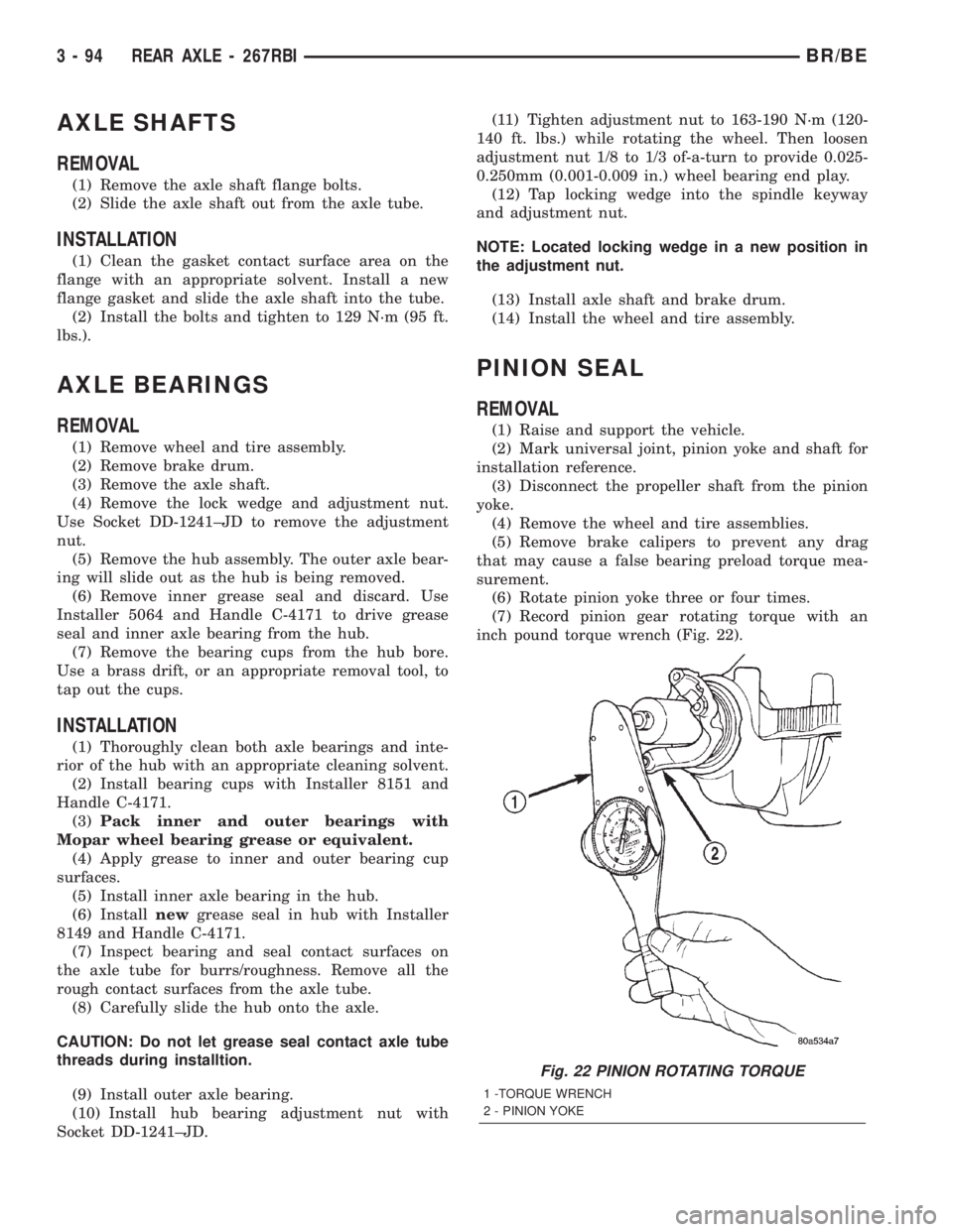
(7) Record pinion gear rotating torque with an
inch pound torque wrench (Fig. 22).
Fig. 22 PINION ROTATING TORQUE
1 -TORQUE WRENCH
2 - PINION YOKE
3 - 94 REAR AXLE - 267RBIBR/BE
Page 150 of 2255
(8) Hold yoke with Yoke Holder 6719A and remove
the pinion shaft nut and washer.
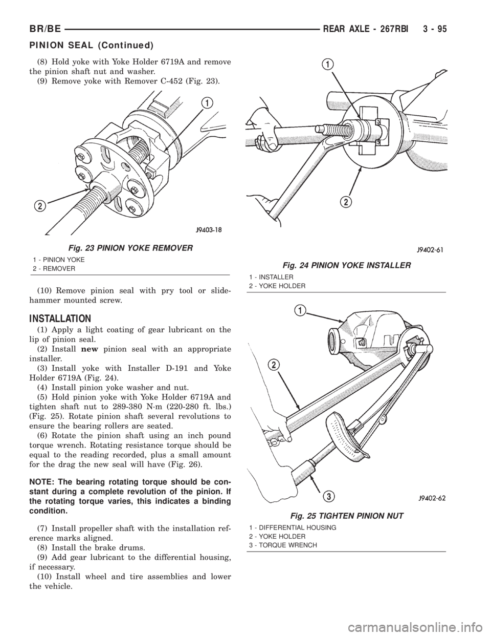
(9) Remove yoke with Remover C-452 (Fig. 23).
(10) Remove pinion seal with pry tool or slide-
hammer mounted screw.
INSTALLATION
(1) Apply a light coating of gear lubricant on the
lip of pinion seal.
(2) Installnewpinion seal with an appropriate
installer.
(3) Install yoke with Installer D-191 and Yoke
Holder 6719A (Fig. 24).
(4) Install pinion yoke washer and nut.
(5) Hold pinion yoke with Yoke Holder 6719A and
tighten shaft nut to 289-380 N´m (220-280 ft. lbs.)
(Fig. 25). Rotate pinion shaft several revolutions to
ensure the bearing rollers are seated.
(6) Rotate the pinion shaft using an inch pound
torque wrench. Rotating resistance torque should be
equal to the reading recorded, plus a small amount
for the drag the new seal will have (Fig. 26).
NOTE: The bearing rotating torque should be con-
stant during a complete revolution of the pinion. If
the rotating torque varies, this indicates a binding
condition.
(7) Install propeller shaft with the installation ref-
erence marks aligned.
(8) Install the brake drums.
(9) Add gear lubricant to the differential housing,
if necessary.
(10) Install wheel and tire assemblies and lower
the vehicle.
Fig. 23 PINION YOKE REMOVER
1 - PINION YOKE
2 - REMOVERFig. 24 PINION YOKE INSTALLER
1 - INSTALLER
2 - YOKE HOLDER
Fig. 25 TIGHTEN PINION NUT
1 - DIFFERENTIAL HOUSING
2 - YOKE HOLDER
3 - TORQUE WRENCH
BR/BEREAR AXLE - 267RBI 3 - 95
PINION SEAL (Continued)
Page 154 of 2255
(13) Install the fill hole plug and tighten to 34 N´m
(25 ft. lbs.).
(14) Remove support and lower vehicle.
DIFFERENTIAL - POWR-LOK
DIAGNOSIS AND TESTING - POWR-LOKT
WARNING: WHEN SERVICING VEHICLES WITH A
POWR-LOKTDIFFERENTIAL DO NOT USE THE
ENGINE TO TURN THE AXLE AND WHEELS. BOTH
REAR WHEELS MUST BE RAISED AND THE VEHI-
CLE SUPPORTED. THE AXLE CAN EXERT ENOUGH
FORCE IF ONE WHEEL IS IN CONTACT WITH A
SURFACE TO CAUSE THE VEHICLE TO MOVE.
The differential can be tested without removing the
differential case by measuring rotating torque. Make
sure brakes are not dragging during this measure-
ment.
(1) Place blocks in front and rear of both front
wheels.
(2) Raise one rear wheel until it is completely off
the ground.
(3) Engine off, transmission in neutral, and park-
ing brake off.
(4) Remove wheel and bolt Special Tool 6790 or
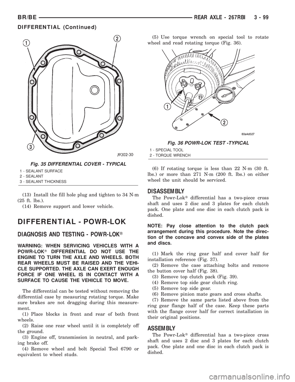
equivalent to wheel studs.(5) Use torque wrench on special tool to rotate
wheel and read rotating torque (Fig. 36).
(6) If rotating torque is less than 22 N´m (30 ft.
lbs.) or more than 271 N´m (200 ft. lbs.) on either
wheel the unit should be serviced.
DISASSEMBLY
The Powr-Loktdifferential has a two-piece cross
shaft and uses 2 disc and 3 plates for each clutch
pack. One plate and one disc in each clutch pack is
dished.
NOTE: Pay close attention to the clutch pack
arrangement during this procedure. Note the direc-
tion of the concave and convex side of the plates
and discs.
(1) Mark the ring gear half and cover half for
installation reference (Fig. 37).
(2) Remove the case attaching bolts and remove
the button cover half (Fig. 38).
(3) Remove top clutch pack (Fig. 39).
(4) Remove top side gear clutch ring.
(5) Remove top side gear.
(6) Remove pinion mate gears and cross shafts.
(7) Remove the same parts listed above from the
ring gear flange half of the case. Keep these parts
with the flange cover half for correct installation in
their original positions.
ASSEMBLY
The Powr-Loktdifferential has a two-piece cross
shaft and uses 2 disc and 3 plates for each clutch
pack. One plate and one disc in each clutch pack is
dished.
Fig. 35 DIFFERENTIAL COVER - TYPICAL
1 - SEALANT SURFACE
2 - SEALANT
3 - SEALANT THICKNESS
Fig. 36 POWR-LOK TEST -TYPICAL
1 - SPECIAL TOOL
2 - TORQUE WRENCH
BR/BEREAR AXLE - 267RBI 3 - 99
DIFFERENTIAL (Continued)
Page 167 of 2255

REMOVAL
(1) Raise and support the vehicle.
(2) Position a suitable lifting device under the
axle.
(3) Secure axle to device.
(4) Remove the wheels and tires.
(5) Remove the RWAL sensor from the differential
housing, if necessary.
(6) Disconnect the brake hose at the axle junction
block.
(7) Disconnect the parking brake cables and cable
brackets.
(8)
Disconnect the vent hose from the axle shaft tube.
(9) Mark the propeller shaft and companion flange
for installation alignment reference.
(10) Remove propeller shaft.
(11) Disconnect shock absorbers from axle.
(12)
Remove the spring clamps and spring brackets.
(13) Separate the axle from the vehicle.
INSTALLATION
(1) Raise the axle with lifting device and align to
the leaf spring centering bolts.
(2) Install the spring clamps and spring brackets.
(3) Install the shock absorbers.
(4) Install the RWAL sensor to the differential
housing, if necessary
(5) Install the parking brake cables and cable
brackets.
(6)
Install the brake hose to the axle junction block.
(7) Install axle vent hose.
(8) Install the propeller shaft with reference marks
aligned.
(9) Install the wheels and tires.
(10) Add gear lubricant, if necessary. Refer to
Specifications for lubricant requirements.
(11) Remove lifting device from axle and lower the
vehicle.
ADJUSTMENTS
Ring and pinion gears are supplied as matched
sets only. The identifying numbers for the ring and
pinion gear are etched into the face of each gear (Fig.
4). A plus (+) number, minus (±) number or zero (0) is
etched into the face of the pinion gear. This number
is the amount (in thousandths of an inch) the depth
varies from the standard depth setting of a pinion
etched with a (0). The standard setting from the cen-
ter line of the ring gear to the back face of the pinion
is 147.625 mm (5.812 in.). The standard depth pro-
vides the best teeth contact pattern. Refer to Back-
lash and Contact Pattern Analysis Paragraph in this
section for additional information.
Compensation for pinion depth variance is
achieved with select shims. The shims are placed
under the inner pinion bearing cone (Fig. 5).If a new gear set is being installed, note the depth
variance etched into both the original and replace-
ment pinion gear. Add or subtract the thickness of
the original depth shims to compensate for the differ-
ence in the depth variances. Refer to the Depth Vari-
ance charts.
Note where Old and New Pinion Marking columns
intersect. Intersecting figure represents plus or
minus amount needed.
Note the etched number on the face of the drive pin-
ion gear (±1, ±2, 0, +1, +2, etc.). The numbers represent
Fig. 4 PINION GEAR ID NUMBERS
1 - PRODUCTION NUMBERS
2 - PINION GEAR DEPTH VARIANCE
3 - GEAR MATCHING NUMBER
Fig. 5 SHIM LOCATIONS
1 - PINION BEARING PRELOAD SHIM
2 - DIFFERENTIAL BEARING SHIM
3 - PINION GEAR DEPTH SHIM
3 - 112 REAR AXLE - 286RBIBR/BE
REAR AXLE - 286RBI (Continued)
Page 178 of 2255
AXLE SHAFTS
REMOVAL
(1) Remove the axle shaft flange bolts.
(2) Slide the axle shaft out from the axle tube.
INSTALLATION
(1) Clean the gasket contact surface area on the
flange with an appropriate solvent. Install a new
flange gasket and slide the axle shaft into the tube.
(2) Install the bolts and tighten to 129 N´m (95 ft.
lbs.).
AXLE BEARINGS
REMOVAL
(1) Remove wheel and tire assembly.
(2) Remove brake drum.
(3) Remove the axle shaft.
(4) Remove the lock wedge and adjustment nut.
Remove adjustment nut with Socket DD-1241-JD.
(5) Remove the hub assembly. The outer axle bear-
ing will slide out as the hub is being removed.
(6) Drive grease seal and inner bearing out of the
hub with Installer 5064 and Handle C-4171.
(7) Remove bearing cups from the hub with a
brass drift and a hammer.
INSTALLATION
(1) Thoroughly clean both axle bearings and inte-
rior of the hub with an appropriate cleaning solvent.
(2) Install bearing cups with Installer 8153 and
Handle C-4171.
(3) Pack inner and outer bearings with Mopar
wheel bearing grease or equivalent
(4) Apply lubricant to surface area of the bearing
cup.
(5) Install inner axle bearing in the hub.
(6) Install anewbearing grease seal with
Installer 8152 and Handle C-4171.
(7) Inspect bearing and seal contact surfaces on
the axle tube spindle for burrs and/or roughness.
Remove all the rough contact surfaces from the axle
spindle.
CAUTION: Do not let grease seal contact the axle
tube threads during installation.
(8) Carefully slide the hub onto the axle.
(9) Install outer axle bearing.
(10) Install hub bearing adjustment nut with
Socket DD-1241±JD.
(11) Tighten adjustment nut to 163-190 N´m (120-
140 ft. lbs.) while rotating the wheel.(12) Loosen adjustment nut 1/8 of-a-turn to pro-
vide 0.001-inch to 0.010-inch wheel bearing end play.
(13) Tap the locking wedge into the spindle key-
way and adjustment nut.
NOTE: Locate locking wedge in a new position in
the adjustment nut.
(14) Install axle shaft and brake drum.
(15) Install wheel and tire assembly.
PINION SEAL
REMOVAL
(1) Raise and support the vehicle.
(2) Mark the universal joint, pinion yoke, and pin-
ion shaft for installation reference.
(3) Disconnect the propeller shaft from the pinion
yoke. Secure the propeller shaft in an upright posi-
tion to prevent damage to the rear universal joint.
(4) Remove wheel and tire assemblies.
(5) Remove brake calipers to prevent any drag.
The drag may cause a false bearing preload torque
measurement.
(6) Rotate pinion yoke three or four times.
(7) Record the amount of torque necessary to
rotate the pinion gear with an inch pound dial-type
torque wrench.
(8) Hold the yoke with Holder 6719A and remove
the pinion shaft nut and washer.
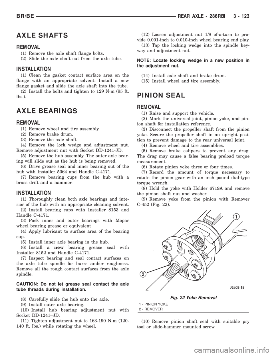
(9) Remove yoke from the pinion with Remover
C-452 (Fig. 22).
(10) Remove pinion shaft seal with suitable pry
tool or slide-hammer mounted screw.
Fig. 22 Yoke Removal
1 - PINION YOKE
2 - REMOVER
BR/BEREAR AXLE - 286RBI 3 - 123