2002 DODGE RAM airbag disable
[x] Cancel search: airbag disablePage 523 of 2255
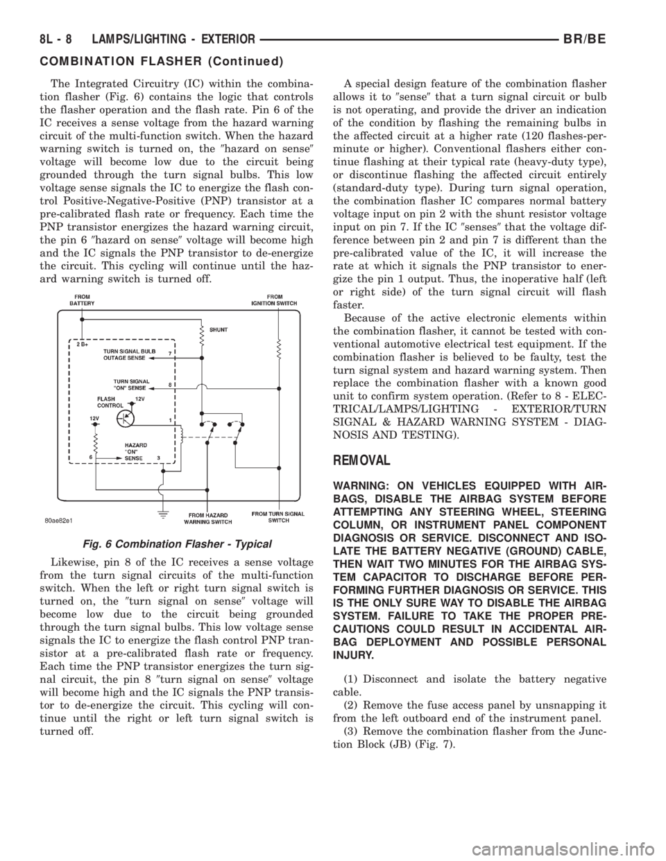
The Integrated Circuitry (IC) within the combina-
tion flasher (Fig. 6) contains the logic that controls
the flasher operation and the flash rate. Pin 6 of the
IC receives a sense voltage from the hazard warning
circuit of the multi-function switch. When the hazard
warning switch is turned on, the9hazard on sense9
voltage will become low due to the circuit being
grounded through the turn signal bulbs. This low
voltage sense signals the IC to energize the flash con-
trol Positive-Negative-Positive (PNP) transistor at a
pre-calibrated flash rate or frequency. Each time the
PNP transistor energizes the hazard warning circuit,
the pin 69hazard on sense9voltage will become high
and the IC signals the PNP transistor to de-energize
the circuit. This cycling will continue until the haz-
ard warning switch is turned off.
Likewise, pin 8 of the IC receives a sense voltage
from the turn signal circuits of the multi-function
switch. When the left or right turn signal switch is
turned on, the9turn signal on sense9voltage will
become low due to the circuit being grounded
through the turn signal bulbs. This low voltage sense
signals the IC to energize the flash control PNP tran-
sistor at a pre-calibrated flash rate or frequency.
Each time the PNP transistor energizes the turn sig-
nal circuit, the pin 89turn signal on sense9voltage
will become high and the IC signals the PNP transis-
tor to de-energize the circuit. This cycling will con-
tinue until the right or left turn signal switch is
turned off.A special design feature of the combination flasher
allows it to9sense9that a turn signal circuit or bulb
is not operating, and provide the driver an indication
of the condition by flashing the remaining bulbs in
the affected circuit at a higher rate (120 flashes-per-
minute or higher). Conventional flashers either con-
tinue flashing at their typical rate (heavy-duty type),
or discontinue flashing the affected circuit entirely
(standard-duty type). During turn signal operation,
the combination flasher IC compares normal battery
voltage input on pin 2 with the shunt resistor voltage
input on pin 7. If the IC9senses9that the voltage dif-
ference between pin 2 and pin 7 is different than the
pre-calibrated value of the IC, it will increase the
rate at which it signals the PNP transistor to ener-
gize the pin 1 output. Thus, the inoperative half (left
or right side) of the turn signal circuit will flash
faster.
Because of the active electronic elements within
the combination flasher, it cannot be tested with con-
ventional automotive electrical test equipment. If the
combination flasher is believed to be faulty, test the
turn signal system and hazard warning system. Then
replace the combination flasher with a known good
unit to confirm system operation. (Refer to 8 - ELEC-
TRICAL/LAMPS/LIGHTING - EXTERIOR/TURN
SIGNAL & HAZARD WARNING SYSTEM - DIAG-
NOSIS AND TESTING).
REMOVAL
WARNING: ON VEHICLES EQUIPPED WITH AIR-
BAGS, DISABLE THE AIRBAG SYSTEM BEFORE
ATTEMPTING ANY STEERING WHEEL, STEERING
COLUMN, OR INSTRUMENT PANEL COMPONENT
DIAGNOSIS OR SERVICE. DISCONNECT AND ISO-
LATE THE BATTERY NEGATIVE (GROUND) CABLE,
THEN WAIT TWO MINUTES FOR THE AIRBAG SYS-
TEM CAPACITOR TO DISCHARGE BEFORE PER-
FORMING FURTHER DIAGNOSIS OR SERVICE. THIS
IS THE ONLY SURE WAY TO DISABLE THE AIRBAG
SYSTEM. FAILURE TO TAKE THE PROPER PRE-
CAUTIONS COULD RESULT IN ACCIDENTAL AIR-
BAG DEPLOYMENT AND POSSIBLE PERSONAL
INJURY.
(1) Disconnect and isolate the battery negative
cable.
(2) Remove the fuse access panel by unsnapping it
from the left outboard end of the instrument panel.
(3) Remove the combination flasher from the Junc-
tion Block (JB) (Fig. 7).
Fig. 6 Combination Flasher - Typical
8L - 8 LAMPS/LIGHTING - EXTERIORBR/BE
COMBINATION FLASHER (Continued)
Page 524 of 2255

INSTALLATION
WARNING: ON VEHICLES EQUIPPED WITH AIR-
BAGS, DISABLE THE AIRBAG SYSTEM BEFORE
ATTEMPTING ANY STEERING WHEEL, STEERING
COLUMN, OR INSTRUMENT PANEL COMPONENT
DIAGNOSIS OR SERVICE. DISCONNECT AND ISO-
LATE THE BATTERY NEGATIVE (GROUND) CABLE,
THEN WAIT TWO MINUTES FOR THE AIRBAG SYS-
TEM CAPACITOR TO DISCHARGE BEFORE PER-
FORMING FURTHER DIAGNOSIS OR SERVICE. THIS
IS THE ONLY SURE WAY TO DISABLE THE AIRBAG
SYSTEM. FAILURE TO TAKE THE PROPER PRE-
CAUTIONS COULD RESULT IN ACCIDENTAL AIR-
BAG DEPLOYMENT AND POSSIBLE PERSONAL
INJURY.
(1) Position the combination flasher in the proper
receptacle of the Junction Block (JB).
(2) Align the terminals of the combination flasher
with the terminal cavities in the JB receptacle for
the flasher.
(3) Push in firmly and evenly on the combination
flasher until the terminals are fully seated in the ter-
minal cavities of the JB receptacle for the flasher.
(4) Reinstall the fuse access panel by snapping it
onto the left outboard end of the instrument panel.
(5) Reconnect the battery negative cable.
DAYTIME RUNNING LAMP
MODULE
DESCRIPTION
The Daytime Running Lights (Headlamps) System
is installed on vehicles manufactured for sale in Can-
ada only. A separate module, mounted on the cowl,
controls the DRL.
OPERATION
The headlamps are illuminated when the ignition
switch is turned to the ON position. The DRL module
receives a vehicle-moving signal from the vehicle
speed sensor. This provides a constanthead-
lamps-oncondition as long as the vehicle is moving.
The lamps are illuminated at less than 50 percent of
normal intensity.
REMOVAL
(1) Disconnect and isolate the battery negative
cable.
(2) Disengage wire connector from DRLM (Fig. 8).
(3) Remove screws attaching DRLM to left front
inner fender panel.
(4) Separate DRLM from fender.
INSTALLATION
(1) Position DRLM on fender.
(2) Install screws attaching DRLM to left front
inner fender panel.
(3) Engage wire connector to DRLM.
(4) Connect the battery negative cable.
Fig. 7 Junction Block
1 - JUNCTION BLOCK
2 - FUSE ACCESS PANEL
Fig. 8 Daytime Running Lamp Module (DRLM)
1 - HEADLAMP AND DASH WIRING HARNESS
2 - LEFT FENDER SIDE SHIELD
3 - DAYTIME RUNNING LAMP MODULE
BR/BELAMPS/LIGHTING - EXTERIOR 8L - 9
COMBINATION FLASHER (Continued)
Page 534 of 2255
DIAGNOSIS AND TESTING - HEADLAMP
SWITCH
For circuit descriptions and diagrams, refer to the
appropriate wiring information. The wiring informa-
tion includes wiring diagrams, proper wire and con-
nector repair procedures, details of wire harness
routing and retention, connector pin-out information
and location views for the various wire harness con-
nectors, splices and grounds.
WARNING: ON VEHICLES EQUIPPED WITH AIR-
BAGS, REFER TO ELECTRICAL, RESTRAINTS
BEFORE ATTEMPTING ANY STEERING WHEEL,
STEERING COLUMN, OR INSTRUMENT PANEL
COMPONENT DIAGNOSIS OR SERVICE. FAILURE
TO TAKE THE PROPER PRECAUTIONS COULD
RESULT IN ACCIDENTAL AIRBAG DEPLOYMENT
AND POSSIBLE PERSONAL INJURY.
(1) Disconnect and isolate the battery negative
cable. Remove the headlamp switch from the instru-
ment panel. (Refer to 8 - ELECTRICAL/LAMPS/
LIGHTING - EXTERIOR/HEADLAMP SWITCH -
REMOVAL) for the procedures. Unplug the headlamp
switch wire harness connectors. Check for continuity
between the left door jamb switch sense circuit cavity
of the headlamp switch wire harness connector and a
good ground. There should be continuity with the
driver door open, and no continuity with the driver
door closed. If OK, go to Step 2. If not OK, repair the
circuit to the driver door jamb switch as required.
(2) Remove the Central Timer Module (CTM) from
its mounting bracket to access the CTM wire harness
connectors. (Refer to 8 - ELECTRICAL/ELEC-
TRONIC CONTROL MODULES/BODY CONTROL/
CENTRAL TIMER MODUL - REMOVAL) for the
procedures. Unplug the 14-way CTM wire harness
connector. Remove the key from the ignition lock cyl-
inder. Check for continuity between the key-in igni-
tion switch sense circuit cavity of the 14-way CTM
wire harness connector and a good ground. There
should be no continuity. If OK, go to Step 3. If not
OK, repair the short circuit as required.
(3) Check for continuity between the key-in igni-
tion switch sense circuit cavities of the 14-way CTM
wire harness connector and the headlamp switch
wire harness connector. There should be continuity. If
OK, go to Step 4. If not OK, repair the open circuit
as required.
(4) Check for continuity between the left front door
jamb switch sense circuit terminal and the key-in
ignition switch sense circuit terminal of the head-
lamp switch. There should be no continuity with the
switch in the Off position, and continuity with the
switch in the park or head lamps On position. If
OK,(Refer to 8 - ELECTRICAL/ELECTRONIC CON-TROL MODULES/BODY CONTROL/CENTRAL
TIMER MODUL - DIAGNOSIS AND TESTING) If
not OK, replace the faulty headlamp switch.
REMOVAL
WARNING: ON VEHICLES EQUIPPED WITH AIR-
BAGS, DISABLE THE AIRBAG SYSTEM BEFORE
ATTEMPTING ANY STEERING WHEEL, STEERING
COLUMN, OR INSTRUMENT PANEL COMPONENT
DIAGNOSIS OR SERVICE. DISCONNECT AND ISO-
LATE THE BATTERY NEGATIVE (GROUND) CABLE,
THEN WAIT TWO MINUTES FOR THE AIRBAG SYS-
TEM CAPACITOR TO DISCHARGE BEFORE PER-
FORMING FURTHER DIAGNOSIS OR SERVICE. THIS
IS THE ONLY SURE WAY TO DISABLE THE AIRBAG
SYSTEM. FAILURE TO TAKE THE PROPER PRE-
CAUTIONS COULD RESULT IN ACCIDENTAL AIR-
BAG DEPLOYMENT AND POSSIBLE PERSONAL
INJURY.
(1) Disconnect and isolate the battery negative
cable.
(2) Remove the cluster bezel from the instrument
panel. (Refer to 23 - BODY/INSTRUMENT PANEL/
CLUSTER BEZEL - REMOVAL).
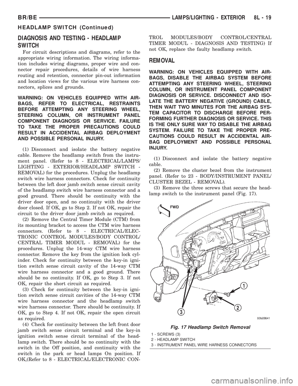
(3) Remove the three screws that secure the head-
lamp switch to the instrument panel (Fig. 17).
Fig. 17 Headlamp Switch Removal
1 - SCREWS (3)
2 - HEADLAMP SWITCH
3 - INSTRUMENT PANEL WIRE HARNESS CONNECTORS
BR/BELAMPS/LIGHTING - EXTERIOR 8L - 19
HEADLAMP SWITCH (Continued)
Page 535 of 2255
(4) Pull the headlamp switch away from the
instrument panel far enough to access the instru-
ment panel wire harness connectors.
(5) Disconnect the two instrument panel wire har-
ness connectors for the headlamp switch from the
connector receptacles on the back of the switch.
(6) Remove the headlamp switch from the instru-
ment panel.
INSTALLATION
WARNING: ON VEHICLES EQUIPPED WITH AIR-
BAGS, DISABLE THE AIRBAG SYSTEM BEFORE
ATTEMPTING ANY STEERING WHEEL, STEERING
COLUMN, OR INSTRUMENT PANEL COMPONENT
DIAGNOSIS OR SERVICE. DISCONNECT AND ISO-
LATE THE BATTERY NEGATIVE (GROUND) CABLE,
THEN WAIT TWO MINUTES FOR THE AIRBAG SYS-
TEM CAPACITOR TO DISCHARGE BEFORE PER-
FORMING FURTHER DIAGNOSIS OR SERVICE. THIS
IS THE ONLY SURE WAY TO DISABLE THE AIRBAG
SYSTEM. FAILURE TO TAKE THE PROPER PRE-
CAUTIONS COULD RESULT IN ACCIDENTAL AIR-
BAG DEPLOYMENT AND POSSIBLE PERSONAL
INJURY.
(1) Position the headlamp switch to the instru-
ment panel.
(2) Reconnect the two instrument panel wire har-
ness connectors for the headlamp switch to the con-
nector receptacles on the back of the switch.
(3) Position the headlamp switch into the instru-
ment panel.
(4) Install and tighten the three screws that secure
the headlamp switch to the instrument panel.
Tighten the screws to 2.2 N´m (20 in. lbs.).
(5) Reinstall the cluster bezel onto the instrument
panel. (Refer to 23 - BODY/INSTRUMENT PANEL/
CLUSTER BEZEL - INSTALLATION).
(6) Connect the battery negative cable.
HEADLAMP UNIT
REMOVAL
(1) Disconnect and isolate the battery negative
cable.
(2) Remove push-in fastener attaching seal to radi-
ator closure panel.
(3) Remove park and turn signal lamp.
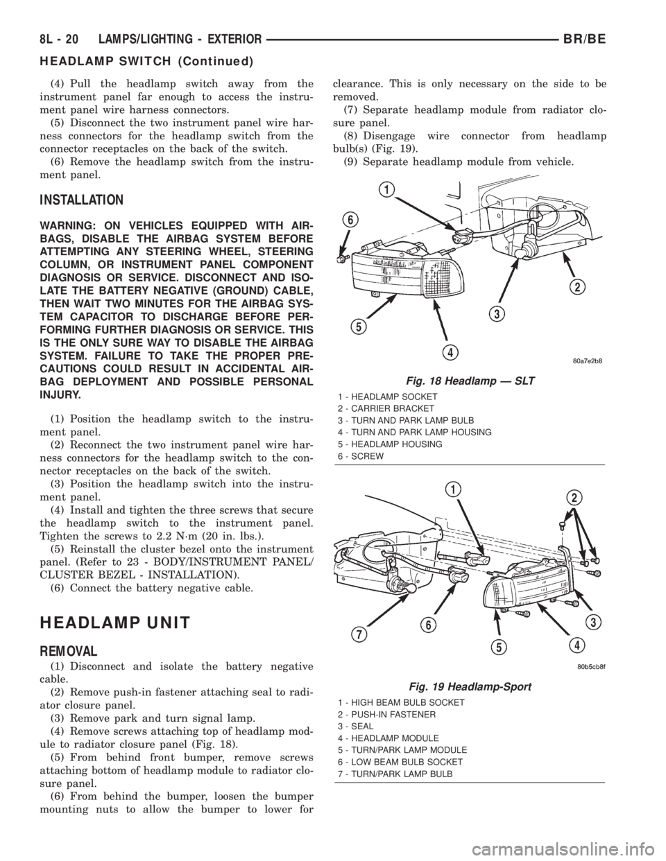
(4) Remove screws attaching top of headlamp mod-
ule to radiator closure panel (Fig. 18).
(5) From behind front bumper, remove screws
attaching bottom of headlamp module to radiator clo-
sure panel.
(6) From behind the bumper, loosen the bumper
mounting nuts to allow the bumper to lower forclearance. This is only necessary on the side to be
removed.
(7) Separate headlamp module from radiator clo-
sure panel.
(8) Disengage wire connector from headlamp
bulb(s) (Fig. 19).
(9) Separate headlamp module from vehicle.
Fig. 18 Headlamp Ð SLT
1 - HEADLAMP SOCKET
2 - CARRIER BRACKET
3 - TURN AND PARK LAMP BULB
4 - TURN AND PARK LAMP HOUSING
5 - HEADLAMP HOUSING
6 - SCREW
Fig. 19 Headlamp-Sport
1 - HIGH BEAM BULB SOCKET
2 - PUSH-IN FASTENER
3 - SEAL
4 - HEADLAMP MODULE
5 - TURN/PARK LAMP MODULE
6 - LOW BEAM BULB SOCKET
7 - TURN/PARK LAMP BULB
8L - 20 LAMPS/LIGHTING - EXTERIORBR/BE
HEADLAMP SWITCH (Continued)
Page 540 of 2255
²Turn Signal Control- The multi-function
switch control stalk actuates the turn signal switch.
When the control stalk is moved in the upward direc-
tion, the right turn signal circuitry is activated; and,
when the control stalk is moved in the downward
direction, the left turn signal circuitry is activated.
The multi-function switch turn signal circuitry simul-
taneously provides a signal to the turn signal sense
of the combination flasher to activate or deactivate
the flasher output, and directs the output of the
flasher to the proper turn signal lamps. The turn sig-
nal switch has a detent position in each direction
that provides turn signals with automatic cancella-
tion, and an intermediate, momentary position in
each direction that provides turn signals only until
the multi-function switch control stalk is released.
When the control stalk is moved to a turn signal
switch detent position, the cancel actuator extends
toward the center of the steering column. A turn sig-
nal cancel cam that is integral to the clockspring
mechanism rotates with the steering wheel and the
cam lobes contact the cancel actuator when it is
extended from the multi-function switch. When the
steering wheel is rotated during a turning maneuver,
one of the two turn signal cancel cam lobes will con-
tact the turn signal cancel actuator. The cancel
actuator latches against the cancel cam rotation in
the direction opposite that which is signaled. In other
words, if the left turn signal detent is selected, the
lobes of the cancel cam will ratchet past the cancel
actuator when the steering wheel is rotated to the
left, but will unlatch the cancel actuator as the steer-
ing wheel rotates to the right and returns to center,
which will cancel the turn signal event and release
the control stalk from the detent so it returns to the
neutral Off position.
²Washer Mode- Pushing the button on the end
of the multi-function switch control knob towards the
steering column provides a battery current output
through the momentary single pole, single throw
washer switch circuitry to operate the washer pump/
motor and provides a signal to the CTM. If the wip-
ers are not operating when the washer switch is
actuated, the CTM will operate the wiper motor for
as long as the washer switch is depressed plus about
three additional wipe cycles. If the wipers are oper-
ating in the intermittent mode when the washer
switch is actuated, the CTM will operate the wiper
motor at a fixed low speed for as long as the washer
switch is depressed plus about three additional wipe
cycles before the wipers return to the selected inter-
mittent wipe interval.DIAGNOSIS AND TESTING - MULTI-FUNCTION
SWITCH
Refer to the appropriate wiring information. The
wiring information includes wiring diagrams, proper
wire and connector repair procedures, details of wire
harness routing and retention, connector pin-out
information and location views for the various wire
harness connectors, splices and grounds.
WARNING: ON VEHICLES EQUIPPED WITH AIR-
BAGS, DISABLE THE AIRBAG SYSTEM BEFORE
ATTEMPTING ANY STEERING WHEEL, STEERING
COLUMN, OR INSTRUMENT PANEL COMPONENT
DIAGNOSIS OR SERVICE. DISCONNECT AND ISO-
LATE THE BATTERY NEGATIVE (GROUND) CABLE,
THEN WAIT TWO MINUTES FOR THE AIRBAG SYS-
TEM CAPACITOR TO DISCHARGE BEFORE PER-
FORMING FURTHER DIAGNOSIS OR SERVICE. THIS
IS THE ONLY SURE WAY TO DISABLE THE AIRBAG
SYSTEM. FAILURE TO TAKE THE PROPER PRE-
CAUTIONS COULD RESULT IN ACCIDENTAL AIR-
BAG DEPLOYMENT AND POSSIBLE PERSONAL
INJURY.
(1) Disconnect and isolate the battery negative
cable. Disconnect the instrument panel wire harness
connector from the multi-function switch connector
receptacle.
(2) Using an ohmmeter, perform the continuity
and resistance tests at the terminals in the multi-
function switch connector receptacle as shown in the
Multi-Function Switch Tests chart (Fig. 25).
BR/BELAMPS/LIGHTING - EXTERIOR 8L - 25
MULTI-FUNCTION SWITCH (Continued)
Page 542 of 2255
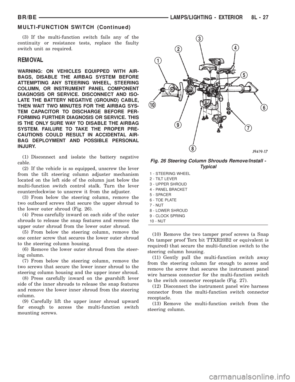
(3) If the multi-function switch fails any of the
continuity or resistance tests, replace the faulty
switch unit as required.
REMOVAL
WARNING: ON VEHICLES EQUIPPED WITH AIR-
BAGS, DISABLE THE AIRBAG SYSTEM BEFORE
ATTEMPTING ANY STEERING WHEEL, STEERING
COLUMN, OR INSTRUMENT PANEL COMPONENT
DIAGNOSIS OR SERVICE. DISCONNECT AND ISO-
LATE THE BATTERY NEGATIVE (GROUND) CABLE,
THEN WAIT TWO MINUTES FOR THE AIRBAG SYS-
TEM CAPACITOR TO DISCHARGE BEFORE PER-
FORMING FURTHER DIAGNOSIS OR SERVICE. THIS
IS THE ONLY SURE WAY TO DISABLE THE AIRBAG
SYSTEM. FAILURE TO TAKE THE PROPER PRE-
CAUTIONS COULD RESULT IN ACCIDENTAL AIR-
BAG DEPLOYMENT AND POSSIBLE PERSONAL
INJURY.
(1) Disconnect and isolate the battery negative
cable.
(2) If the vehicle is so equipped, unscrew the lever
from the tilt steering column adjuster mechanism
located on the left side of the column just below the
multi-function switch control stalk. Turn the lever
counterclockwise to unscrew it from the adjuster.
(3) From below the steering column, remove the
two outboard screws that secure the upper shroud to
the lower outer shroud (Fig. 26).
(4) Press carefully inward on each side of the outer
shrouds to release the snap features and remove the
upper outer shroud from the lower outer shroud.
(5) From below the steering column, remove the
one center screw that secures the lower outer shroud
to the steering column housing.
(6) Remove the lower outer shroud from the steer-
ing column.
(7) From below the steering column, remove the
two screws that secure the lower inner shroud to the
steering column housing and the upper inner shroud.
(8) Press carefully inward on the gearshift lever
side of the inner shrouds to release the snap features
and remove the lower inner shroud from the steering
column.
(9) Carefully lift the upper inner shroud upward
far enough to access the multi-function switch
mounting screws.(10) Remove the two tamper proof screws (a Snap
On tamper proof Torx bit TTXR20B2 or equivalent is
required) that secure the multi-function switch to the
steering column housing.
(11) Gently pull the multi-function switch away
from the steering column far enough to access and
remove the screw that secures the instrument panel
wire harness connector for the multi-function switch
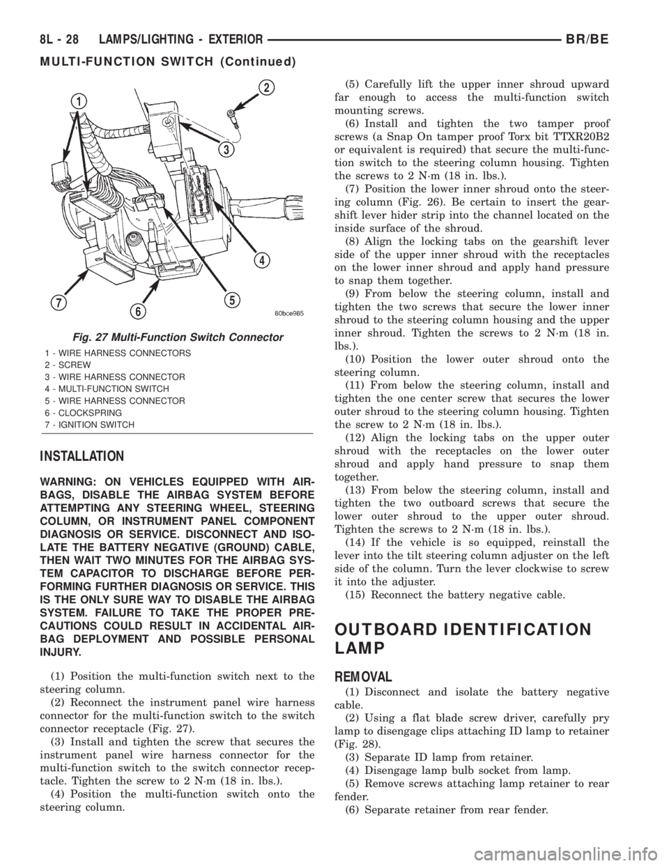
to the switch connector receptacle (Fig. 27).
(12) Disconnect the instrument panel wire harness
connector from the multi-function switch connector
receptacle.
(13) Remove the multi-function switch from the
steering column.
Fig. 26 Steering Column Shrouds Remove/Install -
Typical
1 - STEERING WHEEL
2 - TILT LEVER
3 - UPPER SHROUD
4 - PANEL BRACKET
5 - SPACER
6 - TOE PLATE
7 - NUT
8 - LOWER SHROUD
9 - CLOCK SPRING
10 - NUT
BR/BELAMPS/LIGHTING - EXTERIOR 8L - 27
MULTI-FUNCTION SWITCH (Continued)
Page 543 of 2255
INSTALLATION
WARNING: ON VEHICLES EQUIPPED WITH AIR-
BAGS, DISABLE THE AIRBAG SYSTEM BEFORE
ATTEMPTING ANY STEERING WHEEL, STEERING
COLUMN, OR INSTRUMENT PANEL COMPONENT
DIAGNOSIS OR SERVICE. DISCONNECT AND ISO-
LATE THE BATTERY NEGATIVE (GROUND) CABLE,
THEN WAIT TWO MINUTES FOR THE AIRBAG SYS-
TEM CAPACITOR TO DISCHARGE BEFORE PER-
FORMING FURTHER DIAGNOSIS OR SERVICE. THIS
IS THE ONLY SURE WAY TO DISABLE THE AIRBAG
SYSTEM. FAILURE TO TAKE THE PROPER PRE-
CAUTIONS COULD RESULT IN ACCIDENTAL AIR-
BAG DEPLOYMENT AND POSSIBLE PERSONAL
INJURY.
(1) Position the multi-function switch next to the
steering column.
(2) Reconnect the instrument panel wire harness
connector for the multi-function switch to the switch
connector receptacle (Fig. 27).
(3) Install and tighten the screw that secures the
instrument panel wire harness connector for the
multi-function switch to the switch connector recep-
tacle. Tighten the screw to 2 N´m (18 in. lbs.).
(4) Position the multi-function switch onto the
steering column.(5) Carefully lift the upper inner shroud upward
far enough to access the multi-function switch
mounting screws.
(6) Install and tighten the two tamper proof
screws (a Snap On tamper proof Torx bit TTXR20B2
or equivalent is required) that secure the multi-func-
tion switch to the steering column housing. Tighten
the screws to 2 N´m (18 in. lbs.).
(7) Position the lower inner shroud onto the steer-
ing column (Fig. 26). Be certain to insert the gear-
shift lever hider strip into the channel located on the
inside surface of the shroud.
(8) Align the locking tabs on the gearshift lever
side of the upper inner shroud with the receptacles
on the lower inner shroud and apply hand pressure
to snap them together.
(9) From below the steering column, install and
tighten the two screws that secure the lower inner
shroud to the steering column housing and the upper
inner shroud. Tighten the screws to 2 N´m (18 in.
lbs.).
(10) Position the lower outer shroud onto the
steering column.
(11) From below the steering column, install and
tighten the one center screw that secures the lower
outer shroud to the steering column housing. Tighten
the screw to 2 N´m (18 in. lbs.).
(12) Align the locking tabs on the upper outer
shroud with the receptacles on the lower outer
shroud and apply hand pressure to snap them
together.
(13) From below the steering column, install and
tighten the two outboard screws that secure the
lower outer shroud to the upper outer shroud.
Tighten the screws to 2 N´m (18 in. lbs.).
(14) If the vehicle is so equipped, reinstall the
lever into the tilt steering column adjuster on the left
side of the column. Turn the lever clockwise to screw
it into the adjuster.
(15) Reconnect the battery negative cable.
OUTBOARD IDENTIFICATION
LAMP
REMOVAL
(1) Disconnect and isolate the battery negative
cable.
(2) Using a flat blade screw driver, carefully pry
lamp to disengage clips attaching ID lamp to retainer
(Fig. 28).
(3) Separate ID lamp from retainer.
(4) Disengage lamp bulb socket from lamp.
(5) Remove screws attaching lamp retainer to rear
fender.
(6) Separate retainer from rear fender.
Fig. 27 Multi-Function Switch Connector
1 - WIRE HARNESS CONNECTORS
2 - SCREW
3 - WIRE HARNESS CONNECTOR
4 - MULTI-FUNCTION SWITCH
5 - WIRE HARNESS CONNECTOR
6 - CLOCKSPRING
7 - IGNITION SWITCH
8L - 28 LAMPS/LIGHTING - EXTERIORBR/BE
MULTI-FUNCTION SWITCH (Continued)
Page 595 of 2255
²Airbag Control Module- The Airbag Control
Module (ACM) is located in a stamped mounting
bracket on the floor panel transmission tunnel, below
the center of the instrument panel.
²Airbag Indicator- The airbag indicator is inte-
gral to the ElectroMechanical Instrument Cluster
(EMIC), which is located on the instrument panel in
front of the driver.
²Clockspring- The clockspring is located near
the top of the steering column, directly beneath the
steering wheel.
²Driver Airbag- The driver airbag is located in
the center of the steering wheel, beneath the driver
airbag trim cover.
²Driver Knee Blocker- The driver knee blocker
is a molded plastic structural unit secured to the
back side of and integral to the instrument panel
steering column opening cover.
²Passenger Airbag- The passenger airbag is
located on the instrument panel, beneath the passen-
ger airbag door on the instrument panel above the
glove box on the passenger side of the vehicle.
²Passenger Airbag On/Off Switch- The pas-
senger airbag on/off switch is located in a dedicated
opening in the upper right corner of the instrument
panel cluster bezel, to the right of the center panel
outlets of the climate control system.
²Passenger Knee Blocker- The passenger knee
blocker is a structural reinforcement that is integral
to and concealed within the glove box door.
The ACM and the EMIC each contain a central
processing unit and programming that allow them to
communicate with each other using the Chrysler Col-
lision Detection (CCD) data bus network. This
method of communication is used for control of the
airbag indicator on all models. (Refer to 8 - ELEC-
TRICAL/ELECTRONIC CONTROL MODULES/
COMMUNICATION - DESCRIPTION).Hard wired circuitry connects the airbag system
components to each other through the electrical sys-
tem of the vehicle. These hard wired circuits are
integral to several wire harnesses, which are routed
throughout the vehicle and retained by many differ-
ent methods. These circuits may be connected to each
other, to the vehicle electrical system, and to the air-
bag system components through the use of a combi-
nation of soldered splices, splice block connectors,
and many different types of wire harness terminal
connectors and insulators. Refer to the appropriate
wiring information. The wiring information includes
wiring diagrams, proper wire and connector repair
procedures, further details on wire harness routing
and retention, as well as pin-out and location views
for the various wire harness connectors, splices and
grounds.OPERATION
The airbag system is referred to as a supplemental
restraint system because it was designed and is
intended to enhance the protection for the front seat
occupants of the vehicleonlywhen used in conjunc-
tion with the seat belts. It is referred to as a passive
system because the vehicle occupants are not
required to do anything to make it work. The pri-
mary passenger restraints in this or any other vehi-
cle are the standard equipment factory-installed seat
belts. Seat belts are referred to as an active restraint
because the vehicle occupants are required to physi-
cally fasten and properly adjust these restraints in
order to benefit from them. The vehicle occupants
must be wearing their seat belts in order to obtain
the maximum safety benefit from the factory-in-
stalled airbag system.
The airbag system electrical circuits are continu-
ously monitored and controlled by a microprocessor
and software contained within the Airbag Control
Module (ACM). An airbag indicator in the ElectroMe-
chanical Instrument Cluster (EMIC) lights for about
seven seconds as a bulb test each time the ignition
switch is turned to the On or Start positions. Follow-
ing the bulb test, the airbag indicator is turned on or
off by the ACM to indicate the status of the airbag
system. If the airbag indicator comes on at any time
other than during the bulb test, it indicates that
there is a problem in the airbag system electrical cir-
cuits. Such a problem may cause the airbags not to
deploy when required, or to deploy when not
required.
The clockspring on the top of the steering column
allows a continuous electrical circuit to be main-
tained between the stationary steering column and
the driver airbag inflator, which rotates with the
steering wheel. The passenger airbag on/off switch
allows the passenger side airbag to be disabled when
Fig. 1 SRS Logo
8O - 2 RESTRAINTSBR/BE
RESTRAINTS (Continued)