2002 DODGE RAM steering wheel
[x] Cancel search: steering wheelPage 84 of 2255

AXLE SHAFTS
REMOVAL
(1) Raise and support the vehicle.
(2) Remove wheel and tire assembly.
(3) Remove brake caliper, rotor and ABS wheel
speed sensor if equipped. Refer to 5 Brakes for pro-
cedures.
(4) Remove the cotter pin and axle hub nut.
(5) Remove hub bearing bolts (Fig. 21) and remove
hub bearing from the steering knuckle.
(6) Remove brake dust shield from knuckle.
(7) Remove axle shaft from the housing. Avoid
damaging the axle shaft oil seal.
INSTALLATION
(1) Clean axle shaft and apply a thin film of
Mopar Wheel Bearing Grease to the shaft splines,
seal contact surface, hub bore.
(2) Install axle shaft into the housing and differen-
tial side gears. Avoid damaging axle shaft oil seals in
the differential.
(3) Install dust shield and hub bearing on knuckle.
(4) Install hub bearing bolts and tighten to 170
N´m (125 ft. lbs.).
(5) Install axle washer and nut, tighten nut to 237
N´m (175 ft. lbs.). Align nut to next cotter pin hole
and install new cotter pin.
(6) Install ABS wheel speed sensor, brake rotor
and caliper. Refer to Brakes for proper procedures.
(7) Install wheel and tire assembly.
(8) Remove support and lower the vehicle.
BLOCK, ADAPTER ± C-239-37
BLOCK, ADAPTER ± C-239-62
HOLDER, YOKE - 6719A
PINION DEPTH, SET ± 6730
Fig. 21 HUB AND KNUCKLE
1 - KNUCKLE
2 - HUB BEARING
BR/BEFRONT AXLE - 248FBI 3 - 29
FRONT AXLE - 248FBI (Continued)
Page 194 of 2255

CAUTION: Never use gasoline, kerosene, alcohol,
motor oil, transmission fluid, or any fluid containing
mineral oil to clean the system components. These
fluids damage rubber cups and seals. Use only
fresh brake fluid or Mopar brake cleaner to clean or
flush brake system components. These are the only
cleaning materials recommended. If system contam-
ination is suspected, check the fluid for dirt, discol-
oration, or separation into distinct layers. Also
check the reservoir cap seal for distortion. Drain
and flush the system with new brake fluid if con-
tamination is suspected.
CAUTION: Use Mopar brake fluid, or an equivalent
quality fluid meeting SAE/DOT standards J1703 and
DOT 3. Brake fluid must be clean and free of con-
taminants. Use fresh fluid from sealed containers
only to ensure proper antilock component opera-
tion.
CAUTION: Use Mopar multi-mileage or high temper-
ature grease to lubricate caliper slide surfaces,
drum brake pivot pins, and shoe contact points on
the backing plates. Use multi-mileage grease or GE
661 or Dow 111 silicone grease on caliper slide pins
to ensure proper operation.
DIAGNOSIS AND TESTING - BASE BRAKE
SYSTEM
Base brake components consist of the brake shoes,
calipers, wheel cylinders, brake drums, rotors, brake
lines, master cylinder, booster, and parking brake
components.
Brake diagnosis involves determining if the prob-
lem is related to a mechanical, hydraulic, or vacuum
operated component.
The first diagnosis step is the preliminary check.
PRELIMINARY BRAKE CHECK
(1) Check condition of tires and wheels. Damaged
wheels and worn, damaged, or underinflated tires
can cause pull, shudder, vibration, and a condition
similar to grab.
(2) If complaint was based on noise when braking,
check suspension components. Jounce front and rear
of vehicle and listen for noise that might be caused
by loose, worn or damaged suspension or steering
components.
(3) Inspect brake fluid level and condition. Note
that the brake reservoir fluid level will decrease in
proportion to normal lining wear.Also note that
brake fluid tends to darken over time. This is
normal and should not be mistaken for contam-
ination.(a) If fluid level is abnormally low, look for evi-
dence of leaks at calipers, wheel cylinders, brake
lines, and master cylinder.
(b) If fluid appears contaminated, drain out a
sample to examine. System will have to be flushed
if fluid is separated into layers, or contains a sub-
stance other than brake fluid. The system seals
and cups will also have to be replaced after flush-
ing. Use clean brake fluid to flush the system.
(4) Check parking brake operation. Verify free
movement and full release of cables and pedal. Also
note if vehicle was being operated with parking
brake partially applied.
(5) Check brake pedal operation. Verify that pedal
does not bind and has adequate free play. If pedal
lacks free play, check pedal and power booster for
being loose or for bind condition. Do not road test
until condition is corrected.
(6) Check booster vacuum check valve and hose.
(7) If components checked appear OK, road test
the vehicle.
ROAD TESTING
(1) If complaint involved low brake pedal, pump
pedal and note if it comes back up to normal height.
(2) Check brake pedal response with transmission
in Neutral and engine running. Pedal should remain
firm under constant foot pressure.
(3) During road test, make normal and firm brake
stops in 25-40 mph range. Note faulty brake opera-
tion such as low pedal, hard pedal, fade, pedal pulsa-
tion, pull, grab, drag, noise, etc.
(4) Attempt to stop the vehicle with the parking
brake only and note grab, drag, noise, etc.
PEDAL FALLS AWAY
A brake pedal that falls away under steady foot
pressure is generally the result of a system leak. The
leak point could be at a brake line, fitting, hose, or
caliper/wheel cylinder. If leakage is severe, fluid will
be evident at or around the leaking component.
Internal leakage (seal by-pass) in the master cylin-
der caused by worn or damaged piston cups, may
also be the problem cause.
An internal leak in the ABS or RWAL system may
also be the problem with no physical evidence.
LOW PEDAL
If a low pedal is experienced, pump the pedal sev-
eral times. If the pedal comes back up, worn linings,
rotors, drums, or rear brakes out of adjustment are
the most likely causes. The proper course of action is
to inspect and replace all worn component and make
the proper adjustments.
BR/BEBRAKES - BASE 5 - 5
HYDRAULIC/MECHANICAL (Continued)
Page 196 of 2255

mile or two. However, if the lining is both soaked and
dirt contaminated, cleaning and/or replacement will
be necessary.
BRAKE LINING CONTAMINATION
Brake lining contamination is mostly a product of
leaking calipers or wheel cylinders, worn seals, driv-
ing through deep water puddles, or lining that has
become covered with grease and grit during repair.
Contaminated lining should be replaced to avoid fur-
ther brake problems.
WHEEL AND TIRE PROBLEMS
Some conditions attributed to brake components
may actually be caused by a wheel or tire problem.
A damaged wheel can cause shudder, vibration and
pull. A worn or damaged tire can also cause pull.
Severely worn tires with very little tread left can
produce a grab-like condition as the tire loses and
recovers traction. Flat-spotted tires can cause vibra-
tion and generate shudder during brake operation. A
tire with internal damage such as a severe bruise,
cut, or ply separation can cause pull and vibration.
BRAKE NOISES
Some brake noise is common with rear drum
brakes and on some disc brakes during the first few
stops after a vehicle has been parked overnight or
stored. This is primarily due to the formation of trace
corrosion (light rust) on metal surfaces. This light
corrosion is typically cleared from the metal surfaces
after a few brake applications causing the noise to
subside.
BRAKE SQUEAK/SQUEAL
Brake squeak or squeal may be due to linings that
are wet or contaminated with brake fluid, grease, or
oil. Glazed linings and rotors with hard spots can
also contribute to squeak. Dirt and foreign material
embedded in the brake lining will also cause squeak/
squeal.
A very loud squeak or squeal is frequently a sign of
severely worn brake lining. If the lining has worn
through to the brake shoes in spots, metal-to-metal
contact occurs. If the condition is allowed to continue,
rotors and drums can become so scored that replace-
ment is necessary.
BRAKE CHATTER
Brake chatter is usually caused by loose or worn
components, or glazed/burnt lining. Rotors with hard
spots can also contribute to chatter. Additional causes
of chatter are out-of-tolerance rotors, brake lining not
securely attached to the shoes, loose wheel bearings
and contaminated brake lining.THUMP/CLUNK NOISE
Thumping or clunk noises during braking are fre-
quentlynotcaused by brake components. In many
cases, such noises are caused by loose or damaged
steering, suspension, or engine components. However,
calipers that bind on the slide surfaces can generate
a thump or clunk noise. In addition, worn out,
improperly adjusted, or improperly assembled rear
brake shoes can also produce a thump noise.
STANDARD PROCEDURE
STANDARD PROCEDURE - MANUAL BLEEDING
Use Mopar brake fluid, or an equivalent quality
fluid meeting SAE J1703-F and DOT 3 standards
only. Use fresh, clean fluid from a sealed container at
all times.
(1) Remove reservoir filler caps and fill reservoir.
(2) If calipers, or wheel cylinders were overhauled,
open all caliper and wheel cylinder bleed screws.
Then close each bleed screw as fluid starts to drip
from it. Top off master cylinder reservoir once more
before proceeding.
(3) Attach one end of bleed hose to bleed screw
and insert opposite end in glass container partially
filled with brake fluid (Fig. 1). Be sure end of bleed
hose is immersed in fluid.
(4)
Open up bleeder, then have a helper press down
the brake pedal. Once the pedal is down close the
bleeder. Repeat bleeding until fluid stream is clear and
free of bubbles. Then move to the next wheel.
Fig. 1 Bleed Hose Setup
1 - BLEED HOSE
2 - FLUID CONTAINER PARTIALLY FILLED WITH FLUID
BR/BEBRAKES - BASE 5 - 7
HYDRAULIC/MECHANICAL (Continued)
Page 204 of 2255
(8) Remove the supports and lower the vehicle.
(9) Verify a firm pedal before moving the vehicle.
FLUID
DIAGNOSIS AND TESTING - BRAKE FLUID
CONTAMINATION
Indications of fluid contamination are swollen or
deteriorated rubber parts.
Swollen rubber parts indicate the presence of
petroleum in the brake fluid.
To test for contamination, put a small amount of
drained brake fluid in clear glass jar. If fluid sepa-
rates into layers, there is mineral oil or other fluid
contamination of the brake fluid.
If brake fluid is contaminated, drain and thor-
oughly flush system. Replace master cylinder, propor-
tioning valve, caliper seals, wheel cylinder seals,
Antilock Brakes hydraulic unit and all hydraulic
fluid hoses.
STANDARD PROCEDURE - BRAKE FLUID
LEVEL
Always clean the master cylinder reservoir and
caps before checking fluid level. If not cleaned, dirt
could enter the fluid.
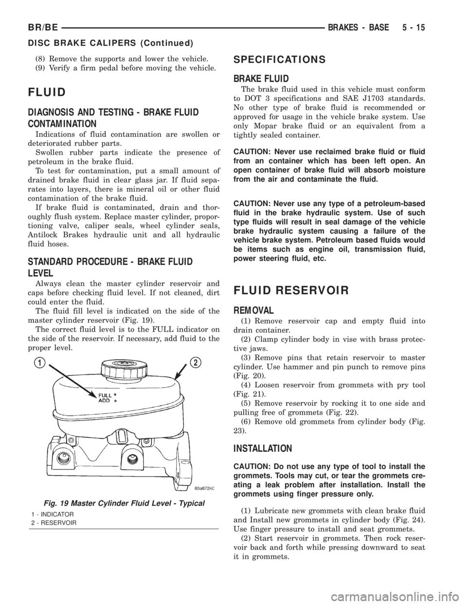
The fluid fill level is indicated on the side of the
master cylinder reservoir (Fig. 19).
The correct fluid level is to the FULL indicator on
the side of the reservoir. If necessary, add fluid to the
proper level.
SPECIFICATIONS
BRAKE FLUID
The brake fluid used in this vehicle must conform
to DOT 3 specifications and SAE J1703 standards.
No other type of brake fluid is recommended or
approved for usage in the vehicle brake system. Use
only Mopar brake fluid or an equivalent from a
tightly sealed container.
CAUTION: Never use reclaimed brake fluid or fluid
from an container which has been left open. An
open container of brake fluid will absorb moisture
from the air and contaminate the fluid.
CAUTION: Never use any type of a petroleum-based
fluid in the brake hydraulic system. Use of such
type fluids will result in seal damage of the vehicle
brake hydraulic system causing a failure of the
vehicle brake system. Petroleum based fluids would
be items such as engine oil, transmission fluid,
power steering fluid, etc.
FLUID RESERVOIR
REMOVAL
(1) Remove reservoir cap and empty fluid into
drain container.
(2) Clamp cylinder body in vise with brass protec-
tive jaws.
(3) Remove pins that retain reservoir to master
cylinder. Use hammer and pin punch to remove pins
(Fig. 20).
(4) Loosen reservoir from grommets with pry tool
(Fig. 21).
(5) Remove reservoir by rocking it to one side and
pulling free of grommets (Fig. 22).
(6) Remove old grommets from cylinder body (Fig.
23).
INSTALLATION
CAUTION: Do not use any type of tool to install the
grommets. Tools may cut, or tear the grommets cre-
ating a leak problem after installation. Install the
grommets using finger pressure only.
(1) Lubricate new grommets with clean brake fluid
and Install new grommets in cylinder body (Fig. 24).
Use finger pressure to install and seat grommets.
(2) Start reservoir in grommets. Then rock reser-
voir back and forth while pressing downward to seat
it in grommets.
Fig. 19 Master Cylinder Fluid Level - Typical
1 - INDICATOR
2 - RESERVOIR
BR/BEBRAKES - BASE 5 - 15
DISC BRAKE CALIPERS (Continued)
Page 207 of 2255
EXTERIOR/BRAKE LAMP SWITCH - INSTALLA-
TION).
(10) Install knee bolster, (Refer to 23 - BODY/IN-
STRUMENT PANEL/STEERING COLUMN OPEN-
ING COVER - INSTALLATION).
POWER BRAKE BOOSTER
DIAGNOSIS AND TESTING - HYDRAULIC
BOOSTER
The hydraulic booster uses hydraulic pressure from
the power steering pump. Before diagnosing a
booster problem, first verify the power steering pump
is operating properly. Perform the following checks.
²Check the power steering fluid level.
²Check the brake fluid level.
²Check all power steering hoses and lines for
leaks and restrictions.
²Check power steering pump pressure.
NOISES
The hydraulic booster unit will produce certain
characteristic booster noises. The noises may occur
when the brake pedal is used in a manner not asso-
ciated with normal braking or driving habits.
HISSING
A hissing noise may be noticed when above normal
brake pedal pressure is applied, 40 lbs. or above. The
noise will be more noticeable if the vehicle is not
moving. The noise will increase with the brake pedal
pressure and an increase of system operating temper-
ature.
CLUNK-CHATTER-CLICKING
A clunk-chatter-clicking may be noticed when the
brake pedal is released quickly, after above normal
brake pedal pressure is applied 50-100 lbs..
BOOSTER FUNCTION TEST
With the engine off depress the brake pedal several
times to discharge the accumulator. Then depress the
brake pedal using 40 lbs. of force and start the
engine. The brake pedal should fall and then push
back against your foot. This indicates the booster is
operating properly.
ACCUMULATOR LEAKDOWN
(1) Start the engine, apply the brakes and turn the
steering wheel from lock to lock. This will ensure the
accumulator is charged. Turn off the engine and let
the vehicle sit for one hour. After one hour there
should be at least two power assisted brake applica-
tion with the engine off. If the system does not retain
a charge the booster must be replaced.(2) With the engine off depress the brake pedal
several times to discharge the accumulator. Grasp
the accumulator and see if it wobbles or turns. If it
does the accumulator has lost a gas charge and the
booster must be replaced.
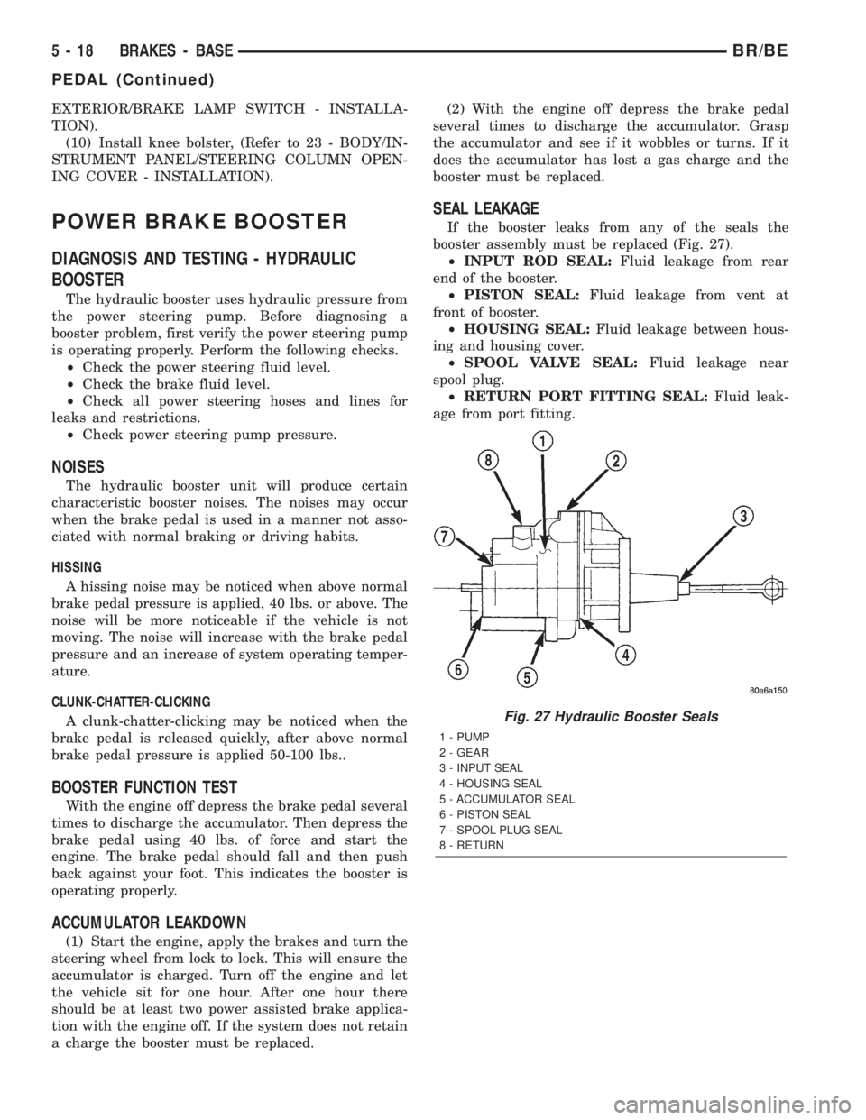
SEAL LEAKAGE
If the booster leaks from any of the seals the
booster assembly must be replaced (Fig. 27).
²INPUT ROD SEAL:Fluid leakage from rear
end of the booster.
²PISTON SEAL:Fluid leakage from vent at
front of booster.
²HOUSING SEAL:Fluid leakage between hous-
ing and housing cover.
²SPOOL VALVE SEAL:Fluid leakage near
spool plug.
²RETURN PORT FITTING SEAL:Fluid leak-
age from port fitting.
Fig. 27 Hydraulic Booster Seals
1 - PUMP
2 - GEAR
3 - INPUT SEAL
4 - HOUSING SEAL
5 - ACCUMULATOR SEAL
6 - PISTON SEAL
7 - SPOOL PLUG SEAL
8 - RETURN
5 - 18 BRAKES - BASEBR/BE
PEDAL (Continued)
Page 208 of 2255
HYDRAULIC BOOSTER DIAGNOSIS CHART
CONDITION POSSIBLE CAUSES CORRECTION
Slow Brake Pedal Return 1. Excessive seal friction in booster. 1. Replace booster.
2. Faulty spool valve action. 2. Replace booster.
3. Restriction in booster return hose. 3. Replace hose.
4. Damaged input rod. 4. Replace booster.
Excessive Brake Pedal
Effort.1. Internal or external seal leakage. 1. Replace booster.
2. Faulty steering pump. 2. Replace pump.
Brakes Self Apply 1. Dump valve faulty. 1. Replace booster.
2. Contamination in hydraulic
system.2. Flush hydraulic system and replace
booster.
3. Restriction in booster return hose. 3. Replace hose.
Booster Chatter, Pedal
Vibration1. Slipping pump belt. 1. Replace power steering belt.
2. Low pump fluid level. 2. Fill pump and check for leaks.
Grabbing Brakes 1. Low pump flow. 1. Test and repair/replace pump.
2. Faulty spool valve action. 2. Replace booster.
STANDARD PROCEDURE - BLEEDING
The hydraulic booster is generally self-bleeding,
this procedure will normally bleed the air from the
booster. Normal driving and operation of the unit will
remove any remaining trapped air.
(1) Fill power steering pump reservoir.
(2) Disconnect fuel shutdown relay and crank the
engine for several seconds, Refer to Fuel System for
relay location and WARNING.
(3) Check fluid level and add if necessary.
(4) Connect fuel shutdown relay and start the
engine.
(5) Turn the steering wheel slowly from lock to
lock twice.
(6) Stop the engine and discharge the accumulator
by depressing the brake pedal 5 times.
(7) Start the engine and turn the steering wheel
slowly from lock to lock twice.
(8) Turn off the engine and check fluid level and
add if necessary.
NOTE: If fluid foaming occurs, wait for foam to dis-
sipate and repeat steps 7 and 8.
REMOVAL
NOTE: If the booster is being replaced because the
power steering fluid is contaminated, flush the
power steering system before replacing the booster.(1) With engine off depress the brake pedal 5
times to discharge the accumulator.
(2) Remove brake lines from master cylinder.
(3) Remove mounting nuts from the master cylin-
der.
(4) Remove the bracket from the hydraulic booster
lines and master cylinder mounting studs.
(5) Remove the master cylinder.
(6) Remove the return hose and the two pressure
lines from the hydraulic booster (Fig. 28).
(7) Remove the booster push rod clip, washer and
rod remove from the brake pedal. (Fig. 29).
(8) Remove the mounting nuts from the hydraulic
booster and remove the booster (Fig. 30).
INSTALLATION
(1) Install the hydraulic booster and tighten the
mounting nuts to 28 N´m (21 ft. lbs.).
(2) Install the booster push rod, washer and clip
onto the brake pedal.
(3) Install the master cylinder on the mounting
studs. and tighten the mounting nuts to 23 N´m (17
ft. lbs.).
(4) Install the brake lines to the master cylinder
and tighten to 19-200 N´m (170-200 in. lbs.).
(5) Install the hydraulic booster line bracket onto
the master cylinder mounting studs.
(6) Install the master cylinder mounting nuts and
tighten to 23 N´m (17 ft. lbs.).
BR/BEBRAKES - BASE 5 - 19
POWER BRAKE BOOSTER (Continued)
Page 211 of 2255
REMOVAL - FRONT ± 2500
(1) Raise and support the vehicle.
(2) Remove the wheel and tire assembly.
(3) Remove the caliper from the steering knuckle,
(Refer to 5 - BRAKES/HYDRAULIC/MECHANICAL/
DISC BRAKE CALIPERS - REMOVAL) and remove
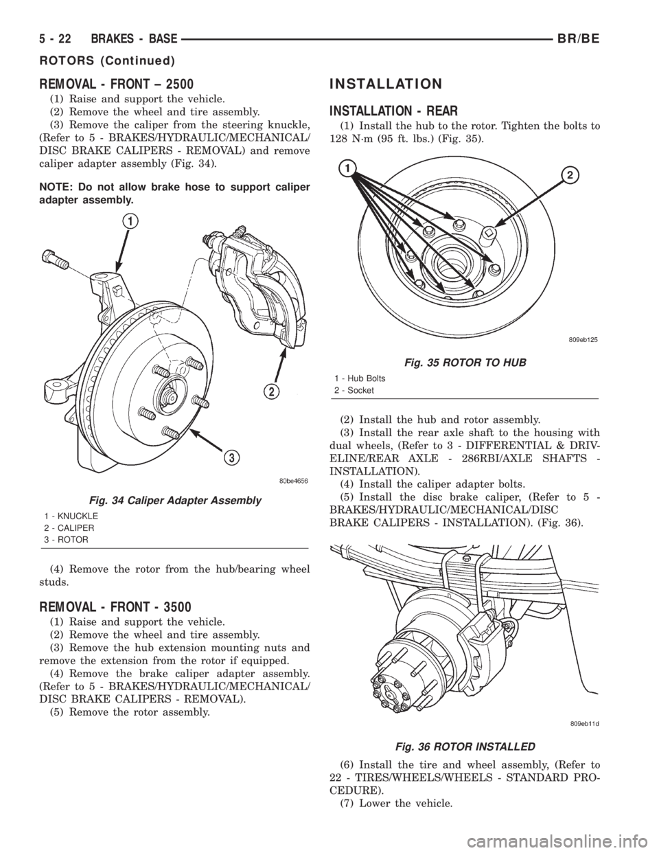
caliper adapter assembly (Fig. 34).
NOTE: Do not allow brake hose to support caliper
adapter assembly.
(4) Remove the rotor from the hub/bearing wheel
studs.
REMOVAL - FRONT - 3500
(1) Raise and support the vehicle.
(2) Remove the wheel and tire assembly.
(3) Remove the hub extension mounting nuts and
remove the extension from the rotor if equipped.
(4) Remove the brake caliper adapter assembly.
(Refer to 5 - BRAKES/HYDRAULIC/MECHANICAL/
DISC BRAKE CALIPERS - REMOVAL).
(5) Remove the rotor assembly.
INSTALLATION
INSTALLATION - REAR
(1) Install the hub to the rotor. Tighten the bolts to
128 N´m (95 ft. lbs.) (Fig. 35).
(2) Install the hub and rotor assembly.
(3) Install the rear axle shaft to the housing with
dual wheels, (Refer to 3 - DIFFERENTIAL & DRIV-
ELINE/REAR AXLE - 286RBI/AXLE SHAFTS -
INSTALLATION).
(4) Install the caliper adapter bolts.
(5) Install the disc brake caliper, (Refer to 5 -
BRAKES/HYDRAULIC/MECHANICAL/DISC
BRAKE CALIPERS - INSTALLATION). (Fig. 36).
(6) Install the tire and wheel assembly, (Refer to
22 - TIRES/WHEELS/WHEELS - STANDARD PRO-
CEDURE).
(7) Lower the vehicle.
Fig. 34 Caliper Adapter Assembly
1 - KNUCKLE
2 - CALIPER
3 - ROTOR
Fig. 35 ROTOR TO HUB
1 - Hub Bolts
2 - Socket
Fig. 36 ROTOR INSTALLED
5 - 22 BRAKES - BASEBR/BE
ROTORS (Continued)
Page 224 of 2255
BRAKES - ABS
TABLE OF CONTENTS
page page
BRAKES - ABS
DESCRIPTION.........................35
OPERATION...........................36
DIAGNOSIS AND TESTING - ANTILOCK
BRAKES............................36
STANDARD PROCEDURE
STANDARD PROCEDURE - RWAL SERVICE
PRECAUTIONS.......................36
STANDARD PROCEDURE - BLEEDING ABS
BRAKE SYSTEM......................36
SPECIFICATIONS
TORQUE CHART......................37
FRONT WHEEL SPEED SENSOR
DESCRIPTION.........................38
OPERATION...........................38
REMOVAL
REMOVAL - 4X2......................39REMOVAL - 4X4......................39
INSTALLATION
INSTALLATION - 4X2...................39
INSTALLATION - 4X4...................39
REAR WHEEL SPEED SENSOR
DIAGNOSIS AND TESTING - REAR WHEEL
SPEED SENSOR......................40
REMOVAL.............................40
INSTALLATION.........................40
HCU (HYDRAULIC CONTROL UNIT)
DESCRIPTION.........................40
OPERATION...........................40
REMOVAL.............................41
INSTALLATION.........................41
BRAKES - ABS
DESCRIPTION
The antilock brake system (ABS) is an electroni-
cally operated, all wheel brake control system. 2500
and 3500 vehicles have Electronic Brake Distribution
(EBD) designed into the systen which eliminates the
combination/proportioning valve.
The system is designed to prevent wheel lockup
and maintain steering control during periods of high
wheel slip when braking. Preventing lockup is accom-
plished by modulating fluid pressure to the wheel
brake units.
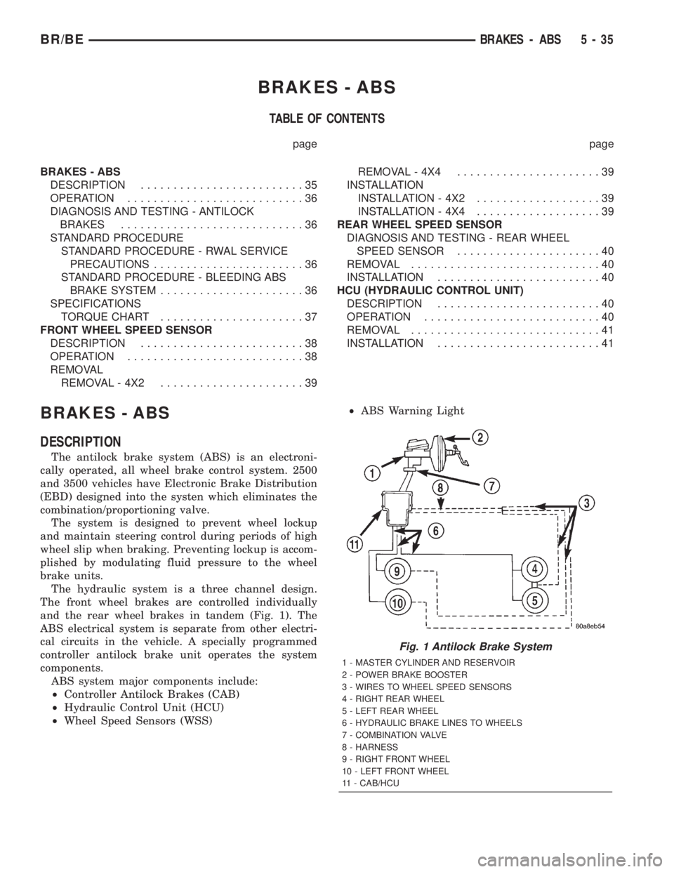
The hydraulic system is a three channel design.
The front wheel brakes are controlled individually
and the rear wheel brakes in tandem (Fig. 1). The
ABS electrical system is separate from other electri-
cal circuits in the vehicle. A specially programmed
controller antilock brake unit operates the system
components.
ABS system major components include:
²Controller Antilock Brakes (CAB)
²Hydraulic Control Unit (HCU)
²Wheel Speed Sensors (WSS)²ABS Warning Light
Fig. 1 Antilock Brake System
1 - MASTER CYLINDER AND RESERVOIR
2 - POWER BRAKE BOOSTER
3 - WIRES TO WHEEL SPEED SENSORS
4 - RIGHT REAR WHEEL
5 - LEFT REAR WHEEL
6 - HYDRAULIC BRAKE LINES TO WHEELS
7 - COMBINATION VALVE
8 - HARNESS
9 - RIGHT FRONT WHEEL
10 - LEFT FRONT WHEEL
11 - CAB/HCU
BR/BEBRAKES - ABS 5 - 35