2002 DODGE RAM sensor
[x] Cancel search: sensorPage 1039 of 2255
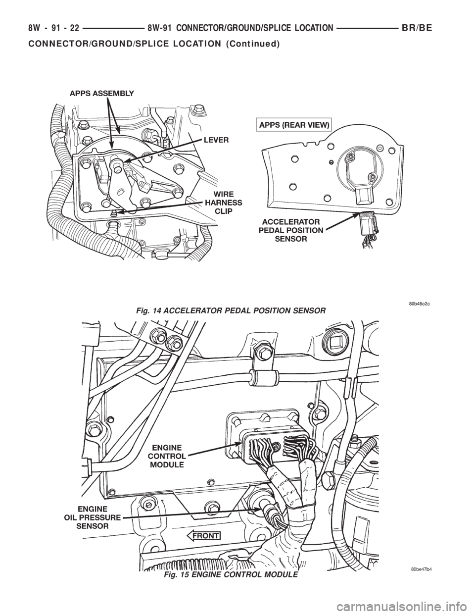
Fig. 14 ACCELERATOR PEDAL POSITION SENSOR
Fig. 15 ENGINE CONTROL MODULE
8W - 91 - 22 8W-91 CONNECTOR/GROUND/SPLICE LOCATIONBR/BE
CONNECTOR/GROUND/SPLICE LOCATION (Continued)
Page 1189 of 2255
CRANKSHAFT REAR OIL SEAL RETAINER
REMOVAL............................162
INSTALLATION........................163
SOLID LIFTERS/TAPPETS
REMOVAL............................164
CLEANING...........................164
INSPECTION.........................165
INSTALLATION........................165
PISTON & CONNECTING ROD
DESCRIPTION........................165
STANDARD PROCEDUREÐPISTON
GRADING..........................166
REMOVAL............................168
CLEANING...........................169
INSPECTION
INSPECTION........................169
Connecting Rods.....................169
INSTALLATION........................170
PISTON RINGS
STANDARD PROCEDURE - PISTON RING
FITTING............................171
VIBRATION DAMPER
REMOVAL............................172
INSPECTION.........................172
INSTALLATION........................173
FRONT MOUNT
REMOVAL............................173
INSTALLATION........................174
REAR MOUNT
REMOVAL............................174
INSTALLATION........................174
LUBRICATION
DESCRIPTION........................174
OPERATION..........................174
DIAGNOSIS AND TESTINGÐENGINE OIL
PRESSURE.........................178
OIL
STANDARD PROCEDURE
STANDARD PROCEDURE - ENGINE OIL
LEVEL.............................178
STANDARD PROCEDURE - ENGINE OIL
SERVICE...........................178OIL COOLER & LINES
CLEANING AND INSPECTION............179
OIL FILTER
REMOVAL............................179
INSTALLATION........................179
OIL PAN
REMOVAL............................179
CLEANING...........................179
INSPECTION.........................179
INSTALLATION........................180
OIL PRESSURE RELIEF VALVE
REMOVAL............................180
CLEANING...........................180
INSPECTION.........................180
INSTALLATION........................180
OIL PRESSURE SENSOR/SWITCH
REMOVAL............................181
INSTALLATION........................181
OIL PUMP
REMOVAL............................181
CLEANING...........................181
INSPECTION.........................181
INSTALLATION........................182
INTAKE MANIFOLD
REMOVAL............................184
CLEANING...........................184
INSPECTION.........................184
INSTALLATION........................184
EXHAUST MANIFOLD
REMOVAL............................185
CLEANING...........................185
INSPECTION.........................186
INSTALLATION........................186
VALVE TIMING
STANDARD PROCEDURE - TIMING
VERIFICATION.......................187
GEAR HOUSING
REMOVAL............................187
INSTALLATION........................188
GEAR HOUSING COVER
REMOVAL............................189
INSTALLATION........................190
9 - 114 ENGINE 5.9L DIESELBR/BE
Page 1194 of 2255
EXCESSIVE BLACK SMOKE
POSSIBLE CAUSE CORRECTION
Engine Control Module (ECM) not calibrated or ECM
has incorrect calibration.Refer to Powertrain Diagnostic Procedures Information.
Exhaust system restriction is above specifications. Check exhaust pipes for damage/restrictions. Repair as
necessary.
Fuel grade is not correct or fuel quality is poor. Temporarily change fuel brands and note condition.
Change brand if necessary.
Fuel injection pump malfunctioning. A DTC should have been set. If so, refer to Powertrain
Diagnostic Procedures Information.
Fuel injector malfunctioning. A DTC should have been set. Perform9Cylinder
Balance Test9using DRB scan tool to isolate individual
cylinders. Also refer to Powertrain Diagnostic
Procedures Information and, to (Refer to 14 - FUEL
SYSTEM/FUEL INJECTION/FUEL INJECTOR -
DIAGNOSIS AND TESTING).
Fuel return system restricted. Check fuel return line by checking overflow valve
(Refer to 14 - FUEL SYSTEM/FUEL DELIVERY -
DIAGNOSIS AND TESTING).
Intake manifold restricted. Remove restriction.
Manifold Air Pressure (Boost) Sensor or sensor circuit
malfunctioning.A DTC should have been set. Refer to Powertrain
Diagnostic Procedures Information.
Raw fuel in intake manifold. Fuel injectors leaking on engine shutdown. Do Fuel
Injector Test (Refer to 14 - FUEL SYSTEM/FUEL
INJECTION/FUEL INJECTOR - DIAGNOSIS AND
TESTING).
Static timing not correct. A DTC should have been set. If so, refer to Powertrain
Diagnostic Procedures Information. Also (Refer to 14 -
FUEL SYSTEM/FUEL DELIVERY/FUEL INJECTION
PUMP - DIAGNOSIS AND TESTING).
Turbocharger air intake restriction. Remove restriction.
Turbocharger damaged. (Refer to 11 - EXHAUST SYSTEM/TURBOCHARGER
SYSTEM/TURBOCHARGER - INSPECTION).
Turbocharger has excess build up on compressor
wheel and/or diffuser vanes.(Refer to 11 - EXHAUST SYSTEM/TURBOCHARGER
SYSTEM/TURBOCHARGER - CLEANING).
Turbocharger wheel clearance out of specification. (Refer to 11 - EXHAUST SYSTEM/TURBOCHARGER
SYSTEM/TURBOCHARGER - INSPECTION).
EXCESSIVE WHITE SMOKE
POSSIBLE CAUSE CORRECTION
Air in fuel supply: Possible leak in fuel supply side
(between transfer pump and fuel tank module).(Refer to 14 - FUEL SYSTEM/FUEL DELIVERY/FUEL
TRANSFER PUMP - DIAGNOSIS AND TESTING).
Coolant leaking into combustion chamber. Do pressure test of cooling system (Refer to 7 -
COOLING - DIAGNOSIS AND TESTING).
Diagnostic Trouble Codes (DTC's) active or multiple,
intermittent DTC's.Refer to Powertrain Diagnostic Procedures Information.
In very cold ambient temperatures, engine block heater
is malfunctioning (if equipped).(Refer to 7 - COOLING/ENGINE/ENGINE BLOCK
HEATER - REMOVAL).
BR/BEENGINE 5.9L DIESEL 9 - 119
ENGINE 5.9L DIESEL (Continued)
Page 1195 of 2255
EXCESSIVE WHITE SMOKE
POSSIBLE CAUSE CORRECTION
Engine coolant temperature sensor malfunctioning. A DTC should have been set. Refer to Powertrain
Diagnostic Procedures Information. Also check
thermostat operation (Refer to 7 - COOLING/ENGINE/
ENGINE COOLANT THERMOSTAT - DIAGNOSIS AND
TESTING).
Engine Control Module (ECM) not calibrated or has
incorrect calibration.A DTC should have been set. Refer to Powertrain
Diagnostic Procedures Information.
Fuel filter plugged. Perform Fuel Pressure Drop Test (Refer to 14 - FUEL
SYSTEM/FUEL DELIVERY/FUEL TRANSFER PUMP -
DIAGNOSIS AND TESTING).
Fuel grade not correct or fuel quality is poor. Temporarily change fuel brands and note condition.
Change brand if necessary.
Fuel heater element or fuel heater temperature sensor
malfunctioning. This will cause wax type build-up in fuel
filter.Refer to Fuel Heater Testing (Refer to 14 - FUEL
SYSTEM/FUEL DELIVERY/FUEL HEATER -
DIAGNOSIS AND TESTING).
Fuel injector malfunctioning. A DTC should have been set. Perform9Cylinder
Balance Test9using DRB scan tool to isolate individual
cylinders. Also refer to Powertrain Diagnostic
Procedures Information and, (Refer to 14 - FUEL
SYSTEM/FUEL INJECTION/FUEL INJECTOR -
DIAGNOSIS AND TESTING).
Fuel injector hold-downs loose. Torque to specifications.
Fuel injector protrusion not correct. Check washer (shim) at bottom of fuel injector for
correct thickness. (Refer to 14 - FUEL SYSTEM/FUEL
INJECTION/FUEL INJECTOR - INSTALLATION)
Fuel injection pump malfunctioning. A DTC should have been set. Refer to Powertrain
Diagnostic Procedures Information.
Fuel supply side restriction to transfer pump. Refer to Fuel Transfer Pump Pressure (Refer to 14 -
FUEL SYSTEM/FUEL DELIVERY/FUEL TRANSFER
PUMP - DIAGNOSIS AND TESTING)
Fuel transfer (lift) pump malfunctioning. A DTC should have been set. Refer to Powertrain
Diagnostic Procedures Information. Also refer to Fuel
Transfer Pump Pressure Testing (Refer to 14 - FUEL
SYSTEM/FUEL DELIVERY/FUEL TRANSFER PUMP -
DIAGNOSIS AND TESTING).
Intake/Exhaust valve adjustments not correct (too tight). (Refer to 9 - ENGINE/CYLINDER HEAD/INTAKE/
EXHAUST VALVES & SEATS - STANDARD
PROCEDURE).
Intake manifold air temperature sensor malfunctioning. A DTC should have been set. Refer to Powertrain
Diagnostic Procedures Information.
Intake manifold heater circuit not functioning correctly in
cold weather.A DTC should have been set. Refer to Powertrain
Diagnostic Procedures Information. Also check heater
elements for correct operation.
Intake manifold heater elements not functioning
correctly in cold weather.A diagnostic trouble code WILL NOT BE SET if heater
elements are malfunctioning. Refer to NTC tests in
Powertrain Diagnostic Procedures Information.
Internal engine damage (scuffed cylinder). Analyze engine oil and inspect oil filter to locate area of
probable damage.
9 - 120 ENGINE 5.9L DIESELBR/BE
ENGINE 5.9L DIESEL (Continued)
Page 1199 of 2255
(22) Remove front bumper (Refer to 13 - FRAMES
& BUMPERS/BUMPERS/FRONT BUMPER -
REMOVAL).
(23) If A/C equipped, disconnect A/C condenser
refrigerant lines.
(24) Disconnect charge air cooler piping.
(25) Remove the two charge air cooler mounting
bolts.
(26) Remove charge air cooler (and A/C condenser
if equipped) from vehicle.
(27) Disconnect engine block heater connector.
(28) Disconnect A/C compressor electrical connec-
tors.
(29) Remove the passenger battery ground cable
from the engine block.
(30) Disconnect power steering pump pressure and
return lines.
(31) Remove accelerator linkage cover.
(32) Leaving all cables attached, remove accelera-
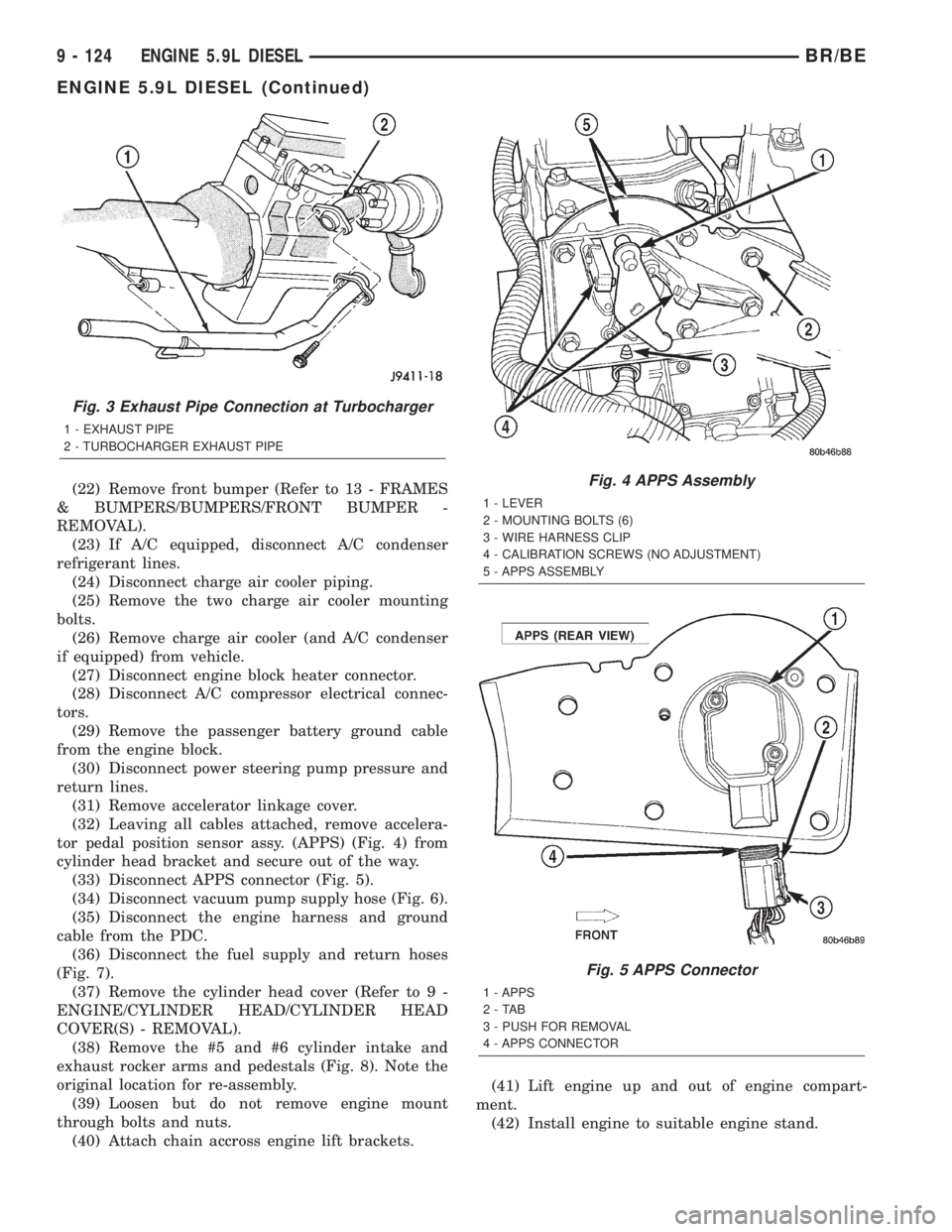
tor pedal position sensor assy. (APPS) (Fig. 4) from
cylinder head bracket and secure out of the way.
(33) Disconnect APPS connector (Fig. 5).
(34) Disconnect vacuum pump supply hose (Fig. 6).
(35) Disconnect the engine harness and ground
cable from the PDC.
(36) Disconnect the fuel supply and return hoses
(Fig. 7).
(37) Remove the cylinder head cover (Refer to 9 -
ENGINE/CYLINDER HEAD/CYLINDER HEAD
COVER(S) - REMOVAL).
(38) Remove the #5 and #6 cylinder intake and
exhaust rocker arms and pedestals (Fig. 8). Note the
original location for re-assembly.
(39) Loosen but do not remove engine mount
through bolts and nuts.
(40) Attach chain accross engine lift brackets.(41) Lift engine up and out of engine compart-
ment.
(42) Install engine to suitable engine stand.
Fig. 3 Exhaust Pipe Connection at Turbocharger
1 - EXHAUST PIPE
2 - TURBOCHARGER EXHAUST PIPE
Fig. 4 APPS Assembly
1 - LEVER
2 - MOUNTING BOLTS (6)
3 - WIRE HARNESS CLIP
4 - CALIBRATION SCREWS (NO ADJUSTMENT)
5 - APPS ASSEMBLY
Fig. 5 APPS Connector
1 - APPS
2-TAB
3 - PUSH FOR REMOVAL
4 - APPS CONNECTOR
9 - 124 ENGINE 5.9L DIESELBR/BE
ENGINE 5.9L DIESEL (Continued)
Page 1206 of 2255
(9) Disconnect turbocharger oil supply line at the
turbocharger end. Cap off open ports to prevent
intrusion of dirt or foreign material.
(10) Remove exhaust manifold-to-cylinder head
bolts and spacers. Remove exhaust manifold and tur-
bocharger from the vehicle as an assembly.
(11) Remove accessory drive belt (Refer to 7 -
COOLING/ACCESSORY DRIVE/DRIVE BELTS -
REMOVAL).
(12) Remove generator upper bracket.
(13) Disconnect radiator upper hose from the ther-
mostat housing.
(14) Disconnect the coolant temperature sensor
connector.
(15) Remove the engine harness to cylinder head
attaching bolt at front of head.
(16) Remove the engine harness ground fastener
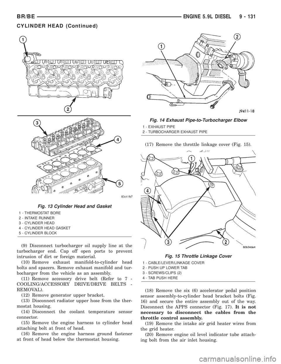
at front of head below the thermostat housing.(17) Remove the throttle linkage cover (Fig. 15).
(18) Remove the six (6) accelerator pedal position
sensor assembly-to-cylinder head bracket bolts (Fig.
16) and secure the entire assembly out of the way.
Disconnect the APPS connector (Fig. 17).It is not
necessary to disconnect the cables from the
throttle control assembly.
(19) Remove the intake air grid heater wires from
the grid heater.
(20) Remove engine oil level indicator tube attach-
ing bolt from the air inlet housing.
Fig. 13 Cylinder Head and Gasket
1 - THERMOSTAT BORE
2 - INTAKE RUNNER
3 - CYLINDER HEAD
4 - CYLINDER HEAD GASKET
5 - CYLINDER BLOCK
Fig. 14 Exhaust Pipe-to-Turbocharger Elbow
1 - EXHAUST PIPE
2 - TURBOCHARGER EXHAUST PIPE
Fig. 15 Throttle Linkage Cover
1 - CABLE/LEVER/LINKAGE COVER
2 - PUSH UP LOWER TAB
3 - SCREWS/CLIPS (2)
4 - TAB PUSH HERE
BR/BEENGINE 5.9L DIESEL 9 - 131
CYLINDER HEAD (Continued)
Page 1208 of 2255
(e) Loosen the #3, 5, and 6 cylinder high pres-
sure lines at the injection pump.
(f) Loosen the #3, 5, and 6 cylinder high pres-
sure lines at the cylinder head.
(g) Remove the #3, 5, and 6 cylinder high pres-
sure line bundle from the engine.
(25) Remove the lift pump-to-fuel filter low pres-
sure line.
(26) Remove the fuel filter-to-injection pump low
pressure line.
(27) Disconnect the water-in-fuel and fuel heater
connectors.
(28) Remove the fuel filter assembly-to-manifold
cover bolts and remove filter assembly from vehicle.
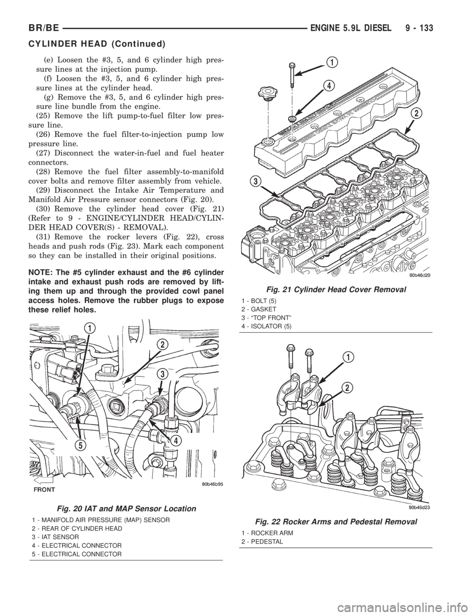
(29) Disconnect the Intake Air Temperature and
Manifold Air Pressure sensor connectors (Fig. 20).
(30) Remove the cylinder head cover (Fig. 21)
(Refer to 9 - ENGINE/CYLINDER HEAD/CYLIN-
DER HEAD COVER(S) - REMOVAL).
(31) Remove the rocker levers (Fig. 22), cross
heads and push rods (Fig. 23). Mark each component
so they can be installed in their original positions.
NOTE: The #5 cylinder exhaust and the #6 cylinder
intake and exhaust push rods are removed by lift-
ing them up and through the provided cowl panel
access holes. Remove the rubber plugs to expose
these relief holes.
Fig. 20 IAT and MAP Sensor Location
1 - MANIFOLD AIR PRESSURE (MAP) SENSOR
2 - REAR OF CYLINDER HEAD
3 - IAT SENSOR
4 - ELECTRICAL CONNECTOR
5 - ELECTRICAL CONNECTOR
Fig. 21 Cylinder Head Cover Removal
1 - BOLT (5)
2 - GASKET
3 - ªTOP FRONTº
4 - ISOLATOR (5)
Fig. 22 Rocker Arms and Pedestal Removal
1 - ROCKER ARM
2 - PEDESTAL
BR/BEENGINE 5.9L DIESEL 9 - 133
CYLINDER HEAD (Continued)
Page 1211 of 2255
INSTALLATION
WARNING: THE OUTSIDE EDGE OF THE HEAD
GASKET IS VERY SHARP. WHEN HANDLING THE
NEW HEAD GASKET, USE CARE NOT TO INJURE
YOURSELF.
(1) Install a new gasket with the part number side
up, and locate the gasket over the dowel sleeves.
(2) Using an engine lifting crane, lower the cylin-
der head onto the engine.
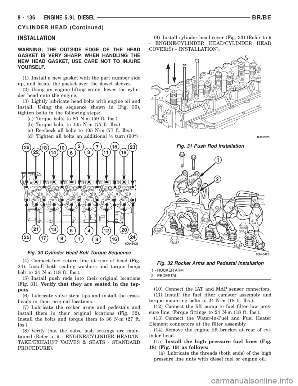
(3) Lightly lubricate head bolts with engine oil and
install. Using the sequence shown in (Fig. 30),
tighten bolts in the following steps:
(a) Torque bolts to 80 N´m (59 ft. lbs.)
(b) Torque bolts to 105 N´m (77 ft. lbs.)
(c) Re-check all bolts to 105 N´m (77 ft. lbs.)
(d) Tighten all bolts an additional ò turn (90É)
(4) Connect fuel return line at rear of head (Fig.
24). Install both sealing washers and torque banjo
bolt to 24 N´m (18 ft. lbs.).
(5) Install push rods into their original locations
(Fig. 31).Verify that they are seated in the tap-
pets.
(6) Lubricate valve stem tips and install the cross-
heads in their original locations.
(7) Lubricate the rocker arms and pedestals and
install them in their original locations (Fig. 32).
Install the bolts and torque them to 36 N´m (27 ft.
lbs.).
(8) Verify that the valve lash settings are main-
tained (Refer to 9 - ENGINE/CYLINDER HEAD/IN-
TAKE/EXHAUST VALVES & SEATS - STANDARD
PROCEDURE).(9) Install cylinder head cover (Fig. 33) (Refer to 9
- ENGINE/CYLINDER HEAD/CYLINDER HEAD
COVER(S) - INSTALLATION).
(10) Connect the IAT and MAP sensor connectors.
(11) Install the fuel filter canister assembly and
torque mounting bolts to 24 N´m (18 ft. lbs.).
(12) Connect the lift pump to fuel filter low pres-
sure line. Torque fittings to 24 N´m (18 ft. lbs.).
(13) Connect the Water-in-Fuel and Fuel Heater
Element connectors at the filter assembly.
(14) Remove the engine lift bracket at rear of cyl-
inder head.
(15)Install the high pressure fuel lines (Fig.
18) (Fig. 19) as follows:
(a) Lubricate the threads (both ends) of the high
pressure line nuts with diesel fuel or engine oil.
Fig. 30 Cylinder Head Bolt Torque Sequence
Fig. 31 Push Rod Installation
Fig. 32 Rocker Arms and Pedestal Installation
1 - ROCKER ARM
2 - PEDESTAL
9 - 136 ENGINE 5.9L DIESELBR/BE
CYLINDER HEAD (Continued)