Page 1624 of 2255
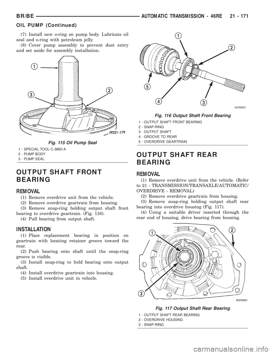
(7) Install new o-ring on pump body. Lubricate oil
seal and o-ring with petroleum jelly.
(8) Cover pump assembly to prevent dust entry
and set aside for assembly installation.
OUTPUT SHAFT FRONT
BEARING
REMOVAL
(1) Remove overdrive unit from the vehicle.
(2) Remove overdrive geartrain from housing.
(3) Remove snap-ring holding output shaft front
bearing to overdrive geartrain. (Fig. 116).
(4) Pull bearing from output shaft.
INSTALLATION
(1) Place replacement bearing in position on
geartrain with locating retainer groove toward the
rear.
(2) Push bearing onto shaft until the snap-ring
groove is visible.
(3) Install snap-ring to hold bearing onto output
shaft.
(4) Install overdrive geartrain into housing.
(5) Install overdrive unit in vehicle.
OUTPUT SHAFT REAR
BEARING
REMOVAL
(1) Remove overdrive unit from the vehicle. (Refer
to 21 - TRANSMISSION/TRANSAXLE/AUTOMATIC/
OVERDRIVE - REMOVAL)
(2) Remove overdrive geartrain from housing.
(3) Remove snap-ring holding output shaft rear
bearing into overdrive housing (Fig. 117).
(4) Using a suitable driver inserted through the
rear end of housing, drive bearing from housing.
Fig. 115 Oil Pump Seal
1 - SPECIAL TOOL C-3860-A
2 - PUMP BODY
3 - PUMP SEAL
Fig. 116 Output Shaft Front Bearing
1 - OUTPUT SHAFT FRONT BEARING
2 - SNAP-RING
3 - OUTPUT SHAFT
4 - GROOVE TO REAR
5 - OVERDRIVE GEARTRAIN
Fig. 117 Output Shaft Rear Bearing
1 - OUTPUT SHAFT REAR BEARING
2 - OVERDRIVE HOUSING
3 - SNAP-RING
BR/BEAUTOMATIC TRANSMISSION - 46RE 21 - 171
OIL PUMP (Continued)
Page 1625 of 2255
INSTALLATION
(1) Place replacement bearing in position in hous-
ing.
(2) Using a suitable driver, drive bearing into
housing until the snap-ring groove is visible.
(3) Install snap-ring to hold bearing into housing
(Fig. 117).
(4) Install overdrive geartrain into housing.
(5) Install overdrive unit in vehicle.
OVERDRIVE CLUTCH
DESCRIPTION
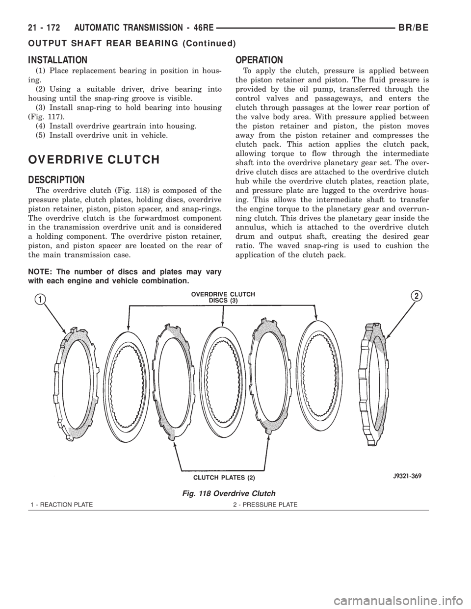
The overdrive clutch (Fig. 118) is composed of the
pressure plate, clutch plates, holding discs, overdrive
piston retainer, piston, piston spacer, and snap-rings.
The overdrive clutch is the forwardmost component
in the transmission overdrive unit and is considered
a holding component. The overdrive piston retainer,
piston, and piston spacer are located on the rear of
the main transmission case.
NOTE: The number of discs and plates may vary
with each engine and vehicle combination.
OPERATION
To apply the clutch, pressure is applied between
the piston retainer and piston. The fluid pressure is
provided by the oil pump, transferred through the
control valves and passageways, and enters the
clutch through passages at the lower rear portion of
the valve body area. With pressure applied between
the piston retainer and piston, the piston moves
away from the piston retainer and compresses the
clutch pack. This action applies the clutch pack,
allowing torque to flow through the intermediate
shaft into the overdrive planetary gear set. The over-
drive clutch discs are attached to the overdrive clutch
hub while the overdrive clutch plates, reaction plate,
and pressure plate are lugged to the overdrive hous-
ing. This allows the intermediate shaft to transfer
the engine torque to the planetary gear and overrun-
ning clutch. This drives the planetary gear inside the
annulus, which is attached to the overdrive clutch
drum and output shaft, creating the desired gear
ratio. The waved snap-ring is used to cushion the
application of the clutch pack.
Fig. 118 Overdrive Clutch
1 - REACTION PLATE 2 - PRESSURE PLATE
21 - 172 AUTOMATIC TRANSMISSION - 46REBR/BE
OUTPUT SHAFT REAR BEARING (Continued)
Page 1626 of 2255
OVERDRIVE UNIT
REMOVAL
(1) Shift transmission into PARK.
(2) Raise vehicle.
(3) Remove transfer case, if equipped.
(4) Mark propeller shaft universal joint(s) and axle
pinion yoke, or the companion flange and flange
yoke, for alignment reference at installation, if necc-
esary.
(5) Disconnect and remove the rear propeller shaft,
if necessary. (Refer to 3 - DIFFERENTIAL & DRIV-
ELINE/PROPELLER SHAFT/PROPELLER SHAFT -
REMOVAL)
(6) Remove transmission oil pan, remove gasket,
drain oil and reinstall pan.
(7) If overdrive unit had malfunctioned, or if fluid
is contaminated, remove entire transmission. If diag-
nosis indicated overdrive problems only, remove just
the overdrive unit.
(8) Support transmission with transmission jack.
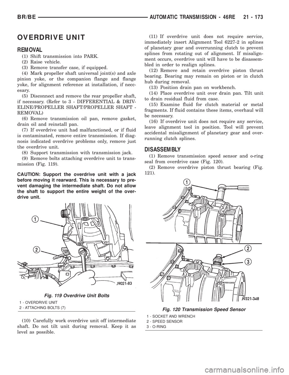
(9) Remove bolts attaching overdrive unit to trans-
mission (Fig. 119).
CAUTION: Support the overdrive unit with a jack
before moving it rearward. This is necessary to pre-
vent damaging the intermediate shaft. Do not allow
the shaft to support the entire weight of the over-
drive unit.
(10) Carefully work overdrive unit off intermediate
shaft. Do not tilt unit during removal. Keep it as
level as possible.(11) If overdrive unit does not require service,
immediately insert Alignment Tool 6227-2 in splines
of planetary gear and overrunning clutch to prevent
splines from rotating out of alignment. If misalign-
ment occurs, overdrive unit will have to be disassem-
bled in order to realign splines.
(12) Remove and retain overdrive piston thrust
bearing. Bearing may remain on piston or in clutch
hub during removal.
(13) Position drain pan on workbench.
(14) Place overdrive unit over drain pan. Tilt unit
to drain residual fluid from case.
(15) Examine fluid for clutch material or metal
fragments. If fluid contains these items, overhaul will
be necessary.
(16) If overdrive unit does not require any service,
leave alignment tool in position. Tool will prevent
accidental misalignment of planetary gear and over-
running clutch splines.
DISASSEMBLY
(1) Remove transmission speed sensor and o-ring
seal from overdrive case (Fig. 120).
(2) Remove overdrive piston thrust bearing (Fig.
121).
Fig. 119 Overdrive Unit Bolts
1 - OVERDRIVE UNIT
2 - ATTACHING BOLTS (7)
Fig. 120 Transmission Speed Sensor
1 - SOCKET AND WRENCH
2 - SPEED SENSOR
3 - O-RING
BR/BEAUTOMATIC TRANSMISSION - 46RE 21 - 173
Page 1627 of 2255
OVERDRIVE PISTON
(1) Remove overdrive piston thrust plate (Fig.
122). Retain thrust plate. It is a select fit part and
may possibly be reused.(2) Remove intermediate shaft spacer (Fig. 123).
Retain spacer. It is a select fit part and may possibly
be reused.
(3) Remove overdrive piston from retainer (Fig.
124).
Fig. 121 Overdrive Piston Thrust Bearing Removal/
Installation
1 - THRUST BEARING
2 - OVERDRIVE PISTON
3 - THRUST PLATE
Fig. 122 Overdrive Piston Thrust Plate Removal/
Installation
1 - OVERDRIVE PISTON
2 - OVERDRIVE PISTON SPACER (SELECT FIT)
Fig. 123 Intermediate Shaft Spacer Location
1 - INTERMEDIATE SHAFT
2 - INTERMEDIATE SHAFT SPACER (SELECT FIT)
Fig. 124 Overdrive Piston Removal
1 - PISTON RETAINER
2 - OVERDRIVE PISTON
21 - 174 AUTOMATIC TRANSMISSION - 46REBR/BE
OVERDRIVE UNIT (Continued)
Page 1628 of 2255
OVERDRIVE CLUTCH PACK
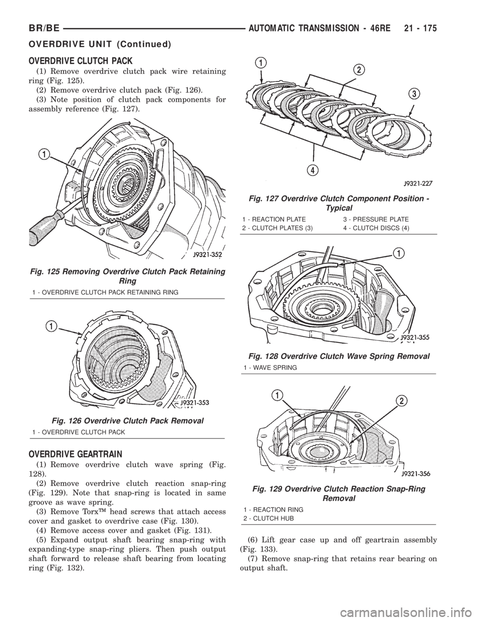
(1) Remove overdrive clutch pack wire retaining
ring (Fig. 125).
(2) Remove overdrive clutch pack (Fig. 126).
(3) Note position of clutch pack components for
assembly reference (Fig. 127).
OVERDRIVE GEARTRAIN
(1) Remove overdrive clutch wave spring (Fig.
128).
(2) Remove overdrive clutch reaction snap-ring
(Fig. 129). Note that snap-ring is located in same
groove as wave spring.
(3) Remove TorxŸ head screws that attach access
cover and gasket to overdrive case (Fig. 130).
(4) Remove access cover and gasket (Fig. 131).
(5) Expand output shaft bearing snap-ring with
expanding-type snap-ring pliers. Then push output
shaft forward to release shaft bearing from locating
ring (Fig. 132).(6) Lift gear case up and off geartrain assembly
(Fig. 133).
(7) Remove snap-ring that retains rear bearing on
output shaft.
Fig. 125 Removing Overdrive Clutch Pack Retaining
Ring
1 - OVERDRIVE CLUTCH PACK RETAINING RING
Fig. 126 Overdrive Clutch Pack Removal
1 - OVERDRIVE CLUTCH PACK
Fig. 127 Overdrive Clutch Component Position -
Typical
1 - REACTION PLATE 3 - PRESSURE PLATE
2 - CLUTCH PLATES (3) 4 - CLUTCH DISCS (4)
Fig. 128 Overdrive Clutch Wave Spring Removal
1 - WAVE SPRING
Fig. 129 Overdrive Clutch Reaction Snap-Ring
Removal
1 - REACTION RING
2 - CLUTCH HUB
BR/BEAUTOMATIC TRANSMISSION - 46RE 21 - 175
OVERDRIVE UNIT (Continued)
Page 1629 of 2255
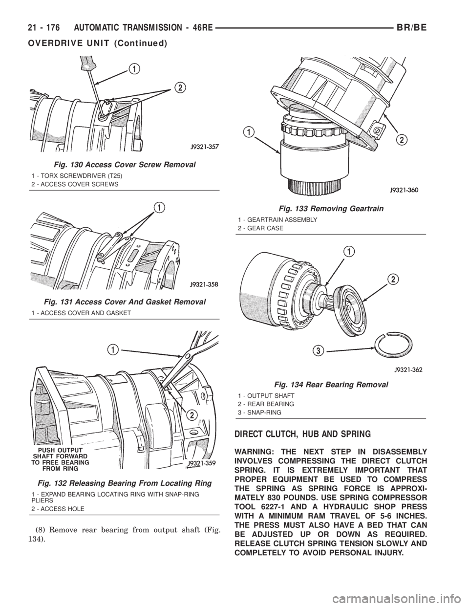
(8) Remove rear bearing from output shaft (Fig.
134).
DIRECT CLUTCH, HUB AND SPRING
WARNING: THE NEXT STEP IN DISASSEMBLY
INVOLVES COMPRESSING THE DIRECT CLUTCH
SPRING. IT IS EXTREMELY IMPORTANT THAT
PROPER EQUIPMENT BE USED TO COMPRESS
THE SPRING AS SPRING FORCE IS APPROXI-
MATELY 830 POUNDS. USE SPRING COMPRESSOR
TOOL 6227-1 AND A HYDRAULIC SHOP PRESS
WITH A MINIMUM RAM TRAVEL OF 5-6 INCHES.
THE PRESS MUST ALSO HAVE A BED THAT CAN
BE ADJUSTED UP OR DOWN AS REQUIRED.
RELEASE CLUTCH SPRING TENSION SLOWLY AND
COMPLETELY TO AVOID PERSONAL INJURY.
Fig. 130 Access Cover Screw Removal
1 - TORX SCREWDRIVER (T25)
2 - ACCESS COVER SCREWS
Fig. 131 Access Cover And Gasket Removal
1 - ACCESS COVER AND GASKET
Fig. 132 Releasing Bearing From Locating Ring
1 - EXPAND BEARING LOCATING RING WITH SNAP-RING
PLIERS
2 - ACCESS HOLE
Fig. 133 Removing Geartrain
1 - GEARTRAIN ASSEMBLY
2 - GEAR CASE
Fig. 134 Rear Bearing Removal
1 - OUTPUT SHAFT
2 - REAR BEARING
3 - SNAP-RING
21 - 176 AUTOMATIC TRANSMISSION - 46REBR/BE
OVERDRIVE UNIT (Continued)
Page 1630 of 2255
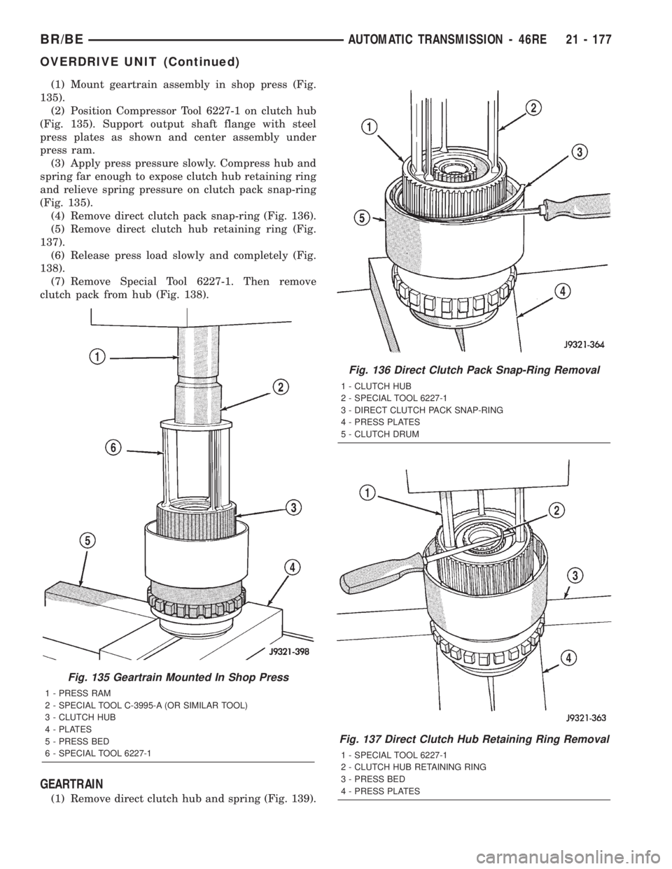
(1) Mount geartrain assembly in shop press (Fig.
135).
(2) Position Compressor Tool 6227-1 on clutch hub
(Fig. 135). Support output shaft flange with steel
press plates as shown and center assembly under
press ram.
(3) Apply press pressure slowly. Compress hub and
spring far enough to expose clutch hub retaining ring
and relieve spring pressure on clutch pack snap-ring
(Fig. 135).
(4) Remove direct clutch pack snap-ring (Fig. 136).
(5) Remove direct clutch hub retaining ring (Fig.
137).
(6) Release press load slowly and completely (Fig.
138).
(7) Remove Special Tool 6227-1. Then remove
clutch pack from hub (Fig. 138).
GEARTRAIN
(1) Remove direct clutch hub and spring (Fig. 139).
Fig. 135 Geartrain Mounted In Shop Press
1 - PRESS RAM
2 - SPECIAL TOOL C-3995-A (OR SIMILAR TOOL)
3 - CLUTCH HUB
4 - PLATES
5 - PRESS BED
6 - SPECIAL TOOL 6227-1
Fig. 136 Direct Clutch Pack Snap-Ring Removal
1 - CLUTCH HUB
2 - SPECIAL TOOL 6227-1
3 - DIRECT CLUTCH PACK SNAP-RING
4 - PRESS PLATES
5 - CLUTCH DRUM
Fig. 137 Direct Clutch Hub Retaining Ring Removal
1 - SPECIAL TOOL 6227-1
2 - CLUTCH HUB RETAINING RING
3 - PRESS BED
4 - PRESS PLATES
BR/BEAUTOMATIC TRANSMISSION - 46RE 21 - 177
OVERDRIVE UNIT (Continued)
Page 1631 of 2255
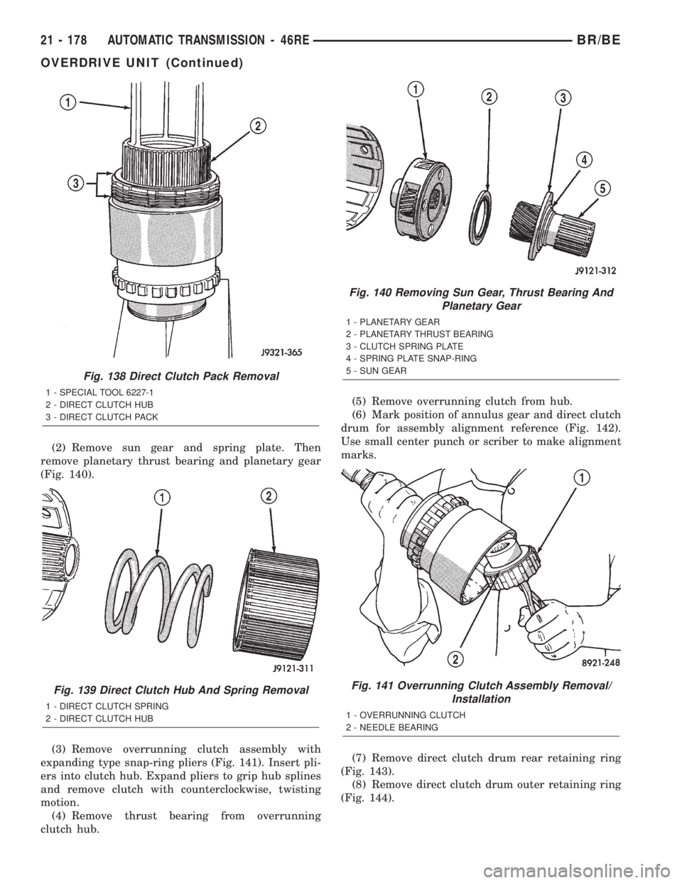
(2) Remove sun gear and spring plate. Then
remove planetary thrust bearing and planetary gear
(Fig. 140).
(3) Remove overrunning clutch assembly with
expanding type snap-ring pliers (Fig. 141). Insert pli-
ers into clutch hub. Expand pliers to grip hub splines
and remove clutch with counterclockwise, twisting
motion.
(4) Remove thrust bearing from overrunning
clutch hub.(5) Remove overrunning clutch from hub.
(6) Mark position of annulus gear and direct clutch
drum for assembly alignment reference (Fig. 142).
Use small center punch or scriber to make alignment
marks.
(7) Remove direct clutch drum rear retaining ring
(Fig. 143).
(8) Remove direct clutch drum outer retaining ring
(Fig. 144).
Fig. 138 Direct Clutch Pack Removal
1 - SPECIAL TOOL 6227-1
2 - DIRECT CLUTCH HUB
3 - DIRECT CLUTCH PACK
Fig. 139 Direct Clutch Hub And Spring Removal
1 - DIRECT CLUTCH SPRING
2 - DIRECT CLUTCH HUB
Fig. 140 Removing Sun Gear, Thrust Bearing And
Planetary Gear
1 - PLANETARY GEAR
2 - PLANETARY THRUST BEARING
3 - CLUTCH SPRING PLATE
4 - SPRING PLATE SNAP-RING
5 - SUN GEAR
Fig. 141 Overrunning Clutch Assembly Removal/
Installation
1 - OVERRUNNING CLUTCH
2 - NEEDLE BEARING
21 - 178 AUTOMATIC TRANSMISSION - 46REBR/BE
OVERDRIVE UNIT (Continued)