2002 DODGE RAM wheel bolt torque
[x] Cancel search: wheel bolt torquePage 154 of 2255
(13) Install the fill hole plug and tighten to 34 N´m
(25 ft. lbs.).
(14) Remove support and lower vehicle.
DIFFERENTIAL - POWR-LOK
DIAGNOSIS AND TESTING - POWR-LOKT
WARNING: WHEN SERVICING VEHICLES WITH A
POWR-LOKTDIFFERENTIAL DO NOT USE THE
ENGINE TO TURN THE AXLE AND WHEELS. BOTH
REAR WHEELS MUST BE RAISED AND THE VEHI-
CLE SUPPORTED. THE AXLE CAN EXERT ENOUGH
FORCE IF ONE WHEEL IS IN CONTACT WITH A
SURFACE TO CAUSE THE VEHICLE TO MOVE.
The differential can be tested without removing the
differential case by measuring rotating torque. Make
sure brakes are not dragging during this measure-
ment.
(1) Place blocks in front and rear of both front
wheels.
(2) Raise one rear wheel until it is completely off
the ground.
(3) Engine off, transmission in neutral, and park-
ing brake off.
(4) Remove wheel and bolt Special Tool 6790 or
equivalent to wheel studs.(5) Use torque wrench on special tool to rotate
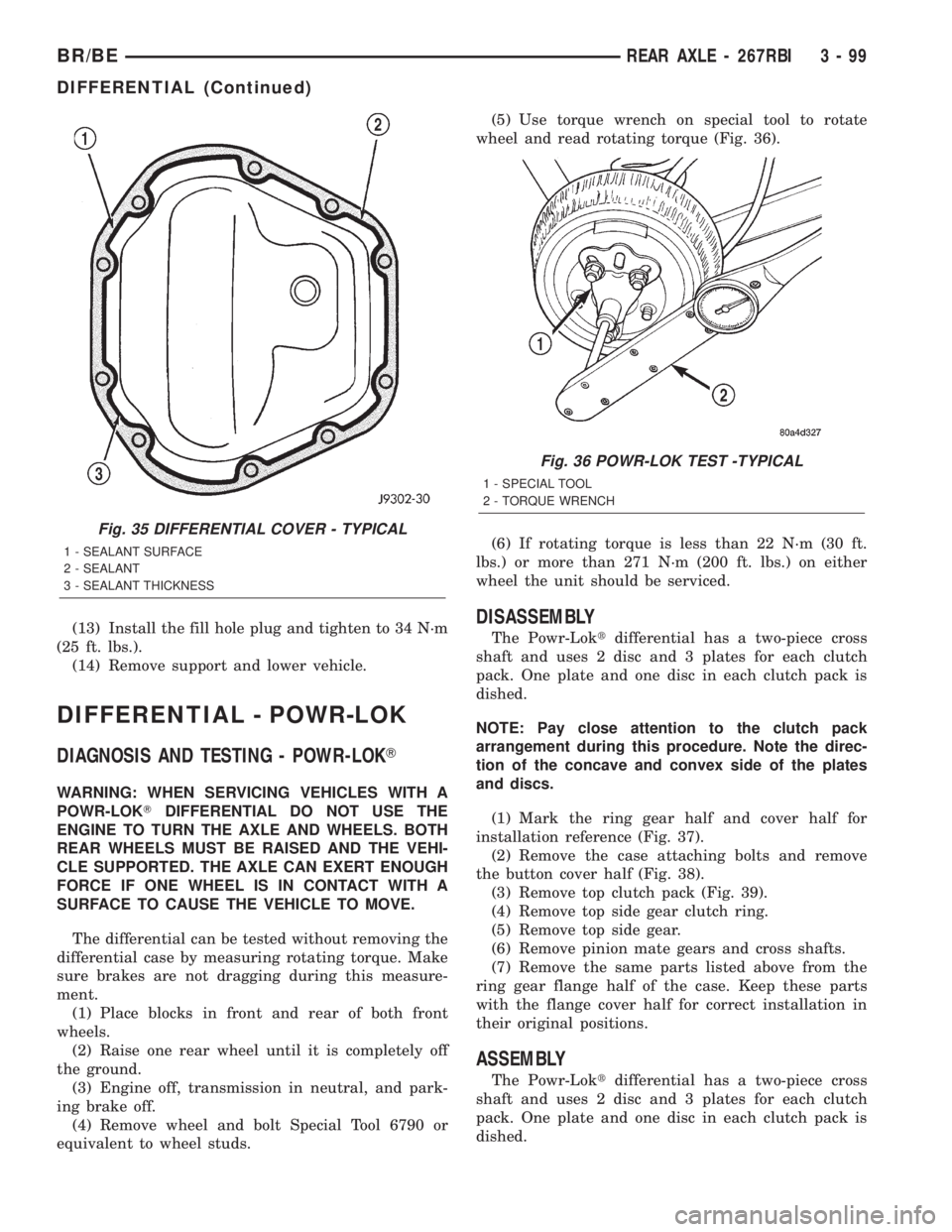
wheel and read rotating torque (Fig. 36).
(6) If rotating torque is less than 22 N´m (30 ft.
lbs.) or more than 271 N´m (200 ft. lbs.) on either
wheel the unit should be serviced.
DISASSEMBLY
The Powr-Loktdifferential has a two-piece cross
shaft and uses 2 disc and 3 plates for each clutch
pack. One plate and one disc in each clutch pack is
dished.
NOTE: Pay close attention to the clutch pack
arrangement during this procedure. Note the direc-
tion of the concave and convex side of the plates
and discs.
(1) Mark the ring gear half and cover half for
installation reference (Fig. 37).
(2) Remove the case attaching bolts and remove
the button cover half (Fig. 38).
(3) Remove top clutch pack (Fig. 39).
(4) Remove top side gear clutch ring.
(5) Remove top side gear.
(6) Remove pinion mate gears and cross shafts.
(7) Remove the same parts listed above from the
ring gear flange half of the case. Keep these parts
with the flange cover half for correct installation in
their original positions.
ASSEMBLY
The Powr-Loktdifferential has a two-piece cross
shaft and uses 2 disc and 3 plates for each clutch
pack. One plate and one disc in each clutch pack is
dished.
Fig. 35 DIFFERENTIAL COVER - TYPICAL
1 - SEALANT SURFACE
2 - SEALANT
3 - SEALANT THICKNESS
Fig. 36 POWR-LOK TEST -TYPICAL
1 - SPECIAL TOOL
2 - TORQUE WRENCH
BR/BEREAR AXLE - 267RBI 3 - 99
DIFFERENTIAL (Continued)
Page 162 of 2255

REAR AXLE - 286RBI
TABLE OF CONTENTS
page page
REAR AXLE - 286RBI
DESCRIPTION........................107
OPERATION..........................108
DIAGNOSIS AND TESTING - AXLE.........108
REMOVAL............................112
INSTALLATION........................112
ADJUSTMENTS.......................112
SPECIFICATIONS
REAR AXLE - 286RBI.................120
SPECIAL TOOLS
REAR AXLE - 286 RBI.................120
AXLE SHAFTS
REMOVAL............................123
INSTALLATION........................123
AXLE BEARINGS
REMOVAL............................123
INSTALLATION........................123
PINION SEAL
REMOVAL............................123INSTALLATION........................124
DIFFERENTIAL
REMOVAL............................125
DISASSEMBLY........................126
ASSEMBLY...........................126
INSTALLATION........................126
DIFFERENTIAL - TRAC-LOK
DIAGNOSIS AND TESTING - TRAC-LOKT....128
DISASSEMBLY........................128
ASSEMBLY...........................129
DIFFERENTIAL CASE BEARINGS
REMOVAL............................129
INSTALLATION........................129
PINION GEAR/RING GEAR/TONE RING
REMOVAL............................131
INSTALLATION........................132
REAR AXLE - 286RBI
DESCRIPTION
The Rear Beam-design Iron (RBI) axle housings
consist of an iron center casting (differential housing)
with axle shaft tubes extending from either side. The
tubes are pressed into the differential housing and
welded. The axles are full-floating axle shafts, that
are supported by the axle housing tubes. The full-
float axle shafts are retained by bolts attached to the
hub.
The differential case for the standard differential is
a one-piece design. Differential bearing preload and
ring gear backlash are adjusted by the use of shims
located between the differential bearing cones andcase. Outboard protective spacers are located
between the differential bearing cup and housing.
Pinion bearing preload is set and maintained by the
use of shims. Pinion height is controlled by a shim
pack located under the inner pinion bearing cup. The
differential cover provides a means for inspection and
service.
Axles equipped with a Trac-Loktdifferential are
optional. The differential contains two clutch packs,
four pinion gears, and a one-piece pinion mate cross
shaft to provide increased torque to the non-slipping
wheel in addition to the standard differential compo-
nents. A Trac-loktdifferential for the has a two-piece
differential case.
BR/BEREAR AXLE - 286RBI 3 - 107
Page 163 of 2255

OPERATION
STANDARD DIFFERENTIAL
The axle receives power from the transmission/
transfer case through the rear propeller shaft. The
rear propeller shaft is connected to the pinion gear
which rotates the differential through the gear mesh
with the ring gear bolted to the differential case. The
engine power is transmitted to the axle shafts
through the pinion mate and side gears. The side
gears are splined to the axle shafts.
During straight-ahead driving, the differential pin-
ion gears do not rotate on the pinion mate shaft. This
occurs because input torque applied to the gears is
divided and distributed equally between the two side
gears. As a result, the pinion gears revolve with the
pinion mate shaft but do not rotate around it (Fig. 1).
When turning corners, the outside wheel must travel
a greater distance than the inside wheel to complete a
turn. The difference must be compensated for to prevent
the tires from scuffing and skidding through turns. To
accomplish this, the differential allows the axle shafts
to turn at unequal speeds (Fig. 2). In this instance, the
input torque applied to the pinion gears is not divided
equally. The pinion gears now rotate around the pinion
mate shaft in opposite directions. This allows the side
gear and axle shaft attached to the outside wheel to
rotate at a faster speed.
TRAC-LOKŸ DIFFERENTIAL
The Trac-lokŸ clutches are engaged by two concur-
rent forces. The first being the preload force exerted
through Belleville spring washers within the clutch
packs. The second is the separating forces generatedby the side gears as torque is applied through the
ring gear (Fig. 3).
The Trac-lokŸ design provides the differential
action needed for turning corners and for driving
straight ahead during periods of unequal traction.
When one wheel looses traction, the clutch packs
transfer additional torque to the wheel having the
most traction. Trac-lokŸ differentials resist wheel
spin on bumpy roads and provide more pulling power
when one wheel looses traction. Pulling power is pro-
vided continuously until both wheels loose traction. If
both wheels slip due to unequal traction, Trac-lokŸ
operation is normal. In extreme cases of differences
of traction, the wheel with the least traction may
spin.
DIAGNOSIS AND TESTING - AXLE
GEAR NOISE
Axle gear noise can be caused by insufficient lubri-
cant, incorrect backlash, incorrect pinion depth, tooth
contact, worn/damaged gears, or the carrier housing
not having the proper offset and squareness.
Gear noise usually happens at a specific speed
range. The noise can also occur during a specific type
of driving condition. These conditions are accelera-
tion, deceleration, coast, or constant load.
When road testing, first warm-up the axle fluid by
driving the vehicle at least 5 miles and then acceler-
ate the vehicle to the speed range where the noise is
the greatest. Shift out-of-gear and coast through the
peak-noise range. If the noise stops or changes
greatly:
²Check for insufficient lubricant.
²Incorrect ring gear backlash.
²Gear damage.
Differential side gears and pinions can be checked
by turning the vehicle. They usually do not cause
Fig. 1 STRAIGHT AHEAD DRIVING
1 - IN STRAIGHT AHEAD DRIVING EACH WHEEL ROTATES AT
100% OF CASE SPEED
2 - PINION GEAR
3 - SIDE GEAR
4 - PINION GEARS ROTATE WITH CASE
Fig. 2 ON TURNS
1 - PINION GEARS ROTATE ON PINION SHAFT
3 - 108 REAR AXLE - 286RBIBR/BE
REAR AXLE - 286RBI (Continued)
Page 178 of 2255
AXLE SHAFTS
REMOVAL
(1) Remove the axle shaft flange bolts.
(2) Slide the axle shaft out from the axle tube.
INSTALLATION
(1) Clean the gasket contact surface area on the
flange with an appropriate solvent. Install a new
flange gasket and slide the axle shaft into the tube.
(2) Install the bolts and tighten to 129 N´m (95 ft.
lbs.).
AXLE BEARINGS
REMOVAL
(1) Remove wheel and tire assembly.
(2) Remove brake drum.
(3) Remove the axle shaft.
(4) Remove the lock wedge and adjustment nut.
Remove adjustment nut with Socket DD-1241-JD.
(5) Remove the hub assembly. The outer axle bear-
ing will slide out as the hub is being removed.
(6) Drive grease seal and inner bearing out of the
hub with Installer 5064 and Handle C-4171.
(7) Remove bearing cups from the hub with a
brass drift and a hammer.
INSTALLATION
(1) Thoroughly clean both axle bearings and inte-
rior of the hub with an appropriate cleaning solvent.
(2) Install bearing cups with Installer 8153 and
Handle C-4171.
(3) Pack inner and outer bearings with Mopar
wheel bearing grease or equivalent
(4) Apply lubricant to surface area of the bearing
cup.
(5) Install inner axle bearing in the hub.
(6) Install anewbearing grease seal with
Installer 8152 and Handle C-4171.
(7) Inspect bearing and seal contact surfaces on
the axle tube spindle for burrs and/or roughness.
Remove all the rough contact surfaces from the axle
spindle.
CAUTION: Do not let grease seal contact the axle
tube threads during installation.
(8) Carefully slide the hub onto the axle.
(9) Install outer axle bearing.
(10) Install hub bearing adjustment nut with
Socket DD-1241±JD.
(11) Tighten adjustment nut to 163-190 N´m (120-
140 ft. lbs.) while rotating the wheel.(12) Loosen adjustment nut 1/8 of-a-turn to pro-
vide 0.001-inch to 0.010-inch wheel bearing end play.
(13) Tap the locking wedge into the spindle key-
way and adjustment nut.
NOTE: Locate locking wedge in a new position in
the adjustment nut.
(14) Install axle shaft and brake drum.
(15) Install wheel and tire assembly.
PINION SEAL
REMOVAL
(1) Raise and support the vehicle.
(2) Mark the universal joint, pinion yoke, and pin-
ion shaft for installation reference.
(3) Disconnect the propeller shaft from the pinion
yoke. Secure the propeller shaft in an upright posi-
tion to prevent damage to the rear universal joint.
(4) Remove wheel and tire assemblies.
(5) Remove brake calipers to prevent any drag.
The drag may cause a false bearing preload torque
measurement.
(6) Rotate pinion yoke three or four times.
(7) Record the amount of torque necessary to
rotate the pinion gear with an inch pound dial-type
torque wrench.
(8) Hold the yoke with Holder 6719A and remove
the pinion shaft nut and washer.
(9) Remove yoke from the pinion with Remover
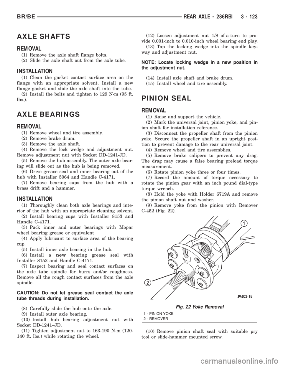
C-452 (Fig. 22).
(10) Remove pinion shaft seal with suitable pry
tool or slide-hammer mounted screw.
Fig. 22 Yoke Removal
1 - PINION YOKE
2 - REMOVER
BR/BEREAR AXLE - 286RBI 3 - 123
Page 183 of 2255
(12) Fill the differential with Mopar Hypoid Gear
Lubricant or equivalent to bottom of the fill plug
hole.
(13) Install fill hole plug and tighten to 34 N´m (25
ft. lbs.).
(14) Remove support and lower vehicle.
DIFFERENTIAL - TRAC-LOK
DIAGNOSIS AND TESTING - TRAC-LOKT
The most common problem is a chatter noise when
turning corners. Before removing a Trac-lokŸ unit
for repair, drain, flush and refill the axle with the
specified lubricant. A container of Mopar Trac-lokŸ
Lubricant (friction modifier) should be added after
repair service or during a lubricant change.
After changing the lubricant, drive the vehicle and
make 10 to 12 slow, figure-eight turns. This maneu-
ver will pump lubricant through the clutches. This
will correct the condition in most instances. If the
chatter persists, clutch damage could have occurred.
DIFFERENTIAL TEST
The differential can be tested without removing the
differential case by measuring rotating torque. Make
sure brakes are not dragging during this measure-
ment.
(1) Place blocks in front and rear of both front
wheels.
(2) Raise one rear wheel until it is completely off
the ground.
(3) Engine off, transmission in neutral, and park-
ing brake off.
(4) Remove wheel and bolt Special Tool 6790 or
equivalent tool to studs.
(5) Use torque wrench on special tool to rotate
wheel and read rotating torque.
(6) If rotating torque is less than 22 N´m (30 ft.
lbs.) or more than 271 N´m (200 ft. lbs.) on either
wheel the unit should be serviced.
DISASSEMBLY
The Trac-Loktdifferential on this axle has a one-
piece cross shaft and uses one dished disc, regular 5
disc and 7 plates.
NOTE: Pay attention to the clutch pack arrangement
during disassembly. Note the direction of the con-
cave and convex side of the plates and discs.
(1) Mark the ring gear half and cover half for
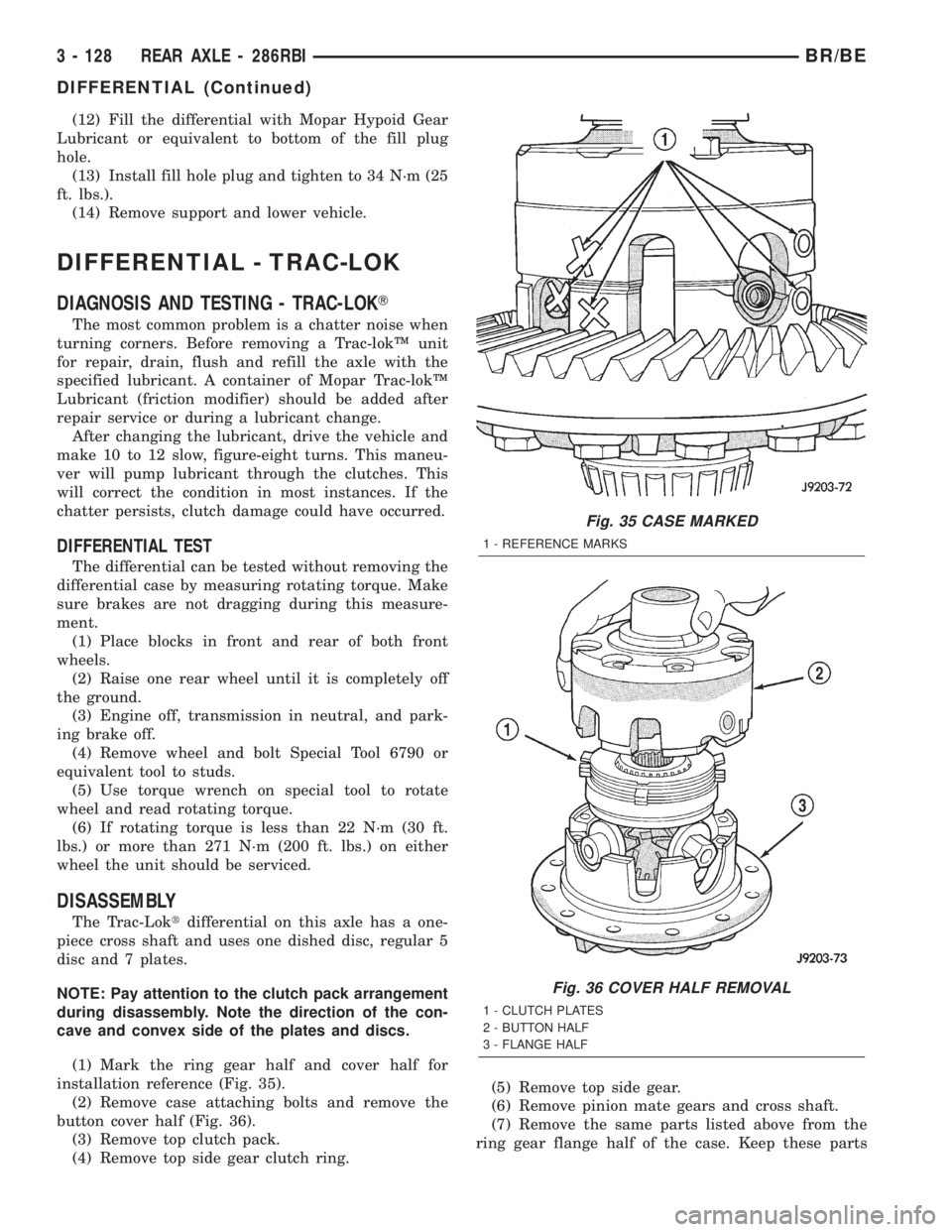
installation reference (Fig. 35).
(2) Remove case attaching bolts and remove the
button cover half (Fig. 36).
(3) Remove top clutch pack.
(4) Remove top side gear clutch ring.(5) Remove top side gear.
(6) Remove pinion mate gears and cross shaft.
(7) Remove the same parts listed above from the
ring gear flange half of the case. Keep these parts
Fig. 35 CASE MARKED
1 - REFERENCE MARKS
Fig. 36 COVER HALF REMOVAL
1 - CLUTCH PLATES
2 - BUTTON HALF
3 - FLANGE HALF
3 - 128 REAR AXLE - 286RBIBR/BE
DIFFERENTIAL (Continued)
Page 226 of 2255
HCU pump and solenoids. A second base brake bleed-
ing procedure is then required to remove any air
remaining in the system.
(1) Perform the base brake bleeding, (Refer to 5 -
BRAKES/HYDRAULIC/MECHANICAL - STAN-
DARD PROCEDURE).
(2) Connect the scan tool to the Data Link Connec-
tor.(3) Select ANTILOCK BRAKES, followed by MIS-
CELLANEOUS, then ABS BRAKES. Follow the
instructions displayed. When scan tool displays TEST
COMPLETE, disconnect scan tool and proceed.
(4) Perform base brake bleeding a second time,
(Refer to 5 - BRAKES/HYDRAULIC/MECHANICAL -
STANDARD PROCEDURE).
(5) Top off master cylinder fluid level and verify
proper brake operation before moving vehicle.
SPECIFICATIONS
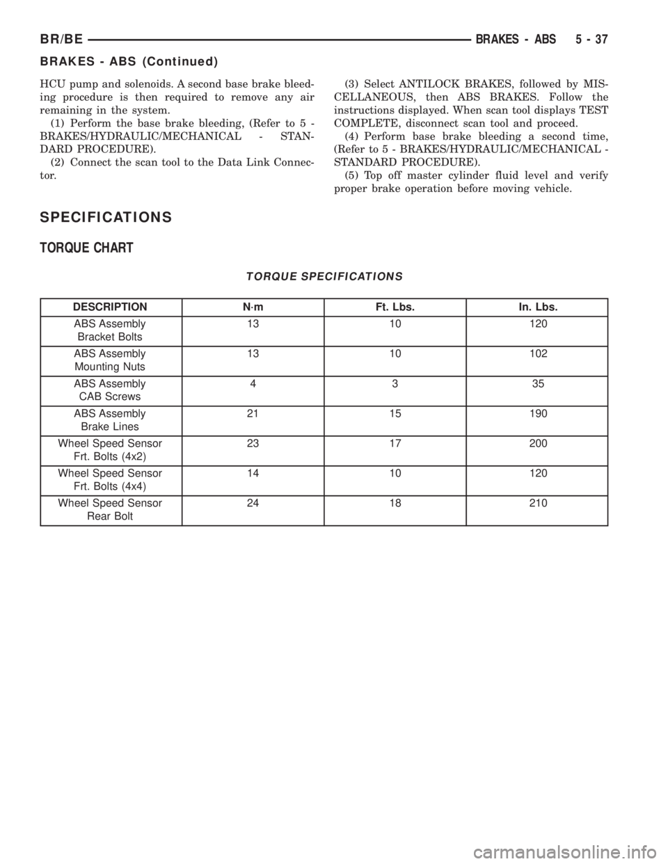
TORQUE CHART
TORQUE SPECIFICATIONS
DESCRIPTION N´m Ft. Lbs. In. Lbs.
ABS Assembly
Bracket Bolts13 10 120
ABS Assembly
Mounting Nuts13 10 102
ABS Assembly
CAB Screws4335
ABS Assembly
Brake Lines21 15 190
Wheel Speed Sensor
Frt. Bolts (4x2)23 17 200
Wheel Speed Sensor
Frt. Bolts (4x4)14 10 120
Wheel Speed Sensor
Rear Bolt24 18 210
BR/BEBRAKES - ABS 5 - 37
BRAKES - ABS (Continued)
Page 232 of 2255
CLUTCH
TABLE OF CONTENTS
page page
CLUTCH
DESCRIPTION..........................1
OPERATION............................2
WARNING.............................2
DIAGNOSIS AND TESTING - CLUTCH........2
SPECIFICATIONS - CLUTCH...............7
CLUTCH DISC
REMOVAL.............................7
INSTALLATION..........................8
CLUTCH HOUSING
DIAGNOSIS AND TESTING - CLUTCH
HOUSING............................9
REMOVAL.............................11
INSTALLATION.........................11
CLUTCH RELEASE BEARING
REMOVAL.............................12
INSTALLATION.........................12FLYWHEEL
DIAGNOSIS AND TESTING - FLYWHEEL.....13
DISASSEMBLY.........................13
ASSEMBLY............................14
PILOT BEARING
REMOVAL.............................14
INSTALLATION.........................14
CLUTCH PEDAL
REMOVAL.............................15
INSTALLATION.........................15
LINKAGE
REMOVAL.............................15
INSTALLATION.........................16
CLUTCH PEDAL POSITION SWITCH
DESCRIPTION.........................17
OPERATION...........................17
CLUTCH
DESCRIPTION
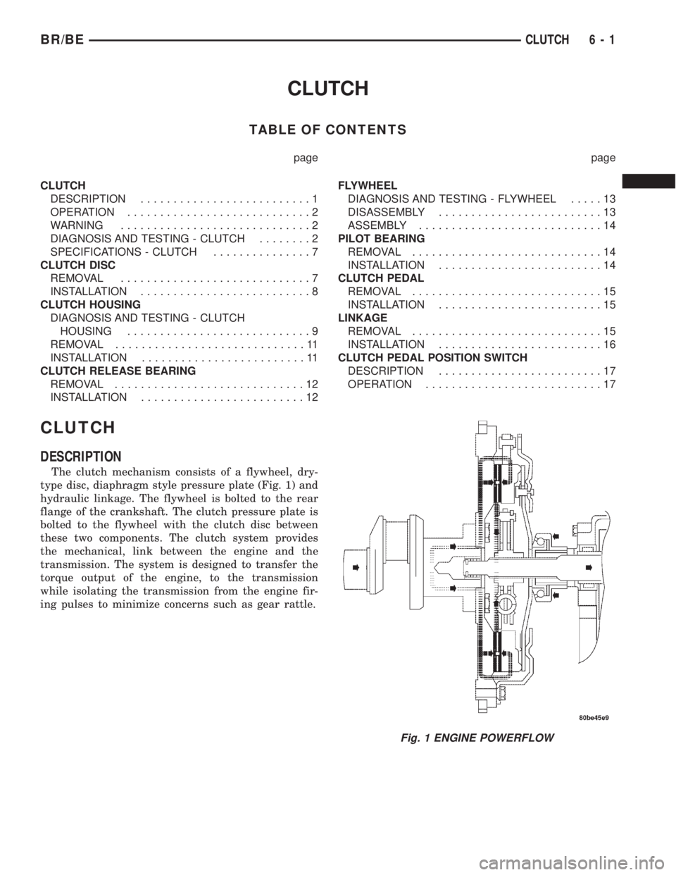
The clutch mechanism consists of a flywheel, dry-
type disc, diaphragm style pressure plate (Fig. 1) and
hydraulic linkage. The flywheel is bolted to the rear
flange of the crankshaft. The clutch pressure plate is
bolted to the flywheel with the clutch disc between
these two components. The clutch system provides
the mechanical, link between the engine and the
transmission. The system is designed to transfer the
torque output of the engine, to the transmission
while isolating the transmission from the engine fir-
ing pulses to minimize concerns such as gear rattle.
Fig. 1 ENGINE POWERFLOW
BR/BECLUTCH 6 - 1
Page 238 of 2255
SPECIFICATIONS - CLUTCH
TORQUE SPECIFICATIONS
DESCRIPTION N´m Ft. Lbs. In. Lbs.
Nut, slave cylinder 19-26 14-19 170-230
Bolt, clutch cover-5/16 in. 23 17 -
Bolt, clutch cover-3/8 in. 41 30 -
Pivot, release bearing 23 17 -
Screw, fluid reservoir 5 - 40
CLUTCH DISC
REMOVAL
(1) Raise and support vehicle.
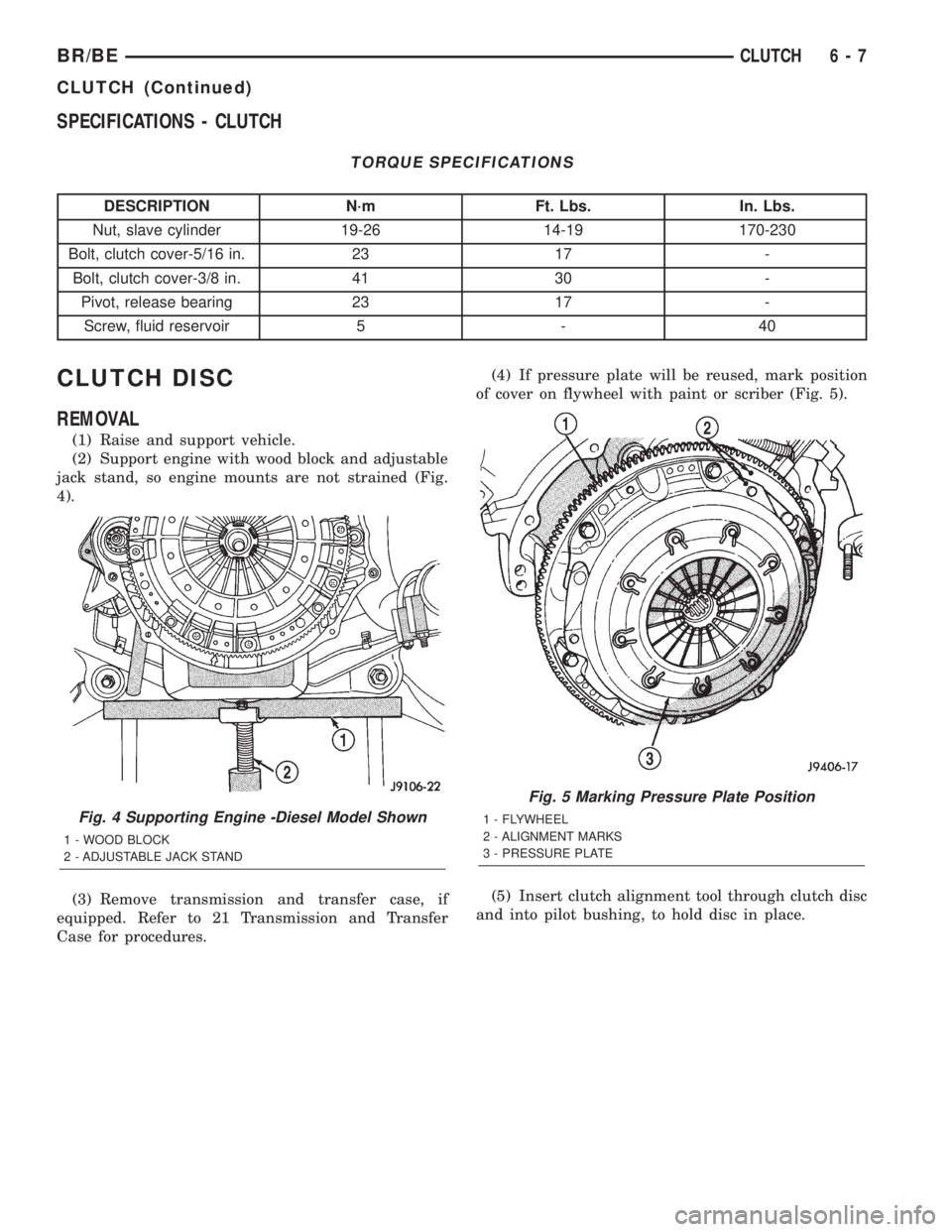
(2) Support engine with wood block and adjustable
jack stand, so engine mounts are not strained (Fig.
4).
(3) Remove transmission and transfer case, if
equipped. Refer to 21 Transmission and Transfer
Case for procedures.(4) If pressure plate will be reused, mark position
of cover on flywheel with paint or scriber (Fig. 5).
(5) Insert clutch alignment tool through clutch disc
and into pilot bushing, to hold disc in place.
Fig. 4 Supporting Engine -Diesel Model Shown
1 - WOOD BLOCK
2 - ADJUSTABLE JACK STAND
Fig. 5 Marking Pressure Plate Position
1 - FLYWHEEL
2 - ALIGNMENT MARKS
3 - PRESSURE PLATE
BR/BECLUTCH 6 - 7
CLUTCH (Continued)