2002 DODGE RAM maintenance schedule
[x] Cancel search: maintenance schedulePage 1177 of 2255
The acceptable levels are indicated between the ADD
and SAFE marks on the engine oil dipstick.
(1) Position vehicle on level surface.
(2) With engine OFF, allow approximately ten min-
utes for oil to settle to bottom of crankcase, remove
engine oil dipstick.
(3) Wipe dipstick clean.
(4) Install dipstick and verify it is seated in the
tube.
(5) Remove dipstick, with handle held above the
tip, take oil level reading.
(6) Add oil only if level is below the ADD mark on
dipstick.
ENGINE OIL CHANGE
Change engine oil at mileage and time intervals
described in the Maintenance Schedule. This infor-
mation can be found in the owner's manual.
TO CHANGE ENGINE OIL
Run engine until achieving normal operating tem-
perature.
(1) Position the vehicle on a level surface and turn
engine off.
(2) Hoist vehicle.
(3) Remove oil fill cap.
(4) Place a suitable drain pan under crankcase
drain.
(5) Remove drain plug from crankcase and allow
oil to drain into pan. Inspect drain plug threads for
stretching or other damage. Replace drain plug and
gasket if damaged.
(6) Install drain plug in crankcase.
(7) Change oil filter (Refer to 9 - ENGINE/LUBRI-
CATION/OIL FILTER - REMOVAL).
(8) Lower vehicle and fill crankcase with specified
type (Refer to LUBRICATION & MAINTENANCE/
FLUID TYPES - DESCRIPTION) and amount of
engine oil (Refer to LUBRICATION & MAINTE-
NANCE - SPECIFICATIONS).
(9) Install oil fill cap.
(10) Start engine and inspect for leaks.
(11) Stop engine and inspect oil level.
OIL FILTER
REMOVAL
All engines are equipped with a high quality full-
flow, disposable type oil filter. DaimlerChrysler Cor-
poration recommends a Mopartor equivalent oil
filter be used.
(1) Position a drain pan under the oil filter.
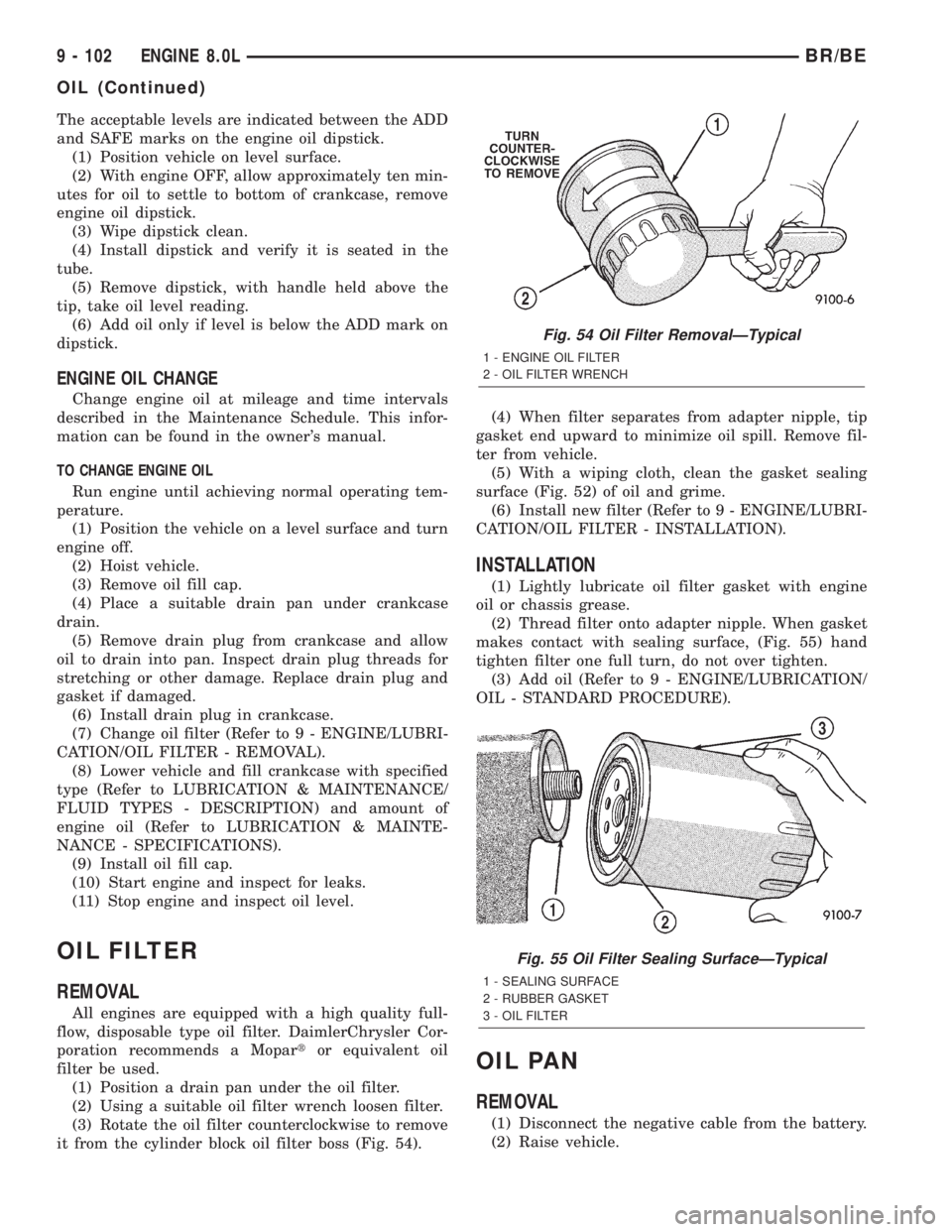
(2) Using a suitable oil filter wrench loosen filter.
(3) Rotate the oil filter counterclockwise to remove
it from the cylinder block oil filter boss (Fig. 54).(4) When filter separates from adapter nipple, tip
gasket end upward to minimize oil spill. Remove fil-
ter from vehicle.
(5) With a wiping cloth, clean the gasket sealing
surface (Fig. 52) of oil and grime.
(6) Install new filter (Refer to 9 - ENGINE/LUBRI-
CATION/OIL FILTER - INSTALLATION).
INSTALLATION
(1) Lightly lubricate oil filter gasket with engine
oil or chassis grease.
(2) Thread filter onto adapter nipple. When gasket
makes contact with sealing surface, (Fig. 55) hand
tighten filter one full turn, do not over tighten.
(3) Add oil (Refer to 9 - ENGINE/LUBRICATION/
OIL - STANDARD PROCEDURE).
OIL PAN
REMOVAL
(1) Disconnect the negative cable from the battery.
(2) Raise vehicle.
Fig. 54 Oil Filter RemovalÐTypical
1 - ENGINE OIL FILTER
2 - OIL FILTER WRENCH
Fig. 55 Oil Filter Sealing SurfaceÐTypical
1 - SEALING SURFACE
2 - RUBBER GASKET
3 - OIL FILTER
9 - 102 ENGINE 8.0LBR/BE
OIL (Continued)
Page 1249 of 2255
INSTALLATION
(1) With engine raised SLIGHTLY, position the
engine mount to the block. Install the bolts and
tighten to 149 N´m (110 ft. lbs.) torque.
(2) Install the thru-bolt into the engine mount.
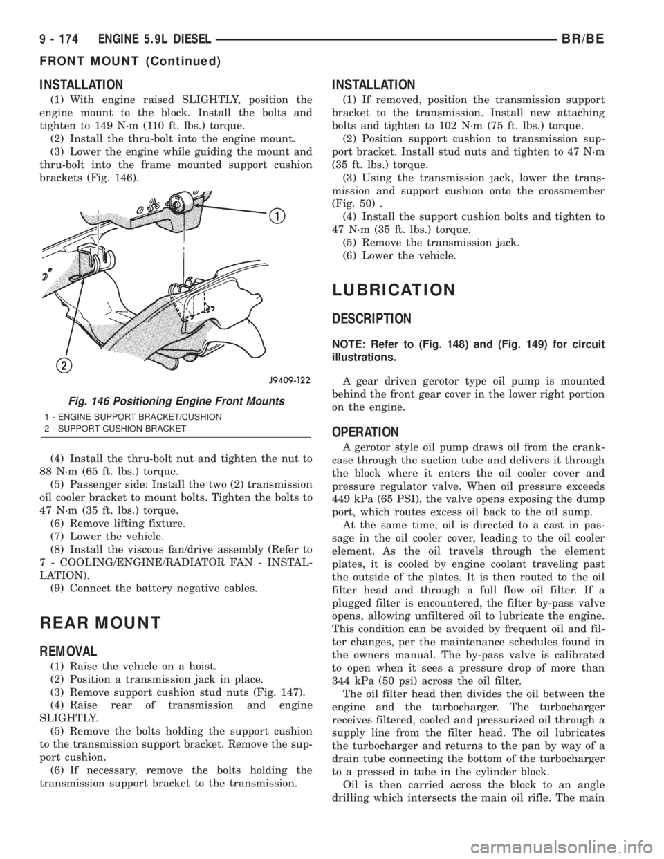
(3) Lower the engine while guiding the mount and
thru-bolt into the frame mounted support cushion
brackets (Fig. 146).
(4) Install the thru-bolt nut and tighten the nut to
88 N´m (65 ft. lbs.) torque.
(5) Passenger side: Install the two (2) transmission
oil cooler bracket to mount bolts. Tighten the bolts to
47 N´m (35 ft. lbs.) torque.
(6) Remove lifting fixture.
(7) Lower the vehicle.
(8) Install the viscous fan/drive assembly (Refer to
7 - COOLING/ENGINE/RADIATOR FAN - INSTAL-
LATION).
(9) Connect the battery negative cables.
REAR MOUNT
REMOVAL
(1) Raise the vehicle on a hoist.
(2) Position a transmission jack in place.
(3) Remove support cushion stud nuts (Fig. 147).
(4) Raise rear of transmission and engine
SLIGHTLY.
(5) Remove the bolts holding the support cushion
to the transmission support bracket. Remove the sup-
port cushion.
(6) If necessary, remove the bolts holding the
transmission support bracket to the transmission.
INSTALLATION
(1) If removed, position the transmission support
bracket to the transmission. Install new attaching
bolts and tighten to 102 N´m (75 ft. lbs.) torque.
(2) Position support cushion to transmission sup-
port bracket. Install stud nuts and tighten to 47 N´m
(35 ft. lbs.) torque.
(3) Using the transmission jack, lower the trans-
mission and support cushion onto the crossmember
(Fig. 50) .
(4) Install the support cushion bolts and tighten to
47 N´m (35 ft. lbs.) torque.
(5) Remove the transmission jack.
(6) Lower the vehicle.
LUBRICATION
DESCRIPTION
NOTE: Refer to (Fig. 148) and (Fig. 149) for circuit
illustrations.
A gear driven gerotor type oil pump is mounted
behind the front gear cover in the lower right portion
on the engine.
OPERATION
A gerotor style oil pump draws oil from the crank-
case through the suction tube and delivers it through
the block where it enters the oil cooler cover and
pressure regulator valve. When oil pressure exceeds
449 kPa (65 PSI), the valve opens exposing the dump
port, which routes excess oil back to the oil sump.
At the same time, oil is directed to a cast in pas-
sage in the oil cooler cover, leading to the oil cooler
element. As the oil travels through the element
plates, it is cooled by engine coolant traveling past
the outside of the plates. It is then routed to the oil
filter head and through a full flow oil filter. If a
plugged filter is encountered, the filter by-pass valve
opens, allowing unfiltered oil to lubricate the engine.
This condition can be avoided by frequent oil and fil-
ter changes, per the maintenance schedules found in
the owners manual. The by-pass valve is calibrated
to open when it sees a pressure drop of more than
344 kPa (50 psi) across the oil filter.
The oil filter head then divides the oil between the
engine and the turbocharger. The turbocharger
receives filtered, cooled and pressurized oil through a
supply line from the filter head. The oil lubricates
the turbocharger and returns to the pan by way of a
drain tube connecting the bottom of the turbocharger
to a pressed in tube in the cylinder block.
Oil is then carried across the block to an angle
drilling which intersects the main oil rifle. The main
Fig. 146 Positioning Engine Front Mounts
1 - ENGINE SUPPORT BRACKET/CUSHION
2 - SUPPORT CUSHION BRACKET
9 - 174 ENGINE 5.9L DIESELBR/BE
FRONT MOUNT (Continued)
Page 1362 of 2255
SPECIAL TOOLS
DIESEL FUEL SYSTEMFUEL FILTER / WATER
SEPARATOR
DESCRIPTION
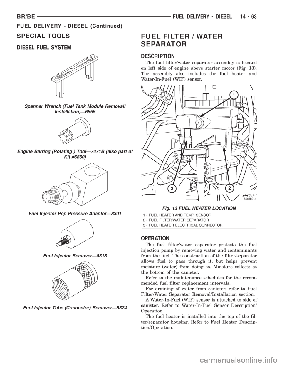
The fuel filter/water separator assembly is located
on left side of engine above starter motor (Fig. 13).
The assembly also includes the fuel heater and
Water-In-Fuel (WIF) sensor.
OPERATION
The fuel filter/water separator protects the fuel
injection pump by removing water and contaminants
from the fuel. The construction of the filter/separator
allows fuel to pass through it, but helps prevent
moisture (water) from doing so. Moisture collects at
the bottom of the canister.
Refer to the maintenance schedules for the recom-
mended fuel filter replacement intervals.
For draining of water from canister, refer to Fuel
Filter/Water Separator Removal/Installation section.
A Water-In-Fuel (WIF) sensor is attached to side of
canister. Refer to Water-In-Fuel Sensor Description/
Operation.
The fuel heater is installed into the top of the fil-
ter/separator housing. Refer to Fuel Heater Descrip-
tion/Operation.
Spanner Wrench (Fuel Tank Module Removal/
Installation)Ð6856
Engine Barring (Rotating ) ToolÐ7471B (also part of
Kit #6860)
Fuel Injector Pop Pressure AdaptorÐ8301
Fuel Injector RemoverÐ8318
Fuel Injector Tube (Connector) RemoverÐ8324
Fig. 13 FUEL HEATER LOCATION
1 - FUEL HEATER AND TEMP. SENSOR
2 - FUEL FILTER/WATER SEPARATOR
3 - FUEL HEATER ELECTRICAL CONNECTOR
BR/BEFUEL DELIVERY - DIESEL 14 - 63
FUEL DELIVERY - DIESEL (Continued)
Page 1363 of 2255
REMOVAL
Refer to maintenance schedules in this manual for
recommended fuel filter replacement intervals.
Draining water from fuel filter/water separa-
tor housing:
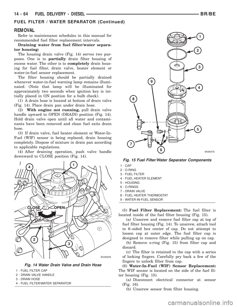
The housing drain valve (Fig. 14) serves two pur-
poses. One is topartiallydrain filter housing of
excess water. The other is tocompletelydrain hous-
ing for fuel filter, drain valve, heater element or
water-in-fuel sensor replacement.
The filter housing should be partially drained
whenever water-in-fuel warning lamp remains illumi-
nated. (Note that lamp will be illuminated for
approximately two seconds when ignition key is ini-
tially placed in ON position for a bulb check).
(1) A drain hose is located at bottom of drain valve
(Fig. 14). Place drain pan under drain hose.
(2)With engine not running,pull drain valve
handle upward to OPEN (DRAIN) position (Fig. 14).
Hold drain valve open until all water and contami-
nants have been removed and clean fuel exits drain
hose.
(3) If drain valve, fuel heater element or Water-In-
Fuel (WIF) sensor is being replaced, drain housing
completely. Dispose of mixture in drain pan according
to applicable regulations.
(4) After draining operation, push valve handle
downward to CLOSE position (Fig. 14).
(5)Fuel Filter Replacement:The fuel filter is
located inside of the fuel filter housing (Fig. 15).
(a) Unscrew and remove fuel filter cap at top of
fuel filter housing (Fig. 14). To unscrew, attach tool
to 6±sided hex center of cap. Do not attempt to
loosen cap at outer edge. The fuel filter cap is
designed to remove filter while pulling up on cap.
(b) Remove o-ring (Fig. 15) from filter cap and
discard.
(c) The filter is retained to the cap with a series
of locking fingers. Carefully pry back a few of the
fingers to unlock filter from cap.
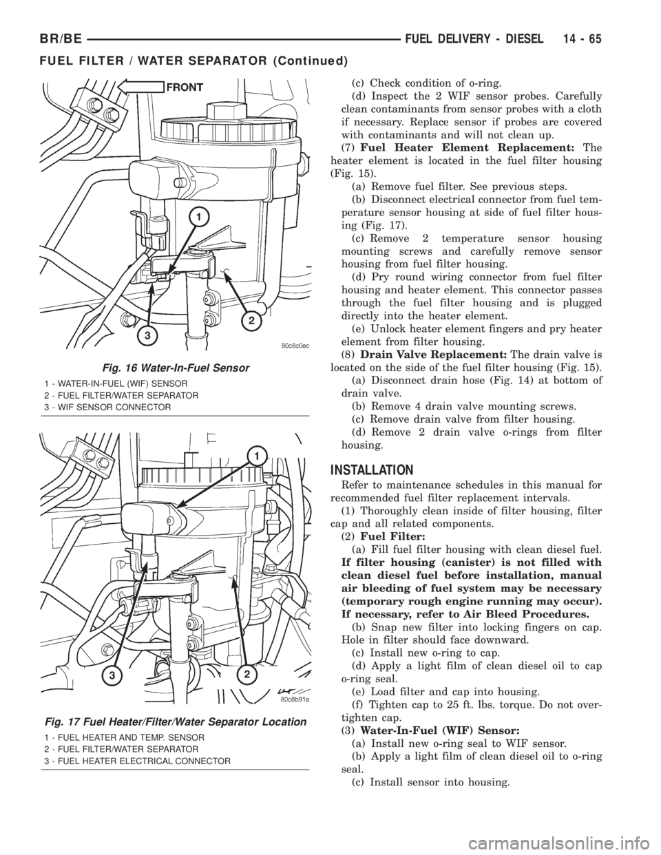
(6)Water-In-Fuel (WIF) Sensor Replacement:
The WIF sensor is located on the side of the fuel fil-
ter housing (Fig. 15).
(a) Disconnect electrical connector at sensor
(Fig. 16).
(b) Unscrew sensor from filter housing.
Fig. 14 Water Drain Valve and Drain Hose
1 - FUEL FILTER CAP
2 - DRAIN VALVE HANDLE
3 - DRAIN HOSE
4 - FUEL FILTER/WATER SEPARATOR
Fig. 15 Fuel Filter/Water Separator Components
1 - CAP
2 - O-RING
3 - FUEL FILTER
4 - FUEL HEATER ELEMENT
5 - HOUSING
6 - O-RINGS
7 - DRAIN VALVE
8 - FUEL HEATER THERMOSTAT
9 - WATER-IN-FUEL SENSOR
14 - 64 FUEL DELIVERY - DIESELBR/BE
FUEL FILTER / WATER SEPARATOR (Continued)
Page 1364 of 2255
(c) Check condition of o-ring.
(d) Inspect the 2 WIF sensor probes. Carefully
clean contaminants from sensor probes with a cloth
if necessary. Replace sensor if probes are covered
with contaminants and will not clean up.
(7)Fuel Heater Element Replacement:The
heater element is located in the fuel filter housing
(Fig. 15).
(a) Remove fuel filter. See previous steps.
(b) Disconnect electrical connector from fuel tem-
perature sensor housing at side of fuel filter hous-
ing (Fig. 17).
(c) Remove 2 temperature sensor housing
mounting screws and carefully remove sensor
housing from fuel filter housing.
(d) Pry round wiring connector from fuel filter
housing and heater element. This connector passes
through the fuel filter housing and is plugged
directly into the heater element.
(e) Unlock heater element fingers and pry heater
element from filter housing.
(8)Drain Valve Replacement:The drain valve is
located on the side of the fuel filter housing (Fig. 15).
(a) Disconnect drain hose (Fig. 14) at bottom of
drain valve.
(b) Remove 4 drain valve mounting screws.
(c) Remove drain valve from filter housing.
(d) Remove 2 drain valve o-rings from filter
housing.
INSTALLATION
Refer to maintenance schedules in this manual for
recommended fuel filter replacement intervals.
(1) Thoroughly clean inside of filter housing, filter
cap and all related components.
(2)Fuel Filter:
(a) Fill fuel filter housing with clean diesel fuel.
If filter housing (canister) is not filled with
clean diesel fuel before installation, manual
air bleeding of fuel system may be necessary
(temporary rough engine running may occur).
If necessary, refer to Air Bleed Procedures.
(b) Snap new filter into locking fingers on cap.
Hole in filter should face downward.
(c) Install new o-ring to cap.
(d) Apply a light film of clean diesel oil to cap
o-ring seal.
(e) Load filter and cap into housing.
(f) Tighten cap to 25 ft. lbs. torque. Do not over-
tighten cap.
(3)Water-In-Fuel (WIF) Sensor:
(a) Install new o-ring seal to WIF sensor.
(b) Apply a light film of clean diesel oil to o-ring
seal.
(c) Install sensor into housing.
Fig. 16 Water-In-Fuel Sensor
1 - WATER-IN-FUEL (WIF) SENSOR
2 - FUEL FILTER/WATER SEPARATOR
3 - WIF SENSOR CONNECTOR
Fig. 17 Fuel Heater/Filter/Water Separator Location
1 - FUEL HEATER AND TEMP. SENSOR
2 - FUEL FILTER/WATER SEPARATOR
3 - FUEL HEATER ELECTRICAL CONNECTOR
BR/BEFUEL DELIVERY - DIESEL 14 - 65
FUEL FILTER / WATER SEPARATOR (Continued)
Page 1449 of 2255
LINKAGE - 2WD
TABLE OF CONTENTS
page page
LINKAGE - 2WD
DESCRIPTION.........................40
STANDARD PROCEDURE - LUBRICATION....40
REMOVAL.............................40
INSTALLATION.........................41SPECIFICATIONS
TORQUE CHART......................41
SPECIAL TOOLS
STEERING LINKAGE...................41
LINKAGE - 2WD
DESCRIPTION
Light duty (LD) and heavy duty (HD) steering link-
age is used with IFS suspensions. The linkage is
comprised of a idler arm, pitman arm, center link
and tie rod ends. Heavy duty linkage is used on 8800
and 10500 lb. GVW vehicles.
CAUTION: If any steering components are replaced
or serviced an alignment must be performed.
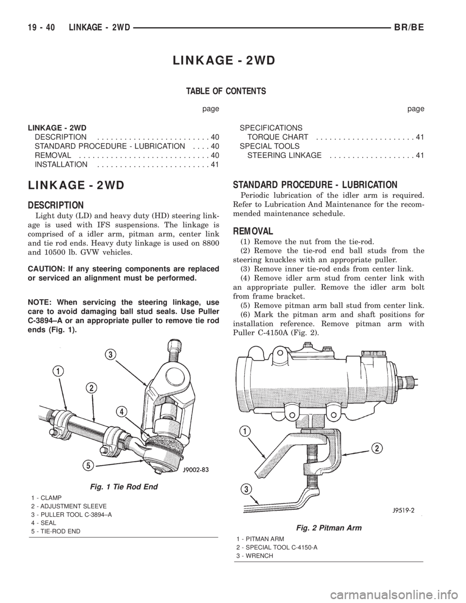
NOTE: When servicing the steering linkage, use
care to avoid damaging ball stud seals. Use Puller
C-3894±A or an appropriate puller to remove tie rod
ends (Fig. 1).
STANDARD PROCEDURE - LUBRICATION
Periodic lubrication of the idler arm is required.
Refer to Lubrication And Maintenance for the recom-
mended maintenance schedule.
REMOVAL
(1) Remove the nut from the tie-rod.
(2) Remove the tie-rod end ball studs from the
steering knuckles with an appropriate puller.
(3) Remove inner tie-rod ends from center link.
(4) Remove idler arm stud from center link with
an appropriate puller. Remove the idler arm bolt
from frame bracket.
(5) Remove pitman arm ball stud from center link.
(6) Mark the pitman arm and shaft positions for
installation reference. Remove pitman arm with
Puller C-4150A (Fig. 2).
Fig. 1 Tie Rod End
1 - CLAMP
2 - ADJUSTMENT SLEEVE
3 - PULLER TOOL C-3894±A
4 - SEAL
5 - TIE-ROD END
Fig. 2 Pitman Arm
1 - PITMAN ARM
2 - SPECIAL TOOL C-4150-A
3 - WRENCH
19 - 40 LINKAGE - 2WDBR/BE
Page 1451 of 2255
LINKAGE - 4WD
TABLE OF CONTENTS
page page
LINKAGE - 4WD
DESCRIPTION.........................42
STANDARD PROCEDURE - LUBRICATION....42
REMOVAL.............................42
INSTALLATION.........................43SPECIFICATIONS
TORQUE CHART......................43
SPECIAL TOOLS
STEERING LINKAGE...................44
LINKAGE - 4WD
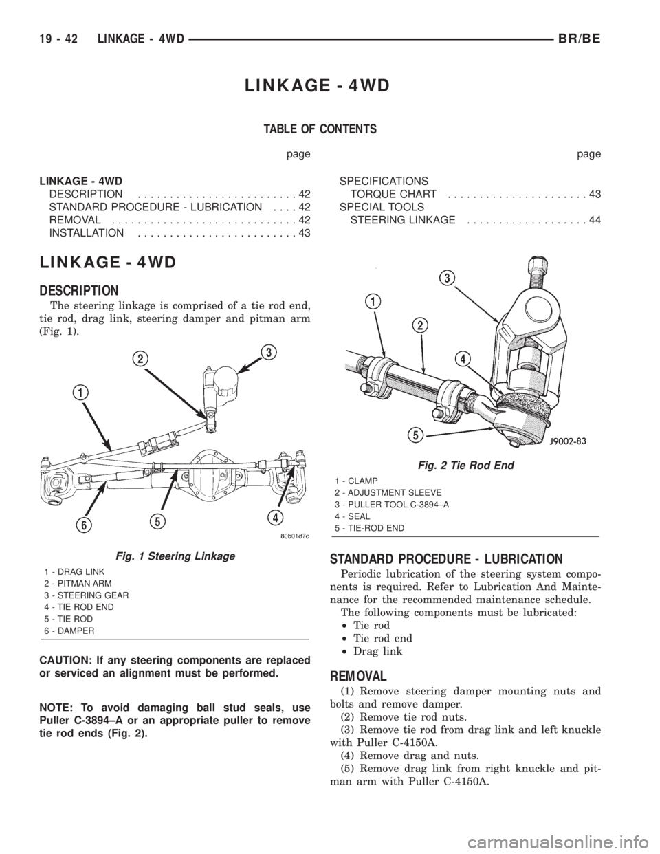
DESCRIPTION
The steering linkage is comprised of a tie rod end,
tie rod, drag link, steering damper and pitman arm
(Fig. 1).
CAUTION: If any steering components are replaced
or serviced an alignment must be performed.
NOTE: To avoid damaging ball stud seals, use
Puller C-3894±A or an appropriate puller to remove
tie rod ends (Fig. 2).
STANDARD PROCEDURE - LUBRICATION
Periodic lubrication of the steering system compo-
nents is required. Refer to Lubrication And Mainte-
nance for the recommended maintenance schedule.
The following components must be lubricated:
²Tie rod
²Tie rod end
²Drag link
REMOVAL
(1) Remove steering damper mounting nuts and
bolts and remove damper.
(2) Remove tie rod nuts.
(3) Remove tie rod from drag link and left knuckle
with Puller C-4150A.
(4) Remove drag and nuts.
(5) Remove drag link from right knuckle and pit-
man arm with Puller C-4150A.
Fig. 1 Steering Linkage
1 - DRAG LINK
2 - PITMAN ARM
3 - STEERING GEAR
4 - TIE ROD END
5 - TIE ROD
6 - DAMPER
Fig. 2 Tie Rod End
1 - CLAMP
2 - ADJUSTMENT SLEEVE
3 - PULLER TOOL C-3894±A
4 - SEAL
5 - TIE-ROD END
19 - 42 LINKAGE - 4WDBR/BE
Page 1957 of 2255
METHOD 1 (RELOCATE WHEEL ON HUB)
(1) Drive vehicle a short distance to eliminate tire
flat spotting from a parked position.
(2) Check wheel bearings and adjust if adjustable
or replace if necessary.
(3) Check the wheel mounting surface.
(4) Relocate wheel on the mounting, two studs
over from the original position.
(5) Tighten wheel nuts until all are properly
torqued, to eliminate brake distortion.
(6) Check radial runout. If still excessive, mark
tire sidewall, wheel, and stud at point of maximum
runout and proceed to Method 2.
METHOD 2 (RELOCATE TIRE ON WHEEL)
NOTE: Rotating the tire on wheel is particularly
effective when there is runout in both tire and
wheel.
(1) Remove tire from wheel and mount wheel on
service dynamic balance machine.
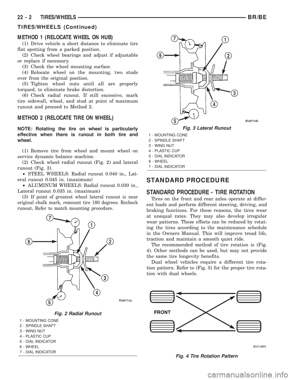
(2) Check wheel radial runout (Fig. 2) and lateral
runout (Fig. 3).
²STEEL WHEELS: Radial runout 0.040 in., Lat-
eral runout 0.045 in. (maximum)
²ALUMINUM WHEELS: Radial runout 0.030 in.,
Lateral runout 0.035 in. (maximum)
(3)
If point of greatest wheel lateral runout is near
original chalk mark, remount tire 180 degrees. Recheck
runout, Refer to match mounting procedure.
STANDARD PROCEDURE
STANDARD PROCEDURE - TIRE ROTATION
Tires on the front and rear axles operate at differ-
ent loads and perform different steering, driving, and
braking functions. For these reasons, the tires wear
at unequal rates. They may also develop irregular
wear patterns. These effects can be reduced by rotat-
ing the tires according to the maintenance schedule
in the Owners Manual. This will improve tread life,
traction and maintain a smooth quiet ride.
The recommended method of tire rotation is (Fig.
4). Other methods can be used, but may not provide
the same tire longevity benefits.
Dual wheel vehicles require a different tire rota-
tion pattern. Refer to (Fig. 5) for the proper tire rota-
tion with dual wheels.
Fig. 2 Radial Runout
1 - MOUNTING CONE
2 - SPINDLE SHAFT
3 - WING NUT
4 - PLASTIC CUP
5 - DIAL INDICATOR
6 - WHEEL
7 - DIAL INDICATOR
Fig. 3 Lateral Runout
1 - MOUNTING CONE
2 - SPINDLE SHAFT
3 - WING NUT
4 - PLASTIC CUP
5 - DIAL INDICATOR
6 - WHEEL
7 - DIAL INDICATOR
Fig. 4 Tire Rotation Pattern
22 - 2 TIRES/WHEELSBR/BE
TIRES/WHEELS (Continued)