2002 DODGE RAM head lamps
[x] Cancel search: head lampsPage 407 of 2255
(5) Remove the battery hold down strap from the
top of the battery case.
INSTALLATION
(1) Clean and inspect the battery hold down hard-
ware (Refer to 8 - ELECTRICAL/BATTERY SYSTEM
- CLEANING).
(2) Position the battery hold down strap across the
top of the battery case.
(3) Install and tighten the two battery hold down
bolts through the holes on each end of the hold down
strap and into the U-nuts on each side of the battery
tray. Tighten the bolts to 4 N´m (35 in. lbs.).
(4) Reconnect the battery negative cable terminal
clamp to the battery negative terminal post. Tighten
the terminal clamp pinch-bolt hex nut to 4 N´m (35
in. lbs.).
BATTERY CABLE
DESCRIPTION
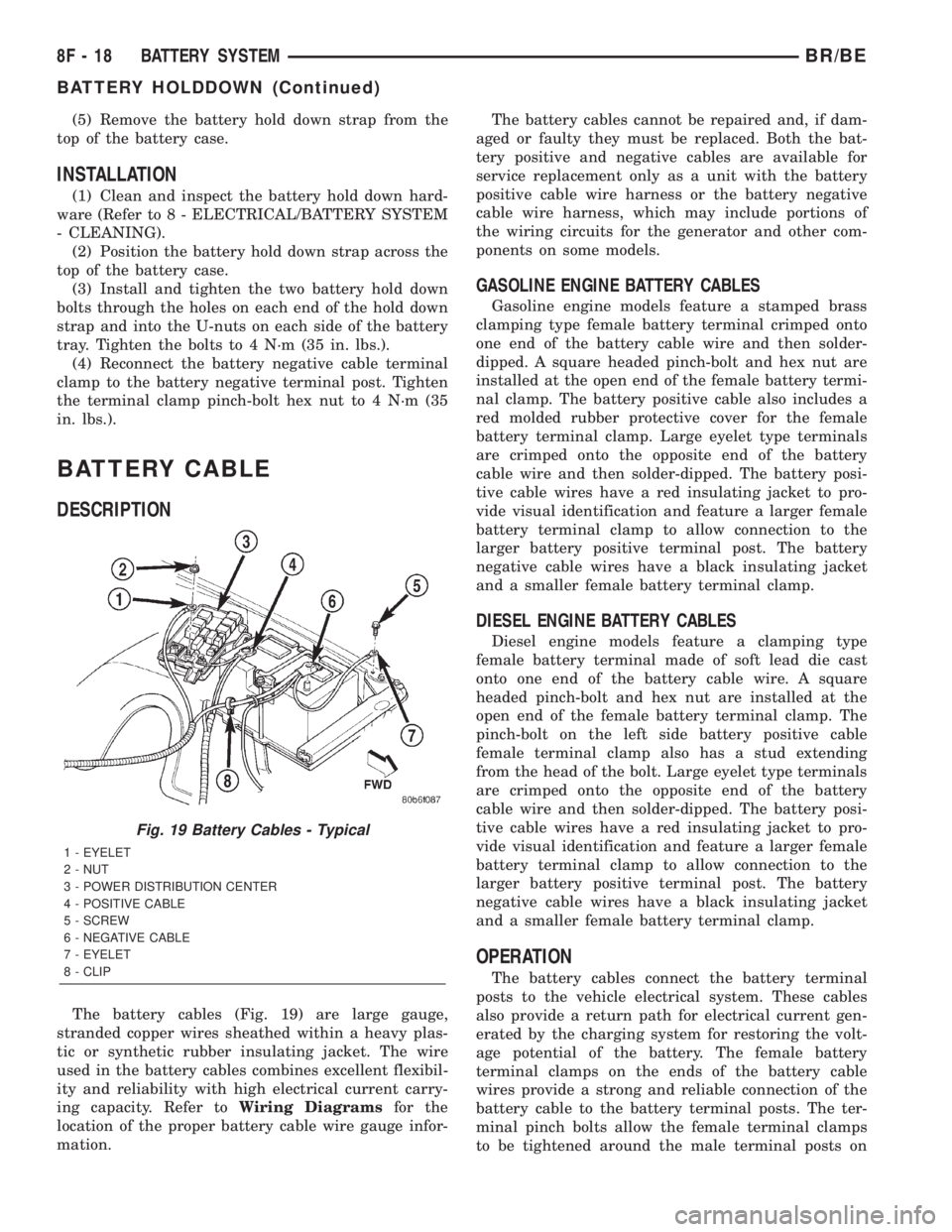
The battery cables (Fig. 19) are large gauge,
stranded copper wires sheathed within a heavy plas-
tic or synthetic rubber insulating jacket. The wire
used in the battery cables combines excellent flexibil-
ity and reliability with high electrical current carry-
ing capacity. Refer toWiring Diagramsfor the
location of the proper battery cable wire gauge infor-
mation.The battery cables cannot be repaired and, if dam-
aged or faulty they must be replaced. Both the bat-
tery positive and negative cables are available for
service replacement only as a unit with the battery
positive cable wire harness or the battery negative
cable wire harness, which may include portions of
the wiring circuits for the generator and other com-
ponents on some models.
GASOLINE ENGINE BATTERY CABLES
Gasoline engine models feature a stamped brass
clamping type female battery terminal crimped onto
one end of the battery cable wire and then solder-
dipped. A square headed pinch-bolt and hex nut are
installed at the open end of the female battery termi-
nal clamp. The battery positive cable also includes a
red molded rubber protective cover for the female
battery terminal clamp. Large eyelet type terminals
are crimped onto the opposite end of the battery
cable wire and then solder-dipped. The battery posi-
tive cable wires have a red insulating jacket to pro-
vide visual identification and feature a larger female
battery terminal clamp to allow connection to the
larger battery positive terminal post. The battery
negative cable wires have a black insulating jacket
and a smaller female battery terminal clamp.
DIESEL ENGINE BATTERY CABLES
Diesel engine models feature a clamping type
female battery terminal made of soft lead die cast
onto one end of the battery cable wire. A square
headed pinch-bolt and hex nut are installed at the
open end of the female battery terminal clamp. The
pinch-bolt on the left side battery positive cable
female terminal clamp also has a stud extending
from the head of the bolt. Large eyelet type terminals
are crimped onto the opposite end of the battery
cable wire and then solder-dipped. The battery posi-
tive cable wires have a red insulating jacket to pro-
vide visual identification and feature a larger female
battery terminal clamp to allow connection to the
larger battery positive terminal post. The battery
negative cable wires have a black insulating jacket
and a smaller female battery terminal clamp.
OPERATION
The battery cables connect the battery terminal
posts to the vehicle electrical system. These cables
also provide a return path for electrical current gen-
erated by the charging system for restoring the volt-
age potential of the battery. The female battery
terminal clamps on the ends of the battery cable
wires provide a strong and reliable connection of the
battery cable to the battery terminal posts. The ter-
minal pinch bolts allow the female terminal clamps
to be tightened around the male terminal posts on
Fig. 19 Battery Cables - Typical
1 - EYELET
2 - NUT
3 - POWER DISTRIBUTION CENTER
4 - POSITIVE CABLE
5 - SCREW
6 - NEGATIVE CABLE
7 - EYELET
8 - CLIP
8F - 18 BATTERY SYSTEMBR/BE
BATTERY HOLDDOWN (Continued)
Page 408 of 2255

the top of the battery. The eyelet terminals secured
to the ends of the battery cable wires opposite the
female battery terminal clamps provide secure and
reliable connection of the battery to the vehicle elec-
trical system.
GASOLINE ENGINE
The battery positive cable terminal clamp is
crimped onto the ends of two wires. One wire has an
eyelet terminal that connects the battery positive
cable to the B(+) terminal stud of the Power Distri-
bution Center (PDC), and the other wire has an eye-
let terminal that connects the battery positive cable
to the B(+) terminal stud of the engine starter motor
solenoid. The battery negative cable terminal clamp
is also crimped onto the ends of two wires. One wire
has an eyelet terminal that connects the battery neg-
ative cable to the vehicle powertrain through a stud
on the front of the left engine cylinder head. The
other wire has an eyelet terminal that connects the
battery negative cable to the vehicle body through a
ground screw on the left front fender inner shield,
just ahead of the battery. An additional ground wire
with two eyelet terminals is used to provide ground
to the vehicle frame. One eyelet terminal of this
ground wire is installed under the head of the bat-
tery negative cable terminal clamp pinch-bolt, and
the other eyelet terminal is secured with a ground
screw to the outer surface of the left frame rail,
below the battery.
DIESEL ENGINE
The left battery positive cable terminal clamp is
die cast onto the ends of two wires. One wire has an
eyelet terminal that connects the left battery positive
cable to the B(+) terminal stud of the Power Distri-
bution Center (PDC), and the other wire has an eye-
let terminal that connects the left battery positive
cable to the B(+) terminal stud of the engine starter
motor solenoid. The right battery positive cable ter-
minal clamp is die cast onto the end of a single wire.
The eyelet terminal on the other end of the right bat-
tery positive cable is connected to the stud on the
pinch-bolt of the left battery positive cable terminal
clamp. This stud also provides a connection point for
the eyelet terminals from the fuel heater relay and
intake air heater relay jumper harness take outs. All
of these eyelet terminals are secured to the left bat-
tery positive cable terminal clamp pinch-bolt stud
with a single hex nut.The left battery negative cable terminal clamp is
die cast onto the ends of two wires. One wire has an
eyelet terminal that connects the left battery nega-
tive cable to the vehicle powertrain through a ground
screw on the left side of the engine block, below the
power steering and vacuum pumps. The other wire
has an eyelet terminal that connects the left battery
negative cable to the vehicle body through a ground
screw on the left front fender inner shield, just ahead
of the left battery. An additional ground wire with
two eyelet terminals is used to provide ground to the
vehicle frame. One eyelet terminal of this ground
wire is installed under the nut of the left battery
negative cable terminal clamp pinch-bolt, and the
other eyelet terminal is secured with a ground screw
to the outer surface of the left frame rail, below the
left battery. The right battery negative cable terminal
is also die cast onto the ends of two wires. One wire
has an eyelet terminal that connects the right bat-
tery negative cable to the vehicle powertrain through
a ground screw on the right side of the engine block,
just forward of the right engine mount. The other
wire has an eyelet terminal that connects the right
battery negative cable to the vehicle body through a
ground screw on the right front fender inner shield,
just behind the right battery.
DIAGNOSIS AND TESTING - BATTERY CABLES
A voltage drop test will determine if there is exces-
sive resistance in the battery cable terminal connec-
tions or the battery cables. If excessive resistance is
found in the battery cable connections, the connec-
tion point should be disassembled, cleaned of all cor-
rosion or foreign material, then reassembled.
Following reassembly, check the voltage drop for the
battery cable connection and the battery cable again
to confirm repair.
When performing the voltage drop test, it is impor-
tant to remember that the voltage drop is giving an
indication of the resistance between the two points at
which the voltmeter probes are attached.EXAM-
PLE:When testing the resistance of the battery pos-
itive cable, touch the voltmeter leads to the battery
positive cable terminal clamp and to the battery pos-
itive cable eyelet terminal at the starter solenoid
B(+) terminal stud. If you probe the battery positive
terminal post and the battery positive cable eyelet
terminal at the starter solenoid B(+) terminal stud,
you are reading the combined voltage drop in the
battery positive cable terminal clamp-to-terminal
post connection and the battery positive cable.
BR/BEBATTERY SYSTEM 8F - 19
BATTERY CABLE (Continued)
Page 438 of 2255
If the heated seat system failure is identified by
flashing heated seat switch indicator lamps, go to the
appropriate diagnosis and testing procedure in this
section and confirm the condition, using the step by
step procedure. If the monitored failure is confirmed,
replace the component. If the monitored failure is not
confirmed, replace the heated seat module with a
known good unit and retest the system.
HEATED SEAT SYSTEM TESTING
Refer toWiring Diagramsfor the location of com-
plete heated seat system wiring diagrams. Before
testing the individual components in the heated seat
system, perform the following preliminary checks:
WARNING: DISABLE THE AIRBAG SYSTEM
BEFORE ATTEMPTING ANY STEERING WHEEL,
STEERING COLUMN, OR INSTRUMENT PANEL
COMPONENT DIAGNOSIS OR SERVICE. DISCON-
NECT AND ISOLATE THE BATTERY NEGATIVE
CABLE, THEN WAIT TWO MINUTES FOR THE AIR-
BAG SYSTEM CAPACITOR TO DISCHARGE
BEFORE PERFORMING FURTHER DIAGNOSIS OR
SERVICE. THIS IS THE ONLY SURE WAY TO DIS-
ABLE THE AIRBAG SYSTEM. FAILURE TO TAKE
THE PROPER PRECAUTIONS COULD RESULT IN
ACCIDENTAL AIRBAG DEPLOYMENT AND POSSI-
BLE PERSONAL INJURY.
²If the heated seat switch back lighting and the
cluster illumination lamps do not illuminate with the
headlamps or park lamps turned On, refer to the
Instrument Clustersection of the service manual
for the location of cluster illumination lamps diagno-
sis and testing procedures. If the heated seat switch
back lighting does not illuminate, but the cluster illu-
mination lamps do illuminate with the headlamps or
park lamps turned On, refer toDiagnosis and Test-
ing the Heated Seat Switchin this section for the
location of the heated seat switch diagnosis and test-
ing procedures.
²If a single indicator lamp for one heated seat
switch does not operate and the heated seat elements
do heat, refer toDiagnosis and Testing the
Heated Seat Switchin this section for heated seat
switch diagnosis and testing procedures.
²If both indicator lamps for a heated seat switch
operate, but the heated seat elements do not heat,
refer toDiagnosis and Testing the Heated Seat
Modulein Electronic Control Modules for heated
seat module diagnosis and testing procedures.
²If none of the indicator lamps for both heated
seat switches will operate and the heated seat ele-
ments for both seats do not heat, refer toDiagnosis
and Testing the Heated Seat Relayin the Power
Distribution section of the service manual for heated
seat relay diagnosis and testing procedures.²If the an indicator lamp on either heated seat
switch remains illuminated after the heated seat has
been turned Off, refer toDiagnosis and Testing
the Heated Seat Modulein Electronic Control
Modules for heated seat module diagnosis and test-
ing procedures. Also refer to the Body Diagnostic
Manual for additional diagnosis and testing proce-
dures.DRIVER SEAT HEATER
SWITCH
DESCRIPTION
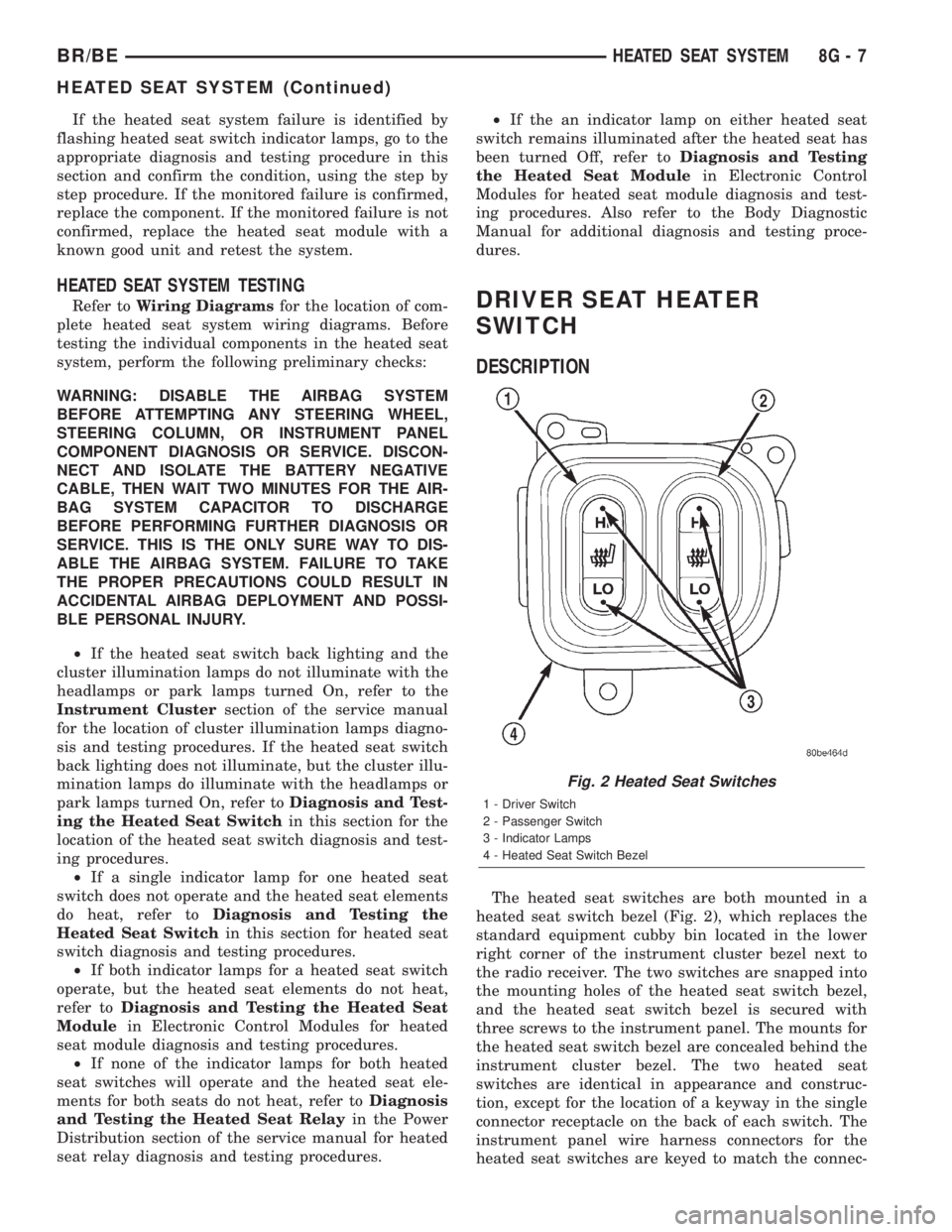
The heated seat switches are both mounted in a
heated seat switch bezel (Fig. 2), which replaces the
standard equipment cubby bin located in the lower
right corner of the instrument cluster bezel next to
the radio receiver. The two switches are snapped into
the mounting holes of the heated seat switch bezel,
and the heated seat switch bezel is secured with
three screws to the instrument panel. The mounts for
the heated seat switch bezel are concealed behind the
instrument cluster bezel. The two heated seat
switches are identical in appearance and construc-
tion, except for the location of a keyway in the single
connector receptacle on the back of each switch. The
instrument panel wire harness connectors for the
heated seat switches are keyed to match the connec-
Fig. 2 Heated Seat Switches
1 - Driver Switch
2 - Passenger Switch
3 - Indicator Lamps
4 - Heated Seat Switch Bezel
BR/BEHEATED SEAT SYSTEM 8G - 7
HEATED SEAT SYSTEM (Continued)
Page 439 of 2255

tor receptacles on the switches so that the two
heated seat switches can only be connected to the
proper heated seat electrical.
The momentary, bidirectional rocker-type heated
seat switch provides a resistor-multiplexed signal to
the heated seat module on the mux circuit. Each
switch has a center neutral position and momentary
Low and High positions so that both the driver and
the front seat passenger can select a preferred level
of seat heating. Each heated seat switch has two
Light-Emitting Diode (LED) indicator lamps, which
indicate the selected mode (Low or High) of the seat
heater. These indicator lamps also provide diagnostic
feedback for the heated seat system. Each switch
also has an incandescent bulb, which provides dim-
mer controlled back lighting of the switch when the
headlamps or park lamps are on.
The two LED indicator lamps and the incandescent
bulb in each heated seat switch cannot be repaired. If
the indicator lamps or back lighting bulb are faulty
or damaged, the individual heated seat switch must
be replaced.
OPERATION
The heated seat switches receive battery current
through a fused ignition switch output (run) circuit
when the ignition switch is in the On position.
Depressing the heated seat switch rocker to its
momentary High or Low position provides a hard-
wired resistor multiplexed voltage request signal to
the heated seat module to power the heated seat ele-
ment of the selected seat and maintain the requested
temperature setting. If the heated seat switch is
depressed to a different position (Low or High) than
the currently selected state, the heated seat module
will change states to support the new selection. If a
heated seat switch is depressed a second time to the
same position as the currently selected state, the
heated seat module interprets the second input as a
request to turn the seat heater off. The heated seat
module will then turn the heated seat elements for
that seat off.
The indicator lamps in the heated seat switches
receive battery current through a fused ignition
switch output (run) circuit when the ignition switch
is in the On position. The ground side of each indi-
cator lamp is controlled by a separate (high or low/
driver or passenger) indicator lamp driver circuit by
the heated seat module. The heated seat module con-
trol of the switch indicator lamps also allows the
module to provide diagnostic feedback to the vehicle
operator to indicate monitored heated seat system
faults by flashing the indicator lamps on and off. One
side of the incandescent back lighting bulb in each
heated seat switch is connected to ground at all
times. The other side of the incandescent bulb is con-nected to the fused panel lamps dimmer switch sig-
nal circuit. These bulbs are energized when the park
lamps or headlamps are turned on, and their illumi-
nation intensity is controlled by the panel lamps dim-
mer switch.
DIAGNOSIS AND TESTING - HEATED SEAT
SWITCH
Refer toWiring Diagramsfor the location of com-
plete heated seat system wiring diagrams.
WARNING: DISABLE THE AIRBAG SYSTEM
BEFORE ATTEMPTING ANY STEERING WHEEL,
STEERING COLUMN, OR INSTRUMENT PANEL
COMPONENT DIAGNOSIS OR SERVICE. DISCON-
NECT AND ISOLATE THE BATTERY NEGATIVE
(GROUND) CABLE, THEN WAIT TWO MINUTES FOR
THE AIRBAG SYSTEM CAPACITOR TO DISCHARGE
BEFORE PERFORMING FURTHER DIAGNOSIS OR
SERVICE. THIS IS THE ONLY SURE WAY TO DIS-
ABLE THE AIRBAG SYSTEM. FAILURE TO TAKE
THE PROPER PRECAUTIONS COULD RESULT IN
ACCIDENTAL AIRBAG DEPLOYMENT AND POSSI-
BLE PERSONAL INJURY.
(1) If the problem being diagnosed involves inoper-
ative heated seat switch back lighting and the cluster
illumination lamps operate, go to Step 2. If the prob-
lem being diagnosed involves inoperative heated seat
switch back lighting and the cluster illumination
lamps are also inoperative, refer toInstrument
Clusterin the index of this service manual for the
proper cluster illumination lamps diagnosis and test-
ing procedures. If the problem being diagnosed
involves inoperative heated seat switch indicator
lamps and the heated seat elements do not heat,
refer to Step 4. If the problem being diagnosed
involves inoperative heated seat switch indicator
lamps and the heated seat elements do heat, go to
Step 8. If the problem being diagnosed involves a
heated seat switch indicator lamp that remains illu-
minated after the heated seat has been turned Off,
refer toHeated Seat Modulein Electronic Control
Modules for the location of the proper heated seat
module diagnosis and testing procedures. Also refer
to the Body Diagnostic Manual for additional diagno-
sis and testing procedures.
(2) Disconnect and isolate the battery negative
cable. Remove the heated seat switch and bezel unit
from the instrument panel. Disconnect the instru-
ment panel wire harness connector from the connec-
tor receptacle on the back of the heated seat switch
to be tested. Check for continuity between the ground
circuit cavity of the instrument panel wire harness
connector for the heated seat switch and a good
ground. There should be continuity. If OK, go to Step
8G - 8 HEATED SEAT SYSTEMBR/BE
DRIVER SEAT HEATER SWITCH (Continued)
Page 440 of 2255

3. If not OK, repair the open ground circuit to ground
as required.
(3) Reconnect the battery negative cable. Turn the
park lamps on with the headlamp switch. Rotate the
panel lamps dimmer thumbwheel on the headlamp
switch upward to just before the interior lamps
detent. Check for battery voltage at the fused panel
lamps dimmer switch signal circuit cavity of the
instrument panel wire harness connector for the
heated seat switch. If OK, replace the faulty heated
seat switch. If not OK, repair the open fused panel
lamps dimmer switch signal circuit to the fuse in the
Junction Block (JB) as required.
(4) Check the fused ignition switch output (run)
fuse in the Junction Block (JB). If OK, go to Step 5.
If not OK, repair the shorted circuit or component as
required and replace the faulty fuse.
(5) Turn the ignition switch to the On position.
Check for battery voltage at the fused ignition switch
output (run) fuse in the JB. If OK, go to Step 6. If
not OK, repair the open fused ignition switch output
(run) circuit to the ignition switch as required.
(6) Disconnect and isolate the battery negative
cable. Remove the heated seat switch and bezel unit
from the instrument panel. Disconnect the instru-
ment panel wire harness connector from the connec-
tor receptacle on the back of the heated seat switch
to be tested. Reconnect the battery negative cable.
Turn the ignition switch to the On position. Check
for battery voltage at the fused ignition switch out-
put (run) circuit cavity of the instrument panel wire
harness connector for the heated seat switch. If OK,
go to Step 7. If not OK, repair the open fused ignition
switch output (run) circuit to the JB fuse as required.
(7) Check the continuity and resistance values of
the heated seat switch in the Neutral, Low and High
positions as shown in the Heated Seat Switch Conti-
nuity chart (Fig. 3). If OK, refer toHeated Seat
Modulein Electronic Control Modules for the loca-
tion of the proper heated seat module diagnosis and
testing procedures. Also refer to the Body Diagnostic
Manual for additional diagnosis and testing proce-
dures. If not OK, replace the faulty heated seat
switch.
NOTE: ANY RESISTANCE VALUES (OHMSV) GIVEN
IN THE FOLLOWING TEXT ARE SUPPLIED USING
THE AUTOMATIC RANGE GENERATED BY A
FLUKETAUTOMOTIVE METER. IF ANOTHER TYPE
OF MEASURING DEVICE IS USED THE VALUES
GENERATED MAY NOT BE THE SAME AS THE
RESULTS SHOWN HERE, OR MAY HAVE TO BE
CONVERTED TO THE RANGE USED HERE.
Heated Seat Switch Continuity
Switch PositionContinuity
BetweenResistance
Neutral 4 & 6 2.2 Kilohms
Low 4 & 6 .415 Kilohms
High 4 & 6 33 Ohms
(8) Replace the inoperative heated seat switch
with a known good unit and test the operation of the
switch indicator lamps. If OK, discard the faulty
heated seat switch. If not OK, refer toHeated Seat
Modulein Electronic Control Modules for the loca-
tion of the proper heated seat module diagnosis and
testing procedures. Also refer to the Body Diagnostic
Manual for additional diagnosis and testing proce-
dures.
REMOVAL
Both heated seat switches and the heated seat
switch bezel are available individually for service
replacement.
(1) Disconnect and isolate the battery negative
cable.
(2) Remove the cluster bezel from the instrument
panel. Refer toCluster Bezelin the index of this
service manual for the location of the proper cluster
bezel removal procedures.
(3) Remove the three screws that secure the
heated seat switch bezel to the instrument panel
(Fig. 4).
(4) Pull the heated seat switch bezel out from the
instrument panel far enough to access and disconnect
the two instrument panel wire harness connectors
from the connector receptacles on the backs of the
heated seat switches.
(5) Remove the heated seat switch bezel and both
switches from the instrument panel as a unit.
Fig. 3 Heated Seat Switch
BR/BEHEATED SEAT SYSTEM 8G - 9
DRIVER SEAT HEATER SWITCH (Continued)
Page 448 of 2255
the front seat passenger can select a preferred level
of seat heating. Each heated seat switch has two
Light-Emitting Diode (LED) indicator lamps, which
indicate the selected mode (Low or High) of the seat
heater. These indicator lamps also provide diagnostic
feedback for the heated seat system. Each switch
also has an incandescent bulb, which provides dim-
mer controlled back lighting of the switch when the
headlamps or park lamps are on.
The two LED indicator lamps and the incandescent
bulb in each heated seat switch cannot be repaired. If
the indicator lamps or back lighting bulb are faulty
or damaged, the individual heated seat switch must
be replaced.
OPERATION
The heated seat switches receive battery current
through a fused ignition switch output (run) circuit
when the ignition switch is in the On position.
Depressing the heated seat switch rocker to its
momentary High or Low position provides a hard-
wired resistor multiplexed voltage request signal to
the heated seat module to power the heated seat ele-
ment of the selected seat and maintain the requested
temperature setting. If the heated seat switch is
depressed to a different position (Low or High) than
the currently selected state, the heated seat module
will change states to support the new selection. If a
heated seat switch is depressed a second time to thesame position as the currently selected state, the
heated seat module interprets the second input as a
request to turn the seat heater off. The heated seat
module will then turn the heated seat elements for
that seat off.
The indicator lamps in the heated seat switches
receive battery current through a fused ignition
switch output (run) circuit when the ignition switch
is in the On position. The ground side of each indi-
cator lamp is controlled by a separate (high or low/
driver or passenger) indicator lamp driver circuit by
the heated seat module. The heated seat module con-
trol of the switch indicator lamps also allows the
module to provide diagnostic feedback to the vehicle
operator to indicate monitored heated seat system
faults by flashing the indicator lamps on and off. One
side of the incandescent back lighting bulb in each
heated seat switch is connected to ground at all
times. The other side of the incandescent bulb is con-
nected to the fused panel lamps dimmer switch sig-
nal circuit. These bulbs are energized when the park
lamps or headlamps are turned on, and their illumi-
nation intensity is controlled by the panel lamps dim-
mer switch.
DIAGNOSIS AND TESTING - HEATED SEAT
SWITCH
Refer toWiring Diagramsfor the location of com-
plete heated seat system wiring diagrams.
WARNING: DISABLE THE AIRBAG SYSTEM
BEFORE ATTEMPTING ANY STEERING WHEEL,
STEERING COLUMN, OR INSTRUMENT PANEL
COMPONENT DIAGNOSIS OR SERVICE. DISCON-
NECT AND ISOLATE THE BATTERY NEGATIVE
(GROUND) CABLE, THEN WAIT TWO MINUTES FOR
THE AIRBAG SYSTEM CAPACITOR TO DISCHARGE
BEFORE PERFORMING FURTHER DIAGNOSIS OR
SERVICE. THIS IS THE ONLY SURE WAY TO DIS-
ABLE THE AIRBAG SYSTEM. FAILURE TO TAKE
THE PROPER PRECAUTIONS COULD RESULT IN
ACCIDENTAL AIRBAG DEPLOYMENT AND POSSI-
BLE PERSONAL INJURY.
(1) If the problem being diagnosed involves inoper-
ative heated seat switch back lighting and the cluster
illumination lamps operate, go to Step 2. If the prob-
lem being diagnosed involves inoperative heated seat
switch back lighting and the cluster illumination
lamps are also inoperative, refer toInstrument
Clusterin the index of this service manual for the
proper cluster illumination lamps diagnosis and test-
ing procedures. If the problem being diagnosed
involves inoperative heated seat switch indicator
lamps and the heated seat elements do not heat,
refer to Step 4. If the problem being diagnosed
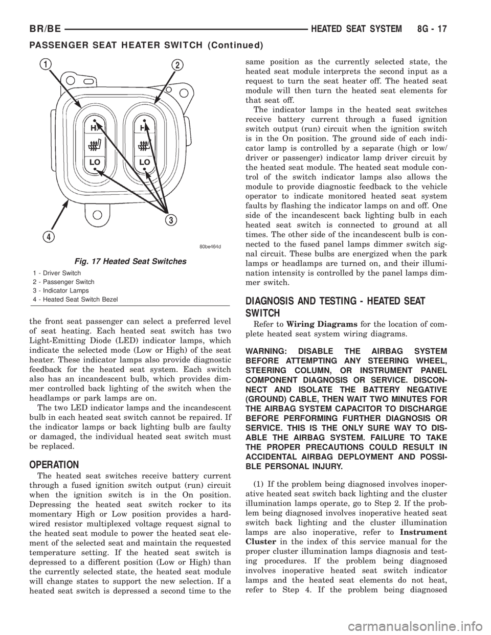
Fig. 17 Heated Seat Switches
1 - Driver Switch
2 - Passenger Switch
3 - Indicator Lamps
4 - Heated Seat Switch Bezel
BR/BEHEATED SEAT SYSTEM 8G - 17
PASSENGER SEAT HEATER SWITCH (Continued)
Page 449 of 2255

involves inoperative heated seat switch indicator
lamps and the heated seat elements do heat, go to
Step 8. If the problem being diagnosed involves a
heated seat switch indicator lamp that remains illu-
minated after the heated seat has been turned Off,
refer toHeated Seat Modulein Electronic Control
Modules for the location of the proper heated seat
module diagnosis and testing procedures. Also refer
to the Body Diagnostic Manual for additional diagno-
sis and testing procedures.
(2) Disconnect and isolate the battery negative
cable. Remove the heated seat switch and bezel unit
from the instrument panel. Disconnect the instru-
ment panel wire harness connector from the connec-
tor receptacle on the back of the heated seat switch
to be tested. Check for continuity between the ground
circuit cavity of the instrument panel wire harness
connector for the heated seat switch and a good
ground. There should be continuity. If OK, go to Step
3. If not OK, repair the open ground circuit to ground
as required.
(3) Reconnect the battery negative cable. Turn the
park lamps on with the headlamp switch. Rotate the
panel lamps dimmer thumbwheel on the headlamp
switch upward to just before the interior lamps
detent. Check for battery voltage at the fused panel
lamps dimmer switch signal circuit cavity of the
instrument panel wire harness connector for the
heated seat switch. If OK, replace the faulty heated
seat switch. If not OK, repair the open fused panel
lamps dimmer switch signal circuit to the fuse in the
Junction Block (JB) as required.
(4) Check the fused ignition switch output (run)
fuse in the Junction Block (JB). If OK, go to Step 5.
If not OK, repair the shorted circuit or component as
required and replace the faulty fuse.
(5) Turn the ignition switch to the On position.
Check for battery voltage at the fused ignition switch
output (run) fuse in the JB. If OK, go to Step 6. If
not OK, repair the open fused ignition switch output
(run) circuit to the ignition switch as required.
(6) Disconnect and isolate the battery negative
cable. Remove the heated seat switch and bezel unit
from the instrument panel. Disconnect the instru-
ment panel wire harness connector from the connec-
tor receptacle on the back of the heated seat switch
to be tested. Reconnect the battery negative cable.
Turn the ignition switch to the On position. Check
for battery voltage at the fused ignition switch out-
put (run) circuit cavity of the instrument panel wire
harness connector for the heated seat switch. If OK,
go to Step 7. If not OK, repair the open fused ignition
switch output (run) circuit to the JB fuse as required.
(7) Check the continuity and resistance values of
the heated seat switch in the Neutral, Low and High
positions as shown in the Heated Seat Switch Conti-nuity chart (Fig. 18). If OK, refer toHeated Seat
Modulein Electronic Control Modules for the loca-
tion of the proper heated seat module diagnosis and
testing procedures. Also refer to the Body Diagnostic
Manual for additional diagnosis and testing proce-
dures. If not OK, replace the faulty heated seat
switch.
NOTE: ANY RESISTANCE VALUES (OHMSV) GIVEN
IN THE FOLLOWING TEXT ARE SUPPLIED USING
THE AUTOMATIC RANGE GENERATED BY A
FLUKETAUTOMOTIVE METER. IF ANOTHER TYPE
OF MEASURING DEVICE IS USED THE VALUES
GENERATED MAY NOT BE THE SAME AS THE
RESULTS SHOWN HERE, OR MAY HAVE TO BE
CONVERTED TO THE RANGE USED HERE.
Heated Seat Switch Continuity
Switch PositionContinuity
BetweenResistance
Neutral 4 & 6 2.2 Kilohms
Low 4 & 6 .415 Kilohms
High 4 & 6 33 Ohms
(8) Replace the inoperative heated seat switch
with a known good unit and test the operation of the
switch indicator lamps. If OK, discard the faulty
heated seat switch. If not OK, refer toHeated Seat
Modulein Electronic Control Modules for the loca-
tion of the proper heated seat module diagnosis and
testing procedures. Also refer to the Body Diagnostic
Manual for additional diagnosis and testing proce-
dures.
REMOVAL
Both heated seat switches and the heated seat
switch bezel are available individually for service
replacement.
Fig. 18 Heated Seat Switch
8G - 18 HEATED SEAT SYSTEMBR/BE
PASSENGER SEAT HEATER SWITCH (Continued)
Page 484 of 2255

trol some of the VFD functions requires the use of a
DRBIIItscan tool. Refer to the appropriate diagnos-
tic information. Specific operation details for the
odometer and trip odometer functions of the VFD
may be found elsewhere in this service manual.
INDICATORS
Indicators are located in various positions within
the EMIC and are all connected to the EMIC circuit
board. The four-wheel drive indicator, high beam
indicator, washer fluid indicator, turn signal indica-
tors, and wait-to-start indicator are hard wired. The
brake indicator is controlled by CCD data bus mes-
sages from the Controller Anti-lock Brake (CAB) and
the hard wired park brake switch input to the EMIC.
The seatbelt indicator is controlled by the EMIC pro-
gramming, CCD data bus messages from the Airbag
Control Module (ACM), and the hard wired seat belt
switch input to the EMIC. The Malfunction Indicator
Lamp (MIL) is normally controlled by CCD data bus
messages from the Powertrain Control Module
(PCM); however, if the EMIC loses CCD data bus
communications, the EMIC circuitry will automati-
cally turn the MIL on, and flash the odometer VFD
on and off repeatedly until CCD data bus communi-
cation is restored. The EMIC uses CCD data bus
messages from the Powertrain Control Module
(PCM), the diesel engine only Engine Control Module
(ECM), the ACM, and the CAB to control all of the
remaining indicators. Different indicators are con-
trolled by different strategies; some receive fused
ignition switch output from the EMIC circuitry clus-
ter and have a switched ground, while others are
grounded through the EMIC circuitry and have a
switched battery feed.
In addition, certain indicators in this instrument
cluster are programmable or configurable. This fea-
ture allows the programmable indicators to be acti-
vated or deactivated with a DRBIIItscan tool, while
the configurable indicators will be automatically
enabled or disabled by the EMIC circuitry for com-
patibility with certain optional equipment. The only
programmable indicator for this model is the upshift
indicator. The cruise indicator, four-wheel drive indi-
cator, overdrive-off indicator, service reminder indica-
tor, and the transmission overtemp indicator are
automatically configured, either electronically or
mechanically.
The hard wired indicators are diagnosed using con-
ventional diagnostic methods. The EMIC and CCD
bus message controlled indicator lamps are diagnosed
using the EMIC self-diagnostic actuator test. (Refer
to 8 - ELECTRICAL/INSTRUMENT CLUSTER -
DIAGNOSIS AND TESTING). Proper testing of the
CCD data bus and the data bus message inputs to
the EMIC that control each indicator lamp requirethe use of a DRBIIItscan tool. Refer to the appro-
priate diagnostic information. Specific operation
details for each indicator may be found elsewhere in
this service manual.
CLUSTER ILLUMINATION
The EMIC has several illumination lamps that are
illuminated when the exterior lighting is turned on
with the headlamp switch. The illumination bright-
ness of these lamps is adjusted by the panel lamps
dimmer rheostat when the headlamp switch thumb-
wheel is rotated (down to dim, up to brighten). The
illumination lamps receive battery current through
the panel lamps dimmer rheostat and a fuse in the
JB on a fused panel lamps dimmer switch signal cir-
cuit. The illumination lamps are grounded at all
times.
In addition, an analog/digital (A/D) converter in
the EMIC converts the analog panel lamps dimmer
rheostat input from the headlamp switch to a digital
dimming level signal for controlling the lighting level
of the VFD. The EMIC also broadcasts this digital
dimming information as a message over the CCD
data bus for use by the Compass Mini-Trip Computer
(CMTC) in synchronizing the lighting level of its
VFD with that of the EMIC. The headlamp switch
thumbwheel also has a Parade position to provide a
parade mode. The EMIC monitors the request for
this mode through a hard wired day brightness sense
circuit input from the headlamp switch. In this mode,
the EMIC will override the selected panel dimmer
switch signal and send a message over the CCD data
bus to illuminate all vacuum fluorescent displays at
full brightness for easier visibility when driving in
daylight with the exterior lighting turned on. The
parade mode has no effect on the incandescent bulb
illumination intensity.
The hard wired cluster illumination lamps are
diagnosed using conventional diagnostic methods.
Proper testing of the VFD dimming level and the
CCD data bus dimming level message functions
requires the use of a DRBIIItscan tool. Refer to the
appropriate diagnostic information.
CHIME WARNING REQUESTS
The EMIC is programmed to request chime service
from the Central Timer Module (CTM) when certain
indicator lamps are illuminated. When the pro-
grammed conditions are met, the EMIC generates a
chime request signal and sends it over a hard wired
tone request circuit to the CTM. Upon receiving the
proper chime request, the CTM activates an integral
chime tone generator to provide the audible chime
tone to the vehicle operator. (Refer to 8 - ELECTRI-
CAL/CHIME/BUZZER - OPERATION). Proper test-
ing of the CTM and the EMIC chime requests
BR/BEINSTRUMENT CLUSTER 8J - 5
INSTRUMENT CLUSTER (Continued)