2002 DODGE RAM cruise control
[x] Cancel search: cruise controlPage 497 of 2255
indicator or the instrument cluster circuitry that con-
trols the LED, (Refer to 8 - ELECTRICAL/INSTRU-
MENT CLUSTER - DIAGNOSIS AND TESTING).
For proper diagnosis of the PCM, the CCD data bus,
or the message inputs to the instrument cluster that
control the check gauges indicator, a DRBIIItscan
tool is required. Refer to the appropriate diagnostic
information.
CRUISE INDICATOR
DESCRIPTION
A cruise indicator is standard equipment on all
instrument clusters. However, on vehicles not
equipped with the optional speed control system, this
indicator is electronically disabled. The cruise indica-
tor consists of the word ªCRUISEº, which appears in
the lower portion of the odometer/trip odometer Vac-
uum-Fluorescent Display (VFD). The VFD is part of
the cluster electronic circuit board, and is visible
through a cutout located in the lower left corner of
the cluster overlay. The dark lens of the VFD pre-
vents the indicator from being clearly visible when it
is not illuminated. The word ªCRUISEº appears in
an amber color and at the same lighting level as the
odometer/trip odometer information when it is illumi-
nated by the instrument cluster electronic circuit
board. The cruise indicator is serviced as a unit with
the VFD in the instrument cluster.
OPERATION
The cruise indicator gives an indication to the vehi-
cle operator when the speed control system is turned
On, regardless of whether the speed control is
engaged. This indicator is controlled by the instru-
ment cluster circuit board based upon the cluster
programming and electronic messages received by
the cluster from the Powertrain Control Module
(PCM) over the Chrysler Collision Detection (CCD)
data bus. The cruise indicator receives battery cur-
rent on the instrument cluster electronic circuit
board through the fused ignition switch output (st-
run) circuit whenever the ignition switch is in the On
or Start positions; therefore, the indicator will always
be off when the ignition switch is in any position
except On or Start. The indicator only illuminates
when it is switched to ground by the instrument clus-
ter circuitry. The instrument cluster will turn on the
cruise indicator for the following reasons:
²Bulb Test- Each time the ignition switch is
turned to the On position the cruise indicator is illu-
minated for about two seconds as a bulb test.
²Cruise Lamp-On Message- Each time the
cluster receives a cruise lamp-on message from the
PCM indicating the speed control system has beenturned On, the cruise indicator is illuminated. The
indicator remains illuminated until the cluster
receives a cruise lamp-off message from the PCM or
until the ignition switch is turned to the Off position,
whichever occurs first.
²Actuator Test- Each time the cluster is put
through the actuator test, the cruise indicator will be
turned on during the VFD portion of the test to con-
firm the functionality of the VFD, and again during
the bulb check portion of the test to confirm the func-
tionality of the cluster control circuitry.
The PCM continually monitors the speed control
switches to determine the proper outputs to the
speed control servo. The PCM then sends the proper
cruise indicator lamp-on and lamp-off messages to
the instrument cluster. For further diagnosis of the
cruise indicator or the instrument cluster circuitry
that controls the indicator, (Refer to 8 - ELECTRI-
CAL/INSTRUMENT CLUSTER - DIAGNOSIS AND
TESTING). For proper diagnosis of the speed control
system, the PCM, the CCD data bus, or the message
inputs to the instrument cluster that control the
cruise indicator, a DRBIIItscan tool is required.
Refer to the appropriate diagnostic information.
ENGINE TEMPERATURE
GAUGE
DESCRIPTION
An engine coolant temperature gauge is standard
equipment on all instrument clusters. The engine
coolant temperature gauge is located in the lower left
quadrant of the instrument cluster, below the voltage
gauge. The engine coolant temperature gauge con-
sists of a movable gauge needle or pointer controlled
by the instrument cluster circuitry and a fixed 90
degree scale on the cluster overlay that reads left-to-
right from 54É C (130É F) to 127É C (260É F) for gas-
oline engines, or from 60É C (140É F) to 116É C (240É
F) for diesel engines. An International Control and
Display Symbol icon for ªEngine Coolant Tempera-
tureº is located on the cluster overlay, directly below
the lowest graduation of the gauge scale. The engine
coolant temperature gauge graphics are white
against a black field except for a single red gradua-
tion at the high end of the gauge scale, making them
clearly visible within the instrument cluster in day-
light. When illuminated from behind by the panel
lamps dimmer controlled cluster illumination lighting
with the exterior lamps turned On, the white graph-
ics appear blue-green and the red graphics appear
red. The orange gauge needle is internally illumi-
nated. Gauge illumination is provided by replaceable
incandescent bulb and bulb holder units located on
the instrument cluster electronic circuit board. The
8J - 18 INSTRUMENT CLUSTERBR/BE
CHECK GAUGES INDICATOR (Continued)
Page 1329 of 2255
(9) Inspect fuel tube quick-connect fitting-to-fuel
rail connections.
(10) Verify that hose connections to all ports of
vacuum fittings on intake manifold are tight and not
leaking.
(11) Inspect accelerator cable, transmission throt-
tle cable (if equipped) and cruise control cable con-
nections (if equipped). Check their connections to the
throttle arm of throttle body for any binding or
restrictions.
(12) If equipped with vacuum brake booster, verify
that vacuum booster hose is firmly connected to fit-
ting on intake manifold. Also check connection to
brake vacuum booster.
(13) Inspect the air cleaner inlet and air cleaner
element for dirt or restrictions.
(14) Inspect radiator grille area, radiator fins and
air conditioning condenser for restrictions.
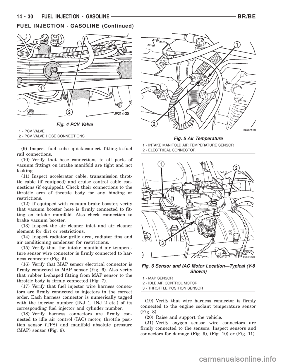
(15) Verify that the intake manifold air tempera-
ture sensor wire connector is firmly connected to har-
ness connector (Fig. 5).
(16) Verify that MAP sensor electrical connector is
firmly connected to MAP sensor (Fig. 6). Also verify
that rubber L-shaped fitting from MAP sensor to the
throttle body is firmly connected (Fig. 7).
(17) Verify that fuel injector wire harness connec-
tors are firmly connected to injectors in the correct
order. Each harness connector is numerically tagged
with the injector number (INJ 1, INJ 2 etc.) of its
corresponding fuel injector and cylinder number.
(18) Verify harness connectors are firmly con-
nected to idle air control (IAC) motor, throttle posi-
tion sensor (TPS) and manifold absolute pressure
(MAP) sensor (Fig. 6).(19) Verify that wire harness connector is firmly
connected to the engine coolant temperature sensor
(Fig. 8).
(20) Raise and support the vehicle.
(21) Verify oxygen sensor wire connectors are
firmly connected to the sensors. Inspect sensors and
connectors for damage (Fig. 9), (Fig. 10) or (Fig. 11).
Fig. 4 PCV Valve
1 - P C V VA LV E
2 - PCV VALVE HOSE CONNECTIONS
Fig. 5 Air Temperature
1 - INTAKE MANIFOLD AIR TEMPERATURE SENSOR
2 - ELECTRICAL CONNECTOR
Fig. 6 Sensor and IAC Motor LocationÐTypical (V-8
Shown)
1 - MAP SENSOR
2 - IDLE AIR CONTROL MOTOR
3 - THROTTLE POSITION SENSOR
14 - 30 FUEL INJECTION - GASOLINEBR/BE
FUEL INJECTION - GASOLINE (Continued)
Page 1332 of 2255
(11) Inspect accelerator cable, transmission throt-
tle cable (if equipped) and cruise control cable con-
nections (if equipped). Check their connections to the
throttle arm of throttle body for any binding or
restrictions.
(12) If equipped with vacuum brake booster, verify
that vacuum booster hose is firmly connected to fit-
ting on intake manifold. Also check connection to
brake vacuum booster.
(13) Inspect the air cleaner inlet and air cleaner
element for dirt or restrictions.
(14) Inspect radiator grille area, radiator fins and
air conditioning condenser for restrictions.
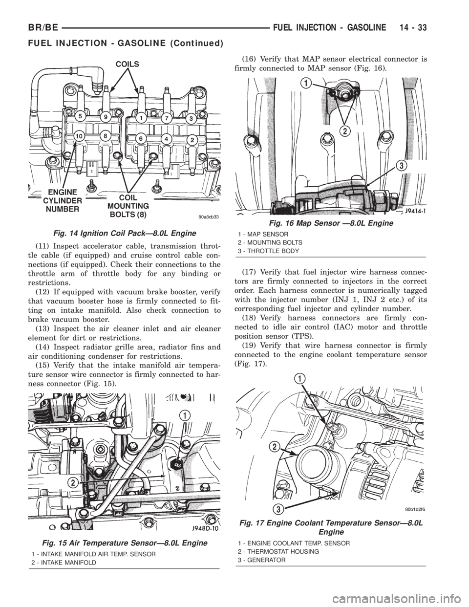
(15) Verify that the intake manifold air tempera-
ture sensor wire connector is firmly connected to har-
ness connector (Fig. 15).(16) Verify that MAP sensor electrical connector is
firmly connected to MAP sensor (Fig. 16).
(17) Verify that fuel injector wire harness connec-
tors are firmly connected to injectors in the correct
order. Each harness connector is numerically tagged
with the injector number (INJ 1, INJ 2 etc.) of its
corresponding fuel injector and cylinder number.
(18) Verify harness connectors are firmly con-
nected to idle air control (IAC) motor and throttle
position sensor (TPS).
(19) Verify that wire harness connector is firmly
connected to the engine coolant temperature sensor
(Fig. 17).
Fig. 14 Ignition Coil PackÐ8.0L Engine
Fig. 15 Air Temperature SensorÐ8.0L Engine
1 - INTAKE MANIFOLD AIR TEMP. SENSOR
2 - INTAKE MANIFOLD
Fig. 16 Map Sensor Ð8.0L Engine
1 - MAP SENSOR
2 - MOUNTING BOLTS
3 - THROTTLE BODY
Fig. 17 Engine Coolant Temperature SensorÐ8.0L
Engine
1 - ENGINE COOLANT TEMP. SENSOR
2 - THERMOSTAT HOUSING
3 - GENERATOR
BR/BEFUEL INJECTION - GASOLINE 14 - 33
FUEL INJECTION - GASOLINE (Continued)
Page 2188 of 2255
(M)Malfunction Indicator Lamp (MIL) illuminated during engine operation if this DTC was recorded
(depending if required by CARB and/or EPA). MIL is displayed as an engine icon on instrument panel.
(G)Generator lamp illuminated
Generic Scan
Tool P-CodeDRB Scan Tool Display Brief Description of DTC
P0509 (M) IAC Motor Sense Circuit High
P0521 Oil Pressure Switch Rationality
P0522 Oil Pressure Voltage Too Low Oil pressure sending unit (sensor) voltage input below the
minimum acceptable voltage.
P0523 Oil Pressure Voltage Too High Oil pressure sending unit (sensor) voltage input above the
maximum acceptable voltage.
P0524 Oil Pressure Too Low Engine oil pressure is low. Engine power derated.
P0545 A/C Clutch Relay Circuit Problem detected in air conditioning clutch relay control
circuit.
P0551 Power Steering Switch Failure Incorrect input state detected for the power steering switch
circuit. PL: High pressure seen at high speed.
P0562 Charging System Voltage Too Low Supply voltage sensed at ECM too low.
P0563 Charging System Voltage Too High Supply voltage sensed at ECM too high.
P0572 Brake Switch Input #1 Signal Missing
P0573 Brake Switch Input #2 Signal Missing
P0575 Cruise Control Switch Voltage Low
P0576 Cruise Control Switch Voltage High
P0577 Cruise Control Switch Voltage High
P0600 PCM Failure SPI Communications No communication detected between co-processors in the
control module.
P0601 (M) Internal Controller Failure Internal control module fault condition (check sum) detected.
P0602 (M) ECM Fueling Calibration Error ECM Internal fault condition detected.
P0604 RAM Check Failure Transmission control module RAM self test fault detected.
-Aisin transmission
P0605 ROM Check Falure Transmission control module ROM self test fault detected
-Aisin transmission
P0606 (M) ECM Failure ECM Internal fault condition detected.
P0615 Starter Relay Control Circuit An open or shorted condition detected in the starter relay
control circuit.
P0622 (G) Generator Field Not Switching Properly An open or shorted condition detected in the generator field
control circuit.
P0645 A/C Clutch Relay Circuit An open or shorted condition detected in the A/C clutch relay
control circuit.
P0700 EATX Controller DTC Present This SBEC III or JTEC DTC indicates that the EATX or Aisin
controller has an active fault and has illuminated the MIL via
a CCD (EATX) or SCI (Aisin) message. The specific fault
must be acquired from the EATX via CCD or from the Aisin
via ISO-9141.
P0703 Brake Switch Stuck Pressed or
ReleasedIncorrect input state detected in the brake switch circuit.
(Changed from P1595)
P0703 Brake Switch Sense Circuit
BR/BEEMISSIONS CONTROL 25 - 9
EMISSIONS CONTROL (Continued)
Page 2233 of 2255
HIGH MOUNTED STOP LAMP -
INSTALLATION, CENTER................8L-6
HIGH MOUNTED STOP LAMP -
REMOVAL, CENTER....................8L-6
HIGH MOUNTED STOP LAMP UNIT -
INSTALLATION, CENTER................8L-6
HIGH MOUNTED STOP LAMP UNIT -
REMOVAL, CENTER....................8L-6
HIGH PRESSURE FUEL LINES -
DESCRIPTION.......................14-78
HIGH PRESSURE FUEL LINES -
OPERATION.........................14-78
HIGH PRESSURE RELIEF VALVE -
DESCRIPTION.......................24-46
HIGH PRESSURE RELIEF VALVE -
OPERATION.........................24-47
HIGH PRESSURE SWITCH -
DESCRIPTION, A/C...................24-20
HIGH PRESSURE SWITCH - DIAGNOSIS
AND TESTING, A/C...................24-20
HIGH PRESSURE SWITCH -
INSTALLATION, A/C...................24-20
HIGH PRESSURE SWITCH - OPERATION,
A/C................................24-20
HIGH PRESSURE SWITCH - REMOVAL,
A/C................................24-20
HIGH SPEEDS - DESCRIPTION, TIRE
PRESSURE..........................22-7
HIGH-PRESSURE FUEL LINE LEAKS -
DIAGNOSIS AND TESTING.............14-78
HINGE - INSTALLATION.....23-100,23-72,23-80
HINGE - REMOVAL........23-100,23-72,23-79
HITCH - INSTALLATION, TRAILER.........13-11
HITCH - REMOVAL, TRAILER...........13-11
HOISTING - STANDARD PROCEDURE.......0-9
HOLDDOWN - DESCRIPTION, BATTERY . . . 8F-17
HOLDDOWN - INSTALLATION, BATTERY . . . 8F-18
HOLDDOWN - OPERATION, BATTERY.....8F-17
HOLDDOWN - REMOVAL, BATTERY......8F-17
HOLDER - INSTALLATION, CUP........23-110
HOLDER - REMOVAL, CUP............23-109
HOLE REPAIR - DESCRIPTION,
THREADED........................Intro.-9
HONING - STANDARD PROCEDURE,
CYLINDER BORE..................9-11,9-65
HOOD - INSTALLATION...............23-101
HOOD - REMOVAL...................23-101
HOOK - INSTALLATION, COAT..........23-125
HOOK - INSTALLATION, FRONT TOW.....13-10
HOOK - REMOVAL, COAT.............23-124
HOOK - REMOVAL, FRONT TOW.........13-10
HORN - DESCRIPTION.............8H-1,8H-2
HORN - DIAGNOSIS AND TESTING.......8H-2
HORN - INSTALLATION.................8H-3
HORN - OPERATION...............8H-1,8H-2
HORN - REMOVAL....................8H-2
HORN RELAY - DESCRIPTION.......8W-97-12
HORN RELAY - DESCRIPTION...........8H-3
HORN RELAY - DIAGNOSIS AND
TESTING........................8W-97-12
HORN RELAY - DIAGNOSIS AND
TESTING............................8H-3
HORN RELAY - INSTALLATION.......8W-97-12
HORN RELAY - INSTALLATION...........8H-4
HORN RELAY - OPERATION.............8H-3
HORN RELAY - REMOVAL..........8W-97-12
HORN RELAY - REMOVAL..............8H-4
HORN SWITCH - DESCRIPTION..........8H-4
HORN SWITCH - DIAGNOSIS AND
TESTING............................8H-5
HORN SWITCH - OPERATION............8H-5
HORN SWITCH - REMOVAL.............8H-5
HOSE CLAMPS - DESCRIPTION...........7-4
HOSE CLAMPS - OPERATION.............7-4
HOSE WITH AIR CONDITIONING -
INSTALLATION, WATER PUMP BYPASS....7-76
HOSE WITH AIR CONDITIONING -
REMOVAL, WATER PUMP BYPASS........7-73
HOSE WITHOUT AIR CONDITIONING -
INSTALLATION, WATER PUMP BYPASS....7-77
HOSE WITHOUT AIR CONDITIONING -
REMOVAL, WATER PUMP BYPASS........7-76
HOSES - PRESSURE - DESCRIPTION
.....19-39
HOSES - PRESSURE - OPERATION
.......19-39
HOSES - RETURN - DESCRIPTION
.......19-39
HOSES - RETURN - OPERATION
.........19-39
HOSES/LINES/TUBES PRECAUTIONS -
CAUTION, REFRIGERANT
..............24-43HOSES/TUBES - DESCRIPTION, WASHER . . 8R-8
HOSES/TUBES - OPERATION, WASHER....8R-8
HOUSING - ASSEMBLY, HVAC...........24-36
HOUSING - DIAGNOSIS AND TESTING,
CLUTCH..............................6-9
HOUSING - DISASSEMBLY, HVAC........24-35
HOUSING - INSTALLATION, CLUTCH......6-11
HOUSING - INSTALLATION, GEAR........9-188
HOUSING - INSTALLATION, HVAC........24-36
HOUSING - REMOVAL, CLUTCH..........6-11
HOUSING - REMOVAL, GEAR...........9-187
HOUSING - REMOVAL, HVAC...........24-34
HOUSING BUSHING - INSTALLATION,
EXTENSION..................21-156,21-326
HOUSING BUSHING - REMOVAL,
EXTENSION..................21-156,21-326
HOUSING BUSHING AND SEAL -
INSTALLATION, EXTENSION.....21-460,21-497
HOUSING BUSHING AND SEAL -
REMOVAL, EXTENSION.........21-460,21-497
HOUSING COVER - INSTALLATION, GEAR . 9-190
HOUSING COVER - REMOVAL, GEAR.....9-189
HOUSING FLUID LEAK - DIAGNOSIS AND
TESTING, CONVERTER.........21-101,21-273
HOUSING INLET BAFFLE -
INSTALLATION, HVAC.................24-36
HOUSING INLET BAFFLE - REMOVAL,
HVAC..............................24-35
HOUSING PLUG - INSTALLATION,
STEERING GEAR.......................19-30
HOUSING PLUG - REMOVAL, STEERING
GEAR..............................19-29
HOUSING SEAL - INSTALLATION,
EXTENSION..................21-156,21-327
HOUSING SEAL - NV4500 -
INSTALLATION, ADAPTER..............21-42
HOUSING SEAL - NV4500 -
INSTALLATION, EXTENSION............21-42
HOUSING SEAL - NV4500 - REMOVAL,
ADAPTER...........................21-42
HOUSING SEAL - NV4500 - REMOVAL,
EXTENSION.........................21-42
HOUSING SEAL - NV5600 -
INSTALLATION, ADAPTER..............21-85
HOUSING SEAL - NV5600 -
INSTALLATION, EXTENSION............21-85
HOUSING SEAL - NV5600 - REMOVAL,
ADAPTER...........................21-85
HOUSING SEAL - NV5600 - REMOVAL,
EXTENSION.........................21-85
HOUSING SEAL - REMOVAL,
EXTENSION..................21-156,21-326
HUB / BEARING - INSTALLATION......2-17,2-9
HUB / BEARING - REMOVAL..........2-16,2-9
HVAC HOUSING - ASSEMBLY...........24-36
HVAC HOUSING - DISASSEMBLY........24-35
HVAC HOUSING - INSTALLATION........24-36
HVAC HOUSING - REMOVAL............24-34
HVAC HOUSING INLET BAFFLE -
INSTALLATION.......................24-36
HVAC HOUSING INLET BAFFLE -
REMOVAL..........................24-35
HVAC SYSTEM AIRFLOW - DESCRIPTION . 24-30
HYDRAULIC BOOSTER - DIAGNOSIS
AND TESTING........................5-18
HYDRAULIC LIFTERS - CLEANING
....9-37,9-92
HYDRAULIC LIFTERS - INSTALLATION
. 9-37,9-92
HYDRAULIC LIFTERS - REMOVAL
....9-37,9-92
HYDRAULIC PRESSURE TEST -
DIAGNOSIS AND TESTING
.......21-270,21-98
HYDRAULIC SCHEMATICS, SCHEMATICS
AND DIAGRAMS
..............21-132,21-302
HYDRAULIC TAPPETS - DIAGNOSIS AND
TESTING
........................9-36,9-91
HYDRAULIC/MECHANICAL -
DESCRIPTION
.........................5-4
HYDRAULIC/MECHANICAL - WARNING
.....5-4
HYDROMETER TEST - STANDARD
PROCEDURE
........................8F-11
HYDROSTATIC LOCK - STANDARD
PROCEDURE
................9-11,9-122,9-66
IDENTIFICATION - DESCRIPTION,
FASTENER
.........................Intro.-6
IDENTIFICATION AND INFORMATION -
DESCRIPTION, SECTION
.............8W-01-6
IDENTIFICATION LAMP - INSTALLATION,
OUTBOARD
.........................8L-29IDENTIFICATION LAMP - REMOVAL,
OUTBOARD.........................8L-28
IDENTIFICATION NUMBER -
DESCRIPTION, VEHICLE..............Intro.-1
IDENTIFICATION PLATE - DESCRIPTION,
EQUIPMENT.......................Intro.-3
IDLE AIR CONTROL MOTOR -
DESCRIPTION.......................14-40
IDLE AIR CONTROL MOTOR -
OPERATION.........................14-40
IGNITION - SPECIFICATIONS, TORQUE.....8I-2
IGNITION CIRCUIT SENSE -
DESCRIPTION.......................8E-17
IGNITION CIRCUIT SENSE - OPERATION . . 8E-19
IGNITION COIL RESISTANCE, 5.9L
ENGINES............................8I-3
IGNITION COIL RESISTANCE, 8.0L V-10
ENGINE..............................8I-4
IGNITION SWITCH - DESCRIPTION.......19-11
IGNITION SWITCH - DESCRIPTION,
KEY-IN..............................19-9
IGNITION SWITCH - DIAGNOSIS AND
TESTING...........................19-11
IGNITION SWITCH - INSTALLATION......19-12
IGNITION SWITCH - OPERATION........19-11
IGNITION SWITCH - REMOVAL..........19-12
IGNITION SWITCH AND KEY LOCK
CYLINDER - DIAGNOSIS AND TESTING....19-9
IGNITION TIMING, SPECIFICATIONS.......8I-4
IGNITION-OFF DRAW TEST - STANDARD
PROCEDURE........................8F-13
INDEPENDENT FRONT SUSPENSION,
SPECIAL TOOLS.......................2-9
INDICATOR - DESCRIPTION, ABS........8J-14
INDICATOR - DESCRIPTION, AIRBAG.....8J-15
INDICATOR - DESCRIPTION, BRAKE/
PARK BRAKE........................8J-15
INDICATOR - DESCRIPTION, CHECK
GAUGES............................8J-17
INDICATOR - DESCRIPTION, CRUISE.....8J-18
INDICATOR - DESCRIPTION, GEAR
SELECTOR..........................8J-20
INDICATOR - DESCRIPTION, HIGH BEAM . . 8J-21
INDICATOR - DESCRIPTION, LOW FUEL . . . 8J-22
INDICATOR - DESCRIPTION, OVERDRIVE
OFF ...............................8J-26
INDICATOR - DESCRIPTION, SEATBELT . . . 8J-27
INDICATOR - DESCRIPTION, SERVICE
REMINDER..........................8J-27
INDICATOR - DESCRIPTION, TRANS
OVERTEMP.........................8J-31
INDICATOR - DESCRIPTION, TURN
SIGNAL............................8J-32
INDICATOR - DESCRIPTION, UPSHIFT....8J-32
INDICATOR - DESCRIPTION, VTSS........8Q-3
INDICATOR - DESCRIPTION, WAIT-TO-
START .............................8J-34
INDICATOR - DESCRIPTION, WASHER
FLUID..............................8J-35
INDICATOR - DESCRIPTION, WATER-IN-
FUEL..............................8J-36
INDICATOR - DIAGNOSIS AND TESTING,
BRAKE.............................8J-16
INDICATOR - DIAGNOSIS AND TESTING,
FOUR-WHEEL DRIVE..................8J-29
INDICATOR - DIAGNOSIS AND TESTING,
HIGH BEAM.........................8J-21
INDICATOR - DIAGNOSIS AND TESTING,
TURN SIGNAL
.......................8J-32
INDICATOR - DIAGNOSIS AND TESTING,
VTSS
...............................8Q-4
INDICATOR - DIAGNOSIS AND TESTING,
WASHER FLUID
......................8J-35
INDICATOR - OPERATION, ABS
..........8J-14
INDICATOR - OPERATION, AIRBAG
.......8J-15
INDICATOR - OPERATION, BRAKE/PARK
BRAKE
.............................8J-15
INDICATOR - OPERATION, CHECK
GAUGES
............................8J-17
INDICATOR - OPERATION, CRUISE
.......8J-18
INDICATOR - OPERATION, GEAR
SELECTOR
..........................8J-21
INDICATOR - OPERATION, HIGH BEAM
....8J-21
INDICATOR - OPERATION, LOW FUEL
.....8J-22
INDICATOR - OPERATION, OVERDRIVE
OFF
...............................8J-26
INDICATOR - OPERATION, SEATBELT
.....8J-27
16 INDEXBR/BE
Description Group-Page Description Group-Page Description Group-Page