2002 DODGE RAM oil pressure
[x] Cancel search: oil pressurePage 1406 of 2255
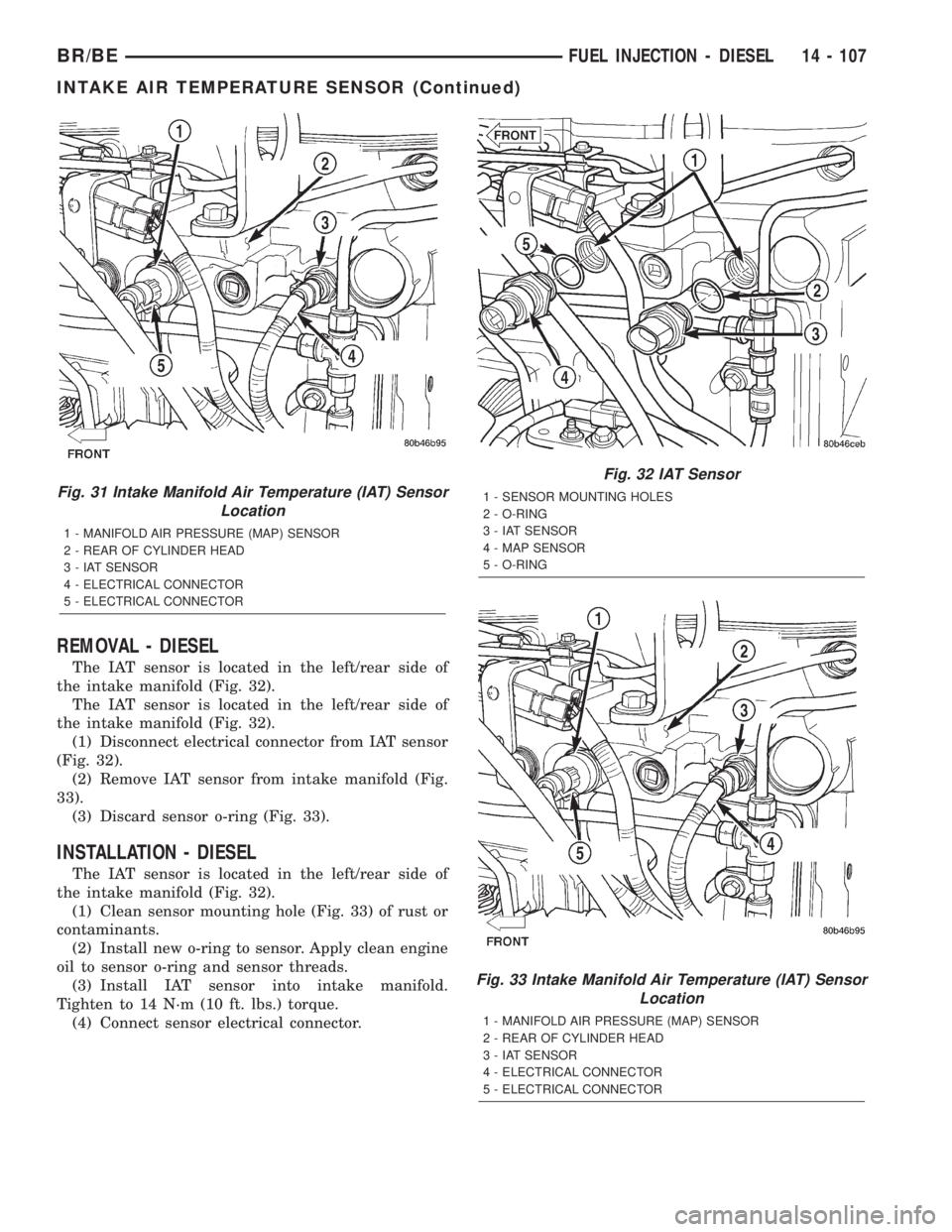
REMOVAL - DIESEL
The IAT sensor is located in the left/rear side of
the intake manifold (Fig. 32).
The IAT sensor is located in the left/rear side of
the intake manifold (Fig. 32).
(1) Disconnect electrical connector from IAT sensor
(Fig. 32).
(2) Remove IAT sensor from intake manifold (Fig.
33).
(3) Discard sensor o-ring (Fig. 33).
INSTALLATION - DIESEL
The IAT sensor is located in the left/rear side of
the intake manifold (Fig. 32).
(1) Clean sensor mounting hole (Fig. 33) of rust or
contaminants.
(2) Install new o-ring to sensor. Apply clean engine
oil to sensor o-ring and sensor threads.
(3) Install IAT sensor into intake manifold.
Tighten to 14 N´m (10 ft. lbs.) torque.
(4) Connect sensor electrical connector.
Fig. 31 Intake Manifold Air Temperature (IAT) Sensor
Location
1 - MANIFOLD AIR PRESSURE (MAP) SENSOR
2 - REAR OF CYLINDER HEAD
3 - IAT SENSOR
4 - ELECTRICAL CONNECTOR
5 - ELECTRICAL CONNECTOR
Fig. 32 IAT Sensor
1 - SENSOR MOUNTING HOLES
2 - O-RING
3 - IAT SENSOR
4 - MAP SENSOR
5 - O-RING
Fig. 33 Intake Manifold Air Temperature (IAT) Sensor
Location
1 - MANIFOLD AIR PRESSURE (MAP) SENSOR
2 - REAR OF CYLINDER HEAD
3 - IAT SENSOR
4 - ELECTRICAL CONNECTOR
5 - ELECTRICAL CONNECTOR
BR/BEFUEL INJECTION - DIESEL 14 - 107
INTAKE AIR TEMPERATURE SENSOR (Continued)
Page 1407 of 2255
MAP SENSOR
DESCRIPTION - DIESEL
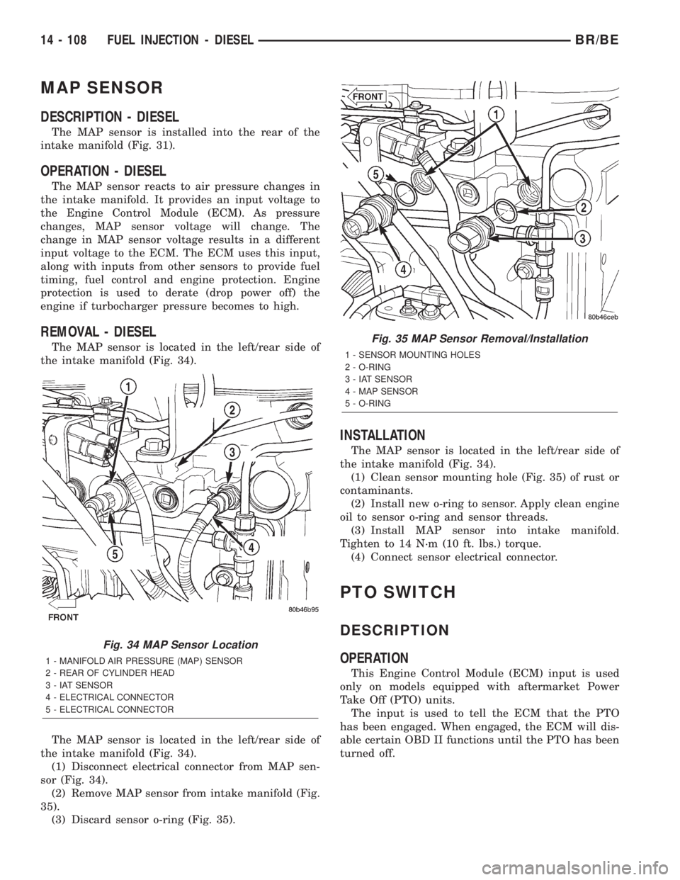
The MAP sensor is installed into the rear of the
intake manifold (Fig. 31).
OPERATION - DIESEL
The MAP sensor reacts to air pressure changes in
the intake manifold. It provides an input voltage to
the Engine Control Module (ECM). As pressure
changes, MAP sensor voltage will change. The
change in MAP sensor voltage results in a different
input voltage to the ECM. The ECM uses this input,
along with inputs from other sensors to provide fuel
timing, fuel control and engine protection. Engine
protection is used to derate (drop power off) the
engine if turbocharger pressure becomes to high.
REMOVAL - DIESEL
The MAP sensor is located in the left/rear side of
the intake manifold (Fig. 34).
The MAP sensor is located in the left/rear side of
the intake manifold (Fig. 34).
(1) Disconnect electrical connector from MAP sen-
sor (Fig. 34).
(2) Remove MAP sensor from intake manifold (Fig.
35).
(3) Discard sensor o-ring (Fig. 35).
INSTALLATION
The MAP sensor is located in the left/rear side of
the intake manifold (Fig. 34).
(1) Clean sensor mounting hole (Fig. 35) of rust or
contaminants.
(2) Install new o-ring to sensor. Apply clean engine
oil to sensor o-ring and sensor threads.
(3) Install MAP sensor into intake manifold.
Tighten to 14 N´m (10 ft. lbs.) torque.
(4) Connect sensor electrical connector.
PTO SWITCH
DESCRIPTION
OPERATION
This Engine Control Module (ECM) input is used
only on models equipped with aftermarket Power
Take Off (PTO) units.
The input is used to tell the ECM that the PTO
has been engaged. When engaged, the ECM will dis-
able certain OBD II functions until the PTO has been
turned off.
Fig. 34 MAP Sensor Location
1 - MANIFOLD AIR PRESSURE (MAP) SENSOR
2 - REAR OF CYLINDER HEAD
3 - IAT SENSOR
4 - ELECTRICAL CONNECTOR
5 - ELECTRICAL CONNECTOR
Fig. 35 MAP Sensor Removal/Installation
1 - SENSOR MOUNTING HOLES
2 - O-RING
3 - IAT SENSOR
4 - MAP SENSOR
5 - O-RING
14 - 108 FUEL INJECTION - DIESELBR/BE
Page 1410 of 2255
STEERING
TABLE OF CONTENTS
page page
STEERING
DESCRIPTION..........................1
OPERATION............................1
DIAGNOSIS AND TESTING
DIAGNOSIS AND TESTING - POWER
STEERING SYSTEM....................2
DIAGNOSIS AND TESTING - POWER
STEERING FLOW AND PRESSURE........4COLUMN...............................6
GEAR.................................16
PUMP.................................33
LINKAGE - 2WD.........................40
LINKAGE - 4WD.........................42
STEERING
DESCRIPTION
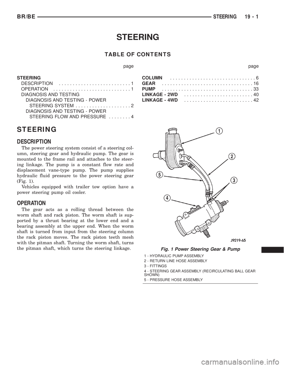
The power steering system consist of a steering col-
umn, steering gear and hydraulic pump. The gear is
mounted to the frame rail and attaches to the steer-
ing linkage. The pump is a constant flow rate and
displacement vane-type pump. The pump supplies
hydraulic fluid pressure to the power steering gear
(Fig. 1).
Vehicles equipped with trailer tow option have a
power steering pump oil cooler.
OPERATION
The gear acts as a rolling thread between the
worm shaft and rack piston. The worm shaft is sup-
ported by a thrust bearing at the lower end and a
bearing assembly at the upper end. When the worm
shaft is turned from input from the steering column
the rack piston moves. The rack piston teeth mesh
with the pitman shaft. Turning the worm shaft, turns
the pitman shaft, which turns the steering linkage.
Fig. 1 Power Steering Gear & Pump
1 - HYDRAULIC PUMP ASSEMBLY
2 - RETURN LINE HOSE ASSEMBLY
3 - FITTINGS
4 - STEERING GEAR ASSEMBLY (RECIRCULATING BALL GEAR
SHOWN)
5 - PRESSURE HOSE ASSEMBLY
BR/BESTEERING 19 - 1
Page 1442 of 2255
PUMP
TABLE OF CONTENTS
page page
PUMP
DESCRIPTION.........................33
OPERATION...........................33
DIAGNOSIS AND TESTING - PUMP LEAKAGE . 33
STANDARD PROCEDURE
STANDARD PROCEDURE - POWER
STEERING PUMP - INITIAL OPERATION....33
STANDARD PROCEDURE - FLUSHING
POWER STEERING SYSTEM............34
REMOVAL
REMOVAL - GASOLINE ENGINE..........35
REMOVAL - DIESEL ENGINE............36
INSTALLATION
INSTALLATION - GASOLINE ENGINE......37INSTALLATION - DIESEL ENGINE.........37
SPECIAL TOOLS
POWER STEERING PUMP..............38
PULLEY
REMOVAL.............................38
INSTALLATION.........................39
HOSES - PRESSURE
DESCRIPTION.........................39
OPERATION...........................39
HOSES - RETURN
DESCRIPTION.........................39
OPERATION...........................39
PUMP
DESCRIPTION
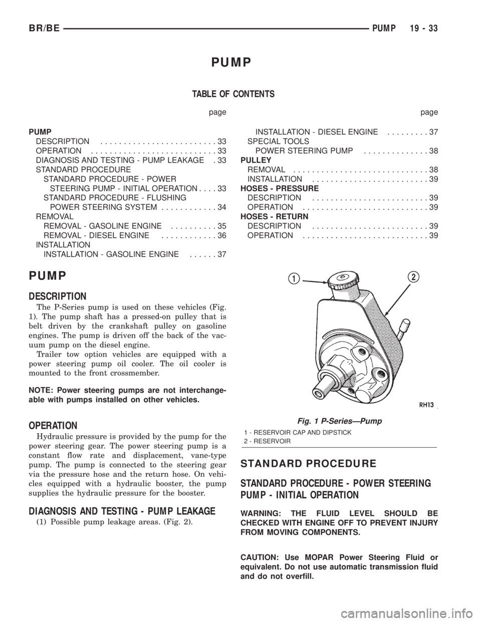
The P-Series pump is used on these vehicles (Fig.
1). The pump shaft has a pressed-on pulley that is
belt driven by the crankshaft pulley on gasoline
engines. The pump is driven off the back of the vac-
uum pump on the diesel engine.
Trailer tow option vehicles are equipped with a
power steering pump oil cooler. The oil cooler is
mounted to the front crossmember.
NOTE: Power steering pumps are not interchange-
able with pumps installed on other vehicles.
OPERATION
Hydraulic pressure is provided by the pump for the
power steering gear. The power steering pump is a
constant flow rate and displacement, vane-type
pump. The pump is connected to the steering gear
via the pressure hose and the return hose. On vehi-
cles equipped with a hydraulic booster, the pump
supplies the hydraulic pressure for the booster.
DIAGNOSIS AND TESTING - PUMP LEAKAGE
(1) Possible pump leakage areas. (Fig. 2).
STANDARD PROCEDURE
STANDARD PROCEDURE - POWER STEERING
PUMP - INITIAL OPERATION
WARNING: THE FLUID LEVEL SHOULD BE
CHECKED WITH ENGINE OFF TO PREVENT INJURY
FROM MOVING COMPONENTS.
CAUTION: Use MOPAR Power Steering Fluid or
equivalent. Do not use automatic transmission fluid
and do not overfill.
Fig. 1 P-SeriesÐPump
1 - RESERVOIR CAP AND DIPSTICK
2 - RESERVOIR
BR/BEPUMP 19 - 33
Page 1445 of 2255
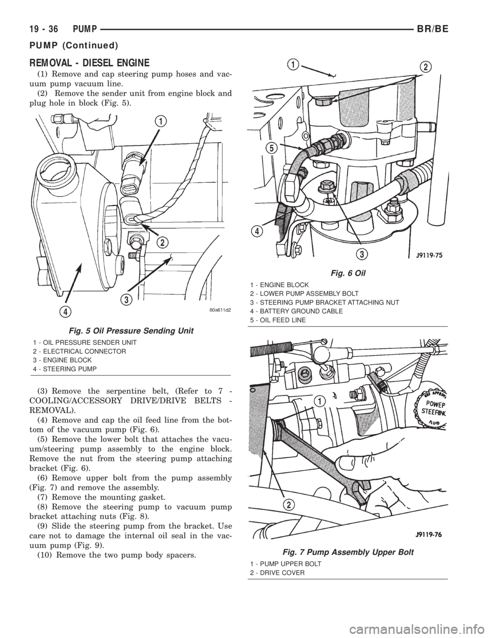
REMOVAL - DIESEL ENGINE
(1) Remove and cap steering pump hoses and vac-
uum pump vacuum line.
(2) Remove the sender unit from engine block and
plug hole in block (Fig. 5).
(3) Remove the serpentine belt, (Refer to 7 -
COOLING/ACCESSORY DRIVE/DRIVE BELTS -
REMOVAL).
(4) Remove and cap the oil feed line from the bot-
tom of the vacuum pump (Fig. 6).
(5) Remove the lower bolt that attaches the vacu-
um/steering pump assembly to the engine block.
Remove the nut from the steering pump attaching
bracket (Fig. 6).
(6) Remove upper bolt from the pump assembly
(Fig. 7) and remove the assembly.
(7) Remove the mounting gasket.
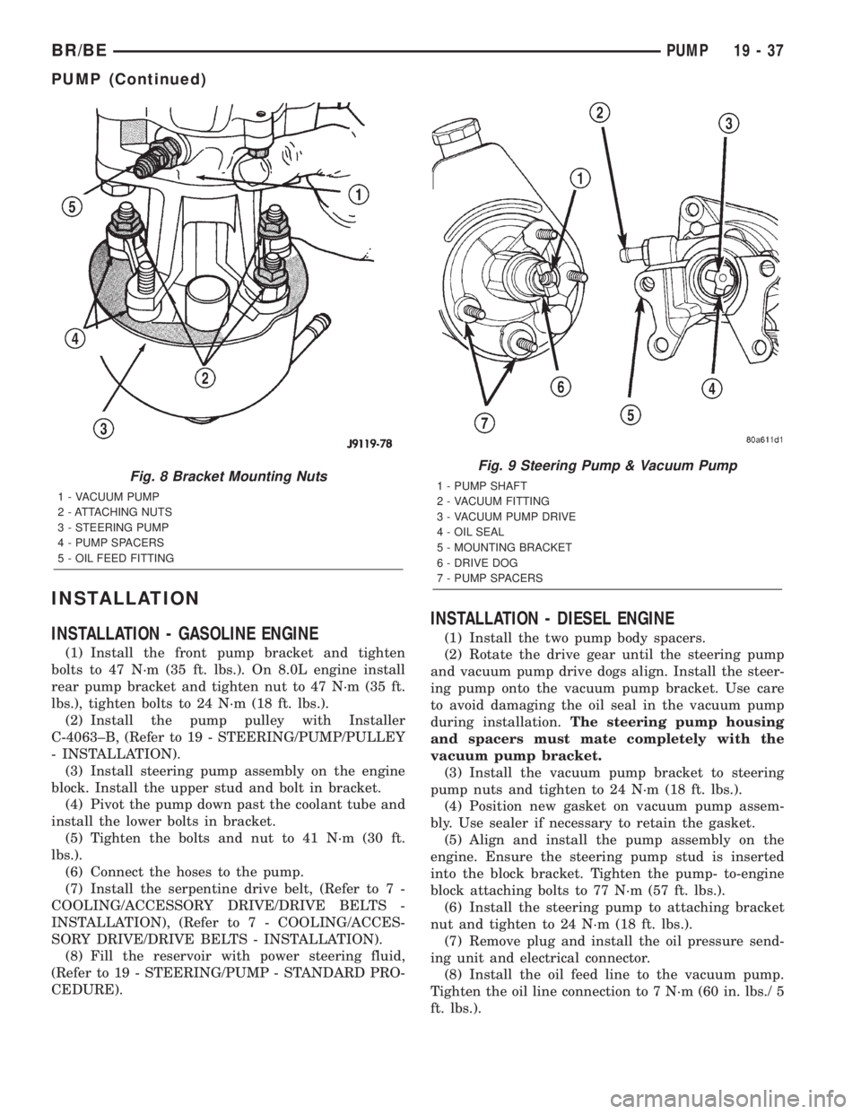
(8) Remove the steering pump to vacuum pump
bracket attaching nuts (Fig. 8).
(9) Slide the steering pump from the bracket. Use
care not to damage the internal oil seal in the vac-
uum pump (Fig. 9).
(10) Remove the two pump body spacers.
Fig. 5 Oil Pressure Sending Unit
1 - OIL PRESSURE SENDER UNIT
2 - ELECTRICAL CONNECTOR
3 - ENGINE BLOCK
4 - STEERING PUMP
Fig. 6 Oil
1 - ENGINE BLOCK
2 - LOWER PUMP ASSEMBLY BOLT
3 - STEERING PUMP BRACKET ATTACHING NUT
4 - BATTERY GROUND CABLE
5 - OIL FEED LINE
Fig. 7 Pump Assembly Upper Bolt
1 - PUMP UPPER BOLT
2 - DRIVE COVER
19 - 36 PUMPBR/BE
PUMP (Continued)
Page 1446 of 2255
INSTALLATION
INSTALLATION - GASOLINE ENGINE
(1) Install the front pump bracket and tighten
bolts to 47 N´m (35 ft. lbs.). On 8.0L engine install
rear pump bracket and tighten nut to 47 N´m (35 ft.
lbs.), tighten bolts to 24 N´m (18 ft. lbs.).
(2) Install the pump pulley with Installer
C-4063±B, (Refer to 19 - STEERING/PUMP/PULLEY
- INSTALLATION).
(3) Install steering pump assembly on the engine
block. Install the upper stud and bolt in bracket.
(4) Pivot the pump down past the coolant tube and
install the lower bolts in bracket.
(5) Tighten the bolts and nut to 41 N´m (30 ft.
lbs.).
(6) Connect the hoses to the pump.
(7) Install the serpentine drive belt, (Refer to 7 -
COOLING/ACCESSORY DRIVE/DRIVE BELTS -
INSTALLATION), (Refer to 7 - COOLING/ACCES-
SORY DRIVE/DRIVE BELTS - INSTALLATION).
(8) Fill the reservoir with power steering fluid,
(Refer to 19 - STEERING/PUMP - STANDARD PRO-
CEDURE).
INSTALLATION - DIESEL ENGINE
(1) Install the two pump body spacers.
(2) Rotate the drive gear until the steering pump
and vacuum pump drive dogs align. Install the steer-
ing pump onto the vacuum pump bracket. Use care
to avoid damaging the oil seal in the vacuum pump
during installation.The steering pump housing
and spacers must mate completely with the
vacuum pump bracket.
(3) Install the vacuum pump bracket to steering
pump nuts and tighten to 24 N´m (18 ft. lbs.).
(4) Position new gasket on vacuum pump assem-
bly. Use sealer if necessary to retain the gasket.
(5) Align and install the pump assembly on the
engine. Ensure the steering pump stud is inserted
into the block bracket. Tighten the pump- to-engine
block attaching bolts to 77 N´m (57 ft. lbs.).
(6) Install the steering pump to attaching bracket
nut and tighten to 24 N´m (18 ft. lbs.).
(7) Remove plug and install the oil pressure send-
ing unit and electrical connector.
(8) Install the oil feed line to the vacuum pump.
Tighten the oil line connection to 7 N´m (60 in. lbs./ 5
ft. lbs.).
Fig. 8 Bracket Mounting Nuts
1 - VACUUM PUMP
2 - ATTACHING NUTS
3 - STEERING PUMP
4 - PUMP SPACERS
5 - OIL FEED FITTING
Fig. 9 Steering Pump & Vacuum Pump
1 - PUMP SHAFT
2 - VACUUM FITTING
3 - VACUUM PUMP DRIVE
4 - OIL SEAL
5 - MOUNTING BRACKET
6 - DRIVE DOG
7 - PUMP SPACERS
BR/BEPUMP 19 - 37
PUMP (Continued)
Page 1501 of 2255
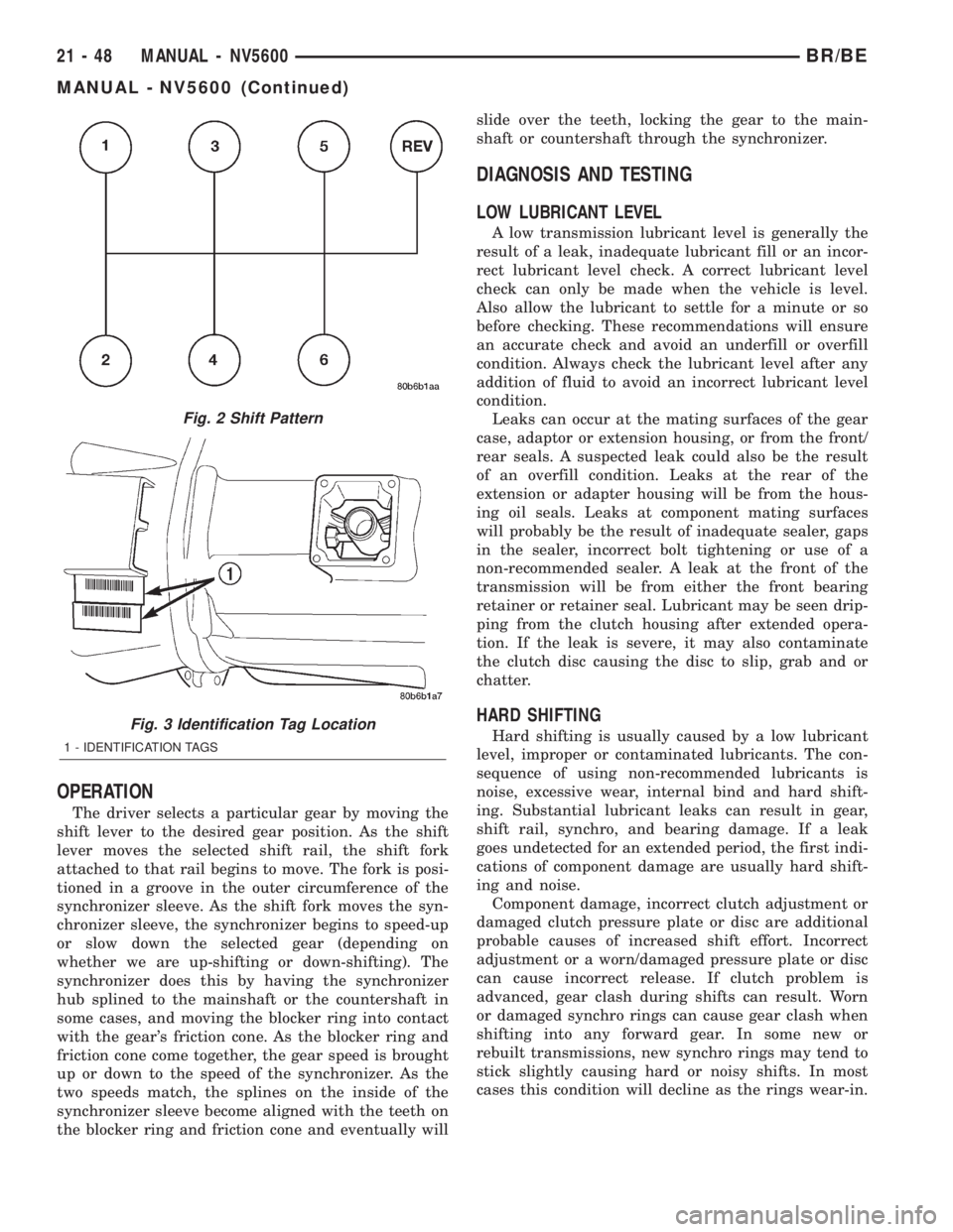
OPERATION
The driver selects a particular gear by moving the
shift lever to the desired gear position. As the shift
lever moves the selected shift rail, the shift fork
attached to that rail begins to move. The fork is posi-
tioned in a groove in the outer circumference of the
synchronizer sleeve. As the shift fork moves the syn-
chronizer sleeve, the synchronizer begins to speed-up
or slow down the selected gear (depending on
whether we are up-shifting or down-shifting). The
synchronizer does this by having the synchronizer
hub splined to the mainshaft or the countershaft in
some cases, and moving the blocker ring into contact
with the gear's friction cone. As the blocker ring and
friction cone come together, the gear speed is brought
up or down to the speed of the synchronizer. As the
two speeds match, the splines on the inside of the
synchronizer sleeve become aligned with the teeth on
the blocker ring and friction cone and eventually willslide over the teeth, locking the gear to the main-
shaft or countershaft through the synchronizer.
DIAGNOSIS AND TESTING
LOW LUBRICANT LEVEL
A low transmission lubricant level is generally the
result of a leak, inadequate lubricant fill or an incor-
rect lubricant level check. A correct lubricant level
check can only be made when the vehicle is level.
Also allow the lubricant to settle for a minute or so
before checking. These recommendations will ensure
an accurate check and avoid an underfill or overfill
condition. Always check the lubricant level after any
addition of fluid to avoid an incorrect lubricant level
condition.
Leaks can occur at the mating surfaces of the gear
case, adaptor or extension housing, or from the front/
rear seals. A suspected leak could also be the result
of an overfill condition. Leaks at the rear of the
extension or adapter housing will be from the hous-
ing oil seals. Leaks at component mating surfaces
will probably be the result of inadequate sealer, gaps
in the sealer, incorrect bolt tightening or use of a
non-recommended sealer. A leak at the front of the
transmission will be from either the front bearing
retainer or retainer seal. Lubricant may be seen drip-
ping from the clutch housing after extended opera-
tion. If the leak is severe, it may also contaminate
the clutch disc causing the disc to slip, grab and or
chatter.
HARD SHIFTING
Hard shifting is usually caused by a low lubricant
level, improper or contaminated lubricants. The con-
sequence of using non-recommended lubricants is
noise, excessive wear, internal bind and hard shift-
ing. Substantial lubricant leaks can result in gear,
shift rail, synchro, and bearing damage. If a leak
goes undetected for an extended period, the first indi-
cations of component damage are usually hard shift-
ing and noise.
Component damage, incorrect clutch adjustment or
damaged clutch pressure plate or disc are additional
probable causes of increased shift effort. Incorrect
adjustment or a worn/damaged pressure plate or disc
can cause incorrect release. If clutch problem is
advanced, gear clash during shifts can result. Worn
or damaged synchro rings can cause gear clash when
shifting into any forward gear. In some new or
rebuilt transmissions, new synchro rings may tend to
stick slightly causing hard or noisy shifts. In most
cases this condition will decline as the rings wear-in.
Fig. 2 Shift Pattern
Fig. 3 Identification Tag Location
1 - IDENTIFICATION TAGS
21 - 48 MANUAL - NV5600BR/BE
MANUAL - NV5600 (Continued)
Page 1540 of 2255
AUTOMATIC TRANSMISSION - 46RE
TABLE OF CONTENTS
page page
AUTOMATIC TRANSMISSION - 46RE
DESCRIPTION.........................89
OPERATION...........................91
DIAGNOSIS AND TESTING
DIAGNOSIS AND TESTING - AUTOMATIC
TRANSMISSION......................96
DIAGNOSIS AND TESTING - PRELIMINARY . 97
DIAGNOSIS AND TESTING - ROAD
TESTING............................97
DIAGNOSIS AND TESTING - HYDRAULIC
PRESSURE TEST.....................98
DIAGNOSIS AND TESTING - AIR TESTING
TRANSMISSION CLUTCH AND BAND
OPERATION........................100
DIAGNOSIS AND TESTING - CONVERTER
HOUSING FLUID LEAK................101
DIAGNOSIS AND TESTING - DIAGNOSIS
CHARTS...........................102
STANDARD PROCEDURE - ALUMINUM
THREAD REPAIR.....................114
REMOVAL............................114
DISASSEMBLY........................115
CLEANING...........................122
INSPECTION.........................122
ASSEMBLY...........................122
INSTALLATION........................130
SCHEMATICS AND DIAGRAMS
HYDRAULIC SCHEMATICS.............132
SPECIFICATIONS
TRANSMISSION.....................144
SPECIAL TOOLS
RE TRANSMISSION..................146
ACCUMULATOR
DESCRIPTION........................149
OPERATION..........................150
INSPECTION.........................150
BANDS
DESCRIPTION........................150
OPERATION..........................151
ADJUSTMENTS
ADJUSTMENT - BANDS...............151
ELECTRONIC GOVERNOR
DESCRIPTION........................152
OPERATION..........................153
REMOVAL............................154
INSTALLATION........................154
EXTENSION HOUSING BUSHING
REMOVAL............................156
INSTALLATION........................156EXTENSION HOUSING SEAL
REMOVAL............................156
INSTALLATION........................156
FLUID AND FILTER
DIAGNOSIS AND TESTING
DIAGNOSIS AND TESTING - EFFECTS OF
INCORRECT FLUID LEVEL.............157
DIAGNOSIS AND TESTING - CAUSES OF
BURNT FLUID.......................157
DIAGNOSIS AND TESTING - FLUID
CONTAMINATION....................157
STANDARD PROCEDURE
STANDARD PROCEDURE - FLUID LEVEL
CHECK............................157
STANDARD PROCEDURE - FLUID AND
FILTER REPLACEMENT...............158
STANDARD PROCEDURE - TRANSMISSION
FILL...............................160
FRONT CLUTCH
DESCRIPTION........................160
OPERATION..........................160
DISASSEMBLY........................161
INSPECTION.........................162
ASSEMBLY...........................162
FRONT SERVO
DESCRIPTION........................164
OPERATION..........................164
DISASSEMBLY........................164
CLEANING...........................164
INSPECTION.........................164
ASSEMBLY...........................164
OIL PUMP
DESCRIPTION........................166
OPERATION..........................166
STANDARD PROCEDURE - OIL PUMP
VOLUME CHECK.....................166
DISASSEMBLY........................167
CLEANING...........................168
INSPECTION.........................168
ASSEMBLY...........................169
OUTPUT SHAFT FRONT BEARING
REMOVAL............................171
INSTALLATION........................171
OUTPUT SHAFT REAR BEARING
REMOVAL............................171
INSTALLATION........................172
OVERDRIVE CLUTCH
DESCRIPTION........................172
OPERATION..........................172
BR/BEAUTOMATIC TRANSMISSION - 46RE 21 - 87