2002 DODGE RAM oil pressure
[x] Cancel search: oil pressurePage 1149 of 2255
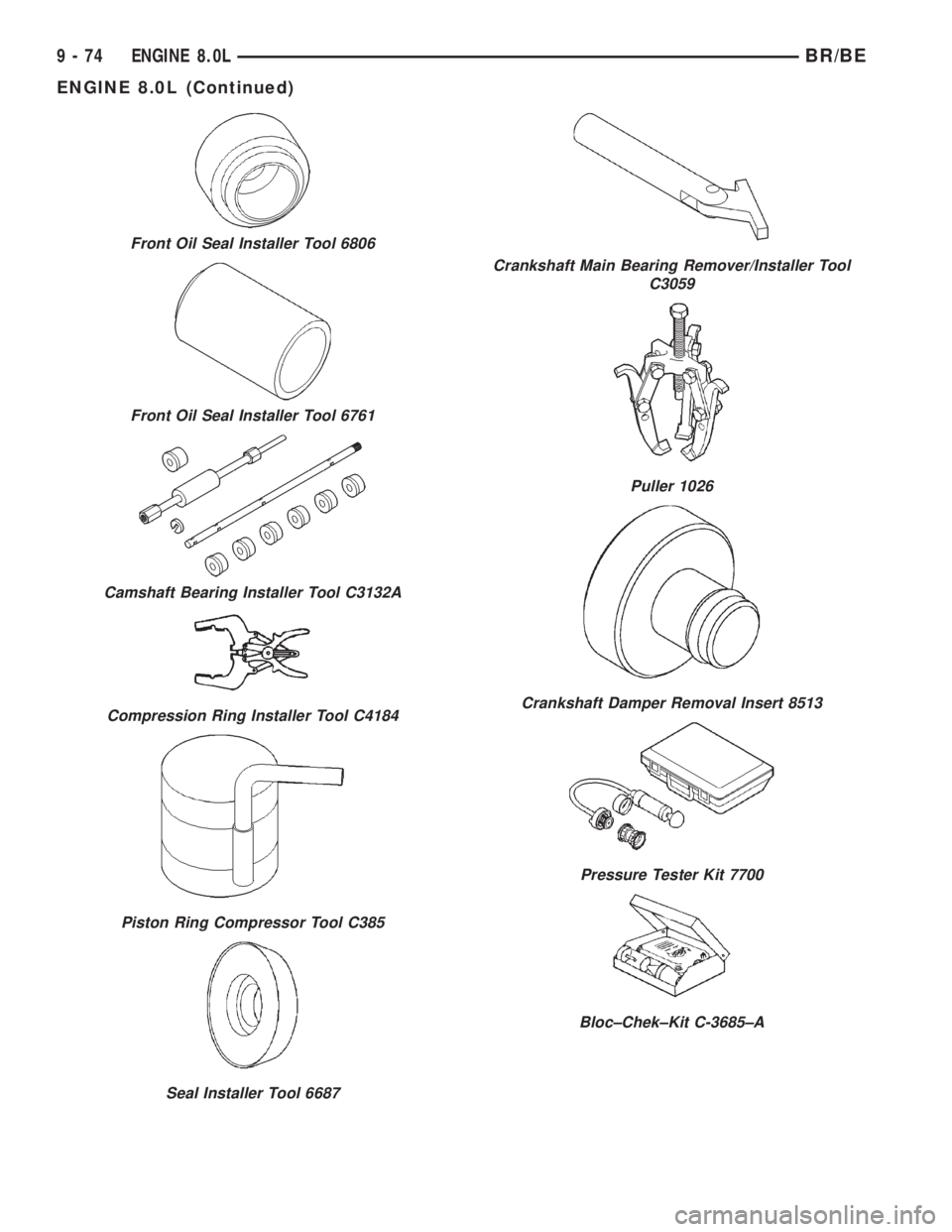
Front Oil Seal Installer Tool 6806
Front Oil Seal Installer Tool 6761
Camshaft Bearing Installer Tool C3132A
Compression Ring Installer Tool C4184
Piston Ring Compressor Tool C385
Seal Installer Tool 6687
Crankshaft Main Bearing Remover/Installer Tool
C3059
Puller 1026
Crankshaft Damper Removal Insert 8513
Pressure Tester Kit 7700
Bloc±Chek±Kit C-3685±A
9 - 74 ENGINE 8.0LBR/BE
ENGINE 8.0L (Continued)
Page 1166 of 2255
(2) Use extream care and clean all gasket resdue
from the retainer.
(3) Apply a small amount of MopartSilicone Rub-
ber Adhesive Sealant to the retainer gasket. Position
the gasket onto the retainer.
(4) Position Special Tool 6687 Seal Guide onto the
crankshaft.
(5) Position the retainer and seal over the guide
and onto the engine block.
(6) Install the retainer mounting bolts. Tighten the
bolts to 22 N´m (16 ft. lbs.).
(7) Install the oil pan (Refer to 9 - ENGINE/LU-
BRICATION/OIL PAN - INSTALLATION).
(8) Install the drive plate / flywheel.
(9) Install the transmission.
(10) Check and verify engine oil level.
(11) Start engine and check for leaks.
HYDRAULIC LIFTERS
DIAGNOSIS AND TESTINGÐHYDRAULIC
TAPPETS
Before disassembling any part of the engine to cor-
rect tappet noise, check the oil pressure. If vehicle
has no oil pressure gauge, install a reliable gauge at
the pressure sending-unit. The pressure should be
between 207-552 kPa (30-80 psi) at 3,000 RPM.
Check the oil level after the engine reaches normal
operating temperature. Allow 5 minutes to stabilize
oil level, check dipstick. The oil level in the pan
should never be above the FULL mark or below the
ADD OIL mark on dipstick. Either of these two con-
ditions could be responsible for noisy tappets.
OIL LEVEL
HIGH
If oil level is above the FULL mark, it is possible
for the connecting rods to dip into the oil. With the
engine running, this condition could create foam in
the oil pan. Foam in oil pan would be fed to the
hydraulic tappets by the oil pump causing them to
lose length and allow valves to seat noisily.
LOW
Low oil level may allow oil pump to take in air.
When air is fed to the tappets, they lose length,
which allows valves to seat noisily. Any leaks on
intake side of oil pump through which air can be
drawn will create the same tappet action. Check the
lubrication system from the intake strainer to the
pump cover, including the relief valve retainer cap.
When tappet noise is due to aeration, it may be
intermittent or constant, and usually more than one
tappet will be noisy. When oil level and leaks havebeen corrected, operate the engine at fast idle. Run
engine for a sufficient time to allow all of the air
inside the tappets to be bled out.
TAPPET NOISE DIAGNOSIS
(1) To determine source of tappet noise, operate
engine at idle with cylinder head covers removed.
(2) Feel each valve spring or rocker arm to detect
noisy tappet. The noisy tappet will cause the affected
spring and/or rocker arm to vibrate or feel rough in
operation.
NOTE: Worn valve guides or cocked springs are
sometimes mistaken for noisy tappets. If such is
the case, noise may be dampened by applying side
thrust on the valve spring. If noise is not apprecia-
bly reduced, it can be assumed the noise is in the
tappet. Inspect the rocker arm push rod sockets
and push rod ends for wear.
(3) Valve tappet noise ranges from light noise to a
heavy click. A light noise is usually caused by exces-
sive leak-down around the unit plunger, or by the
plunger partially sticking in the tappet body cylinder.
The tappet should be replaced. A heavy click is
caused by a tappet check valve not seating, or by for-
eign particles wedged between the plunger and the
tappet body. This will cause the plunger to stick in
the down position. This heavy click will be accompa-
nied by excessive clearance between the valve stem
and rocker arm as valve closes. In either case, tappet
assembly should be removed for inspection and clean-
ing.
(4) The valve train generates a noise very much
like a light tappet noise during normal operation.
Care must be taken to ensure that tappets are mak-
ing the noise. If more than one tappet seems to be
noisy, it's probably not the tappets.
LEAK-DOWN TEST
After cleaning and inspection, test each tappet for
specified leak-down rate tolerance to ensure zero-lash
operation (Fig. 36).
Swing the weighted arm of the hydraulic valve tap-
pet tester away from the ram of the Universal Leak-
Down Tester.
(1) Place a 7.925-7.950 mm (0.312-0.313 inch)
diameter ball bearing on the plunger cap of the tap-
pet.
(2) Lift the ram and position the tappet (with the
ball bearing) inside the tester cup.
(3) Lower the ram, then adjust the nose of the ram
until it contacts the ball bearing. DO NOT tighten
the hex nut on the ram.
(4) Fill the tester cup with hydraulic valve tappet
test oil until the tappet is completely submerged.
BR/BEENGINE 8.0L 9 - 91
CRANKSHAFT REAR OIL SEAL RETAINER (Continued)
Page 1168 of 2255
37). Install the yoke retaining spider bolts and
tighten to 22 N´m (16 ft. lbs.) torque.
(4) Install the push rods in their original location.
(5) Install the rocker arms (Refer to 9 - ENGINE/
CYLINDER HEAD/ROCKER ARM / ADJUSTER
ASSY - INSTALLATION).
(6) Install lower and upper intake manifold (Refer
to 9 - ENGINE/MANIFOLDS/INTAKE MANIFOLD -
INSTALLATION).
(7) The cylinder head cover gasket can be used
again. Install the gasket onto the head rail.For the
left side the number tab is at the front of
engine with the number up. For the right side
the number tab is at the rear of engine with the
number up.
(8) Install cylinder head cover (Refer to 9 -
ENGINE/CYLINDER HEAD/CYLINDER HEAD
COVER(S) - INSTALLATION).
(9) Install the air cleaner.
CAUTION: To prevent damage to valve mechanism,
engine must not be run above fast idle until all
hydraulic tappets have filled with oil and have
become quiet.
(10) Connect the negative cable to the battery.
(11) Road test vehicle and check for leaks.
PISTON & CONNECTING ROD
DESCRIPTION
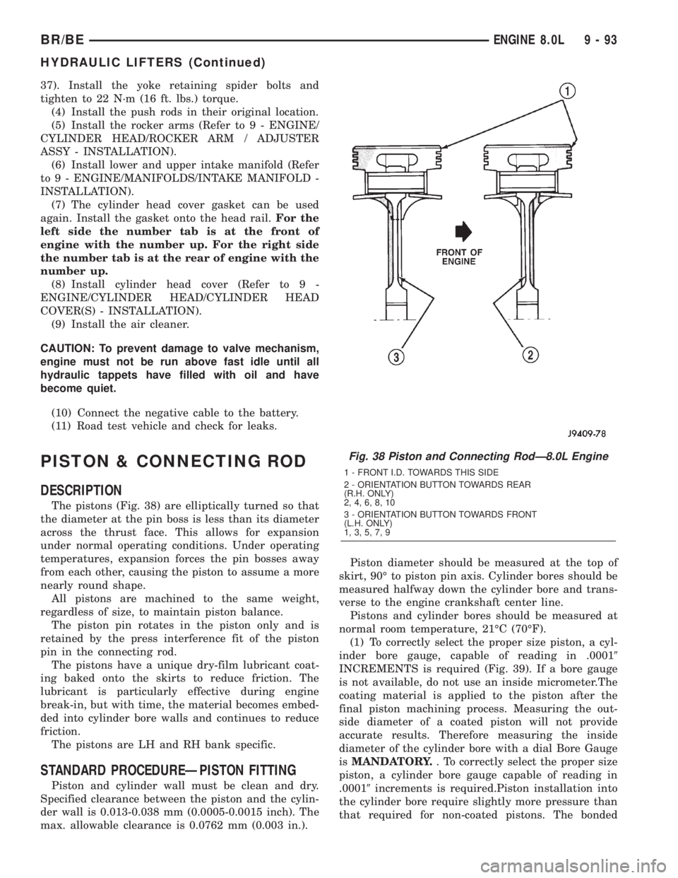
The pistons (Fig. 38) are elliptically turned so that
the diameter at the pin boss is less than its diameter
across the thrust face. This allows for expansion
under normal operating conditions. Under operating
temperatures, expansion forces the pin bosses away
from each other, causing the piston to assume a more
nearly round shape.
All pistons are machined to the same weight,
regardless of size, to maintain piston balance.
The piston pin rotates in the piston only and is
retained by the press interference fit of the piston
pin in the connecting rod.
The pistons have a unique dry-film lubricant coat-
ing baked onto the skirts to reduce friction. The
lubricant is particularly effective during engine
break-in, but with time, the material becomes embed-
ded into cylinder bore walls and continues to reduce
friction.
The pistons are LH and RH bank specific.
STANDARD PROCEDUREÐPISTON FITTING
Piston and cylinder wall must be clean and dry.
Specified clearance between the piston and the cylin-
der wall is 0.013-0.038 mm (0.0005-0.0015 inch). The
max. allowable clearance is 0.0762 mm (0.003 in.).Piston diameter should be measured at the top of
skirt, 90É to piston pin axis. Cylinder bores should be
measured halfway down the cylinder bore and trans-
verse to the engine crankshaft center line.
Pistons and cylinder bores should be measured at
normal room temperature, 21ÉC (70ÉF).
(1) To correctly select the proper size piston, a cyl-
inder bore gauge, capable of reading in .00019
INCREMENTS is required (Fig. 39). If a bore gauge
is not available, do not use an inside micrometer.The
coating material is applied to the piston after the
final piston machining process. Measuring the out-
side diameter of a coated piston will not provide
accurate results. Therefore measuring the inside
diameter of the cylinder bore with a dial Bore Gauge
isMANDATORY.. To correctly select the proper size
piston, a cylinder bore gauge capable of reading in
.00019increments is required.Piston installation into
the cylinder bore require slightly more pressure than
that required for non-coated pistons. The bonded
Fig. 38 Piston and Connecting RodÐ8.0L Engine
1 - FRONT I.D. TOWARDS THIS SIDE
2 - ORIENTATION BUTTON TOWARDS REAR
(R.H. ONLY)
2, 4, 6, 8, 10
3 - ORIENTATION BUTTON TOWARDS FRONT
(L.H. ONLY)
1, 3, 5, 7, 9
BR/BEENGINE 8.0L 9 - 93
HYDRAULIC LIFTERS (Continued)
Page 1173 of 2255
INSTALLATION
(1) With engine raised SLIGHTLY, position the
engine support bracket/cushion and heat shields to
the block. Install new bolts and tighten to 81 N´m (60
ft. lbs.) torque.
(2) Install the thru-bolt and 2 piece rubber engine
rubber restrictors onto the engine support bracket/
cushion.
(3) Lower engine with support/lifting fixture while
guiding the engine bracket/cushion and thru-bolt into
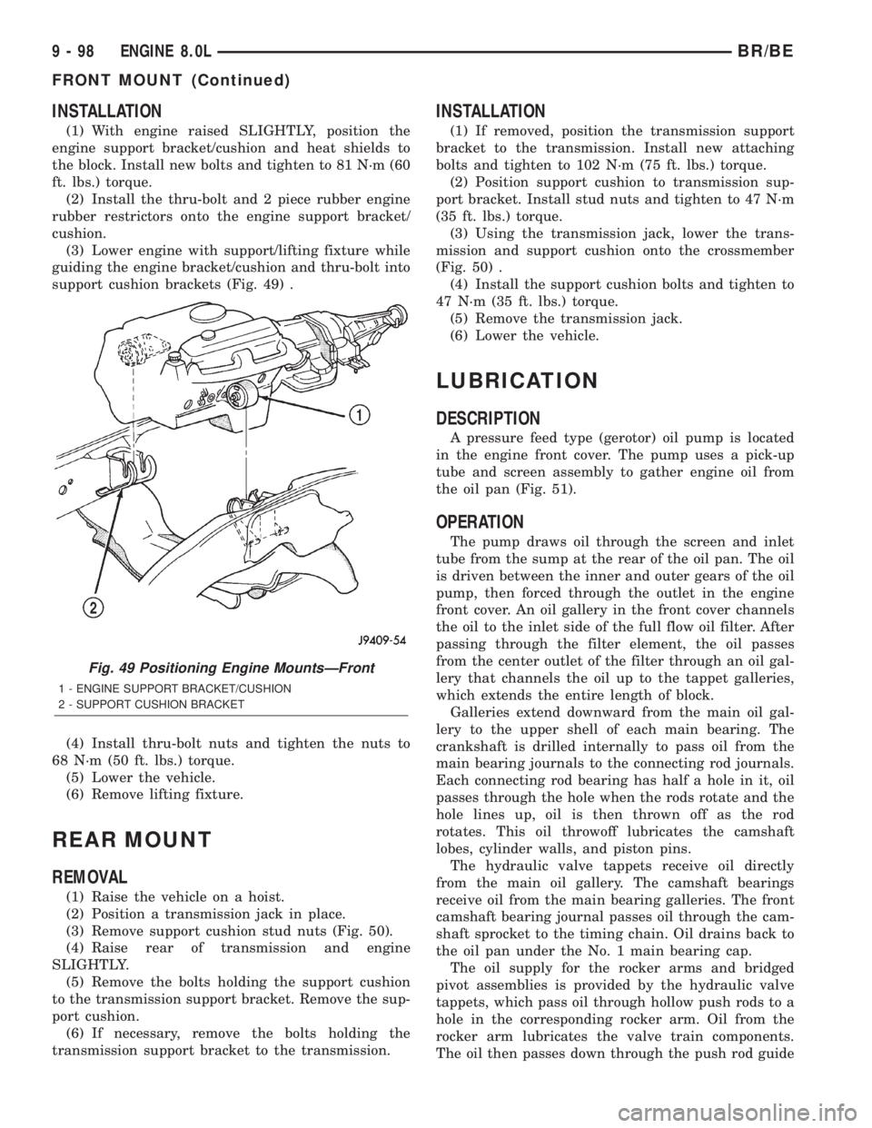
support cushion brackets (Fig. 49) .
(4) Install thru-bolt nuts and tighten the nuts to
68 N´m (50 ft. lbs.) torque.
(5) Lower the vehicle.
(6) Remove lifting fixture.
REAR MOUNT
REMOVAL
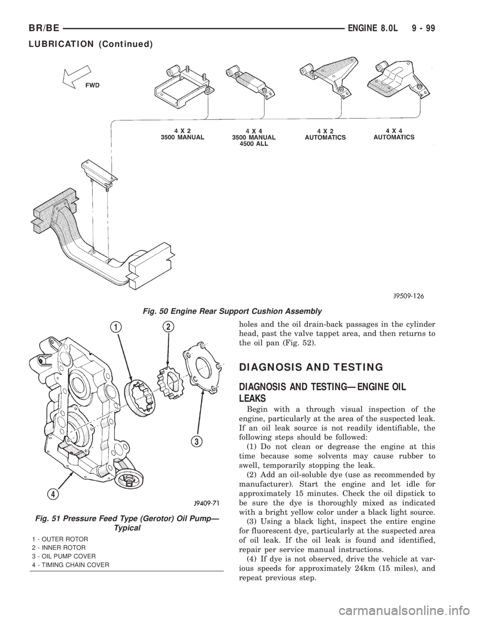
(1) Raise the vehicle on a hoist.
(2) Position a transmission jack in place.
(3) Remove support cushion stud nuts (Fig. 50).
(4) Raise rear of transmission and engine
SLIGHTLY.
(5) Remove the bolts holding the support cushion
to the transmission support bracket. Remove the sup-
port cushion.
(6) If necessary, remove the bolts holding the
transmission support bracket to the transmission.
INSTALLATION
(1) If removed, position the transmission support
bracket to the transmission. Install new attaching
bolts and tighten to 102 N´m (75 ft. lbs.) torque.
(2) Position support cushion to transmission sup-
port bracket. Install stud nuts and tighten to 47 N´m
(35 ft. lbs.) torque.
(3) Using the transmission jack, lower the trans-
mission and support cushion onto the crossmember
(Fig. 50) .
(4) Install the support cushion bolts and tighten to
47 N´m (35 ft. lbs.) torque.
(5) Remove the transmission jack.
(6) Lower the vehicle.
LUBRICATION
DESCRIPTION
A pressure feed type (gerotor) oil pump is located
in the engine front cover. The pump uses a pick-up
tube and screen assembly to gather engine oil from
the oil pan (Fig. 51).
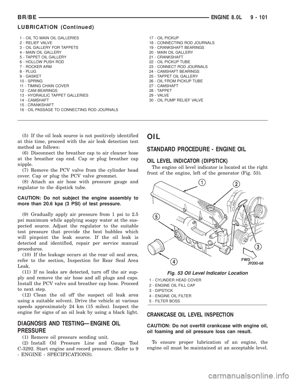
OPERATION
The pump draws oil through the screen and inlet
tube from the sump at the rear of the oil pan. The oil
is driven between the inner and outer gears of the oil
pump, then forced through the outlet in the engine
front cover. An oil gallery in the front cover channels
the oil to the inlet side of the full flow oil filter. After
passing through the filter element, the oil passes
from the center outlet of the filter through an oil gal-
lery that channels the oil up to the tappet galleries,
which extends the entire length of block.
Galleries extend downward from the main oil gal-
lery to the upper shell of each main bearing. The
crankshaft is drilled internally to pass oil from the
main bearing journals to the connecting rod journals.
Each connecting rod bearing has half a hole in it, oil
passes through the hole when the rods rotate and the
hole lines up, oil is then thrown off as the rod
rotates. This oil throwoff lubricates the camshaft
lobes, cylinder walls, and piston pins.
The hydraulic valve tappets receive oil directly
from the main oil gallery. The camshaft bearings
receive oil from the main bearing galleries. The front
camshaft bearing journal passes oil through the cam-
shaft sprocket to the timing chain. Oil drains back to
the oil pan under the No. 1 main bearing cap.
The oil supply for the rocker arms and bridged
pivot assemblies is provided by the hydraulic valve
tappets, which pass oil through hollow push rods to a
hole in the corresponding rocker arm. Oil from the
rocker arm lubricates the valve train components.
The oil then passes down through the push rod guide
Fig. 49 Positioning Engine MountsÐFront
1 - ENGINE SUPPORT BRACKET/CUSHION
2 - SUPPORT CUSHION BRACKET
9 - 98 ENGINE 8.0LBR/BE
FRONT MOUNT (Continued)
Page 1174 of 2255
holes and the oil drain-back passages in the cylinder
head, past the valve tappet area, and then returns to
the oil pan (Fig. 52).
DIAGNOSIS AND TESTING
DIAGNOSIS AND TESTINGÐENGINE OIL
LEAKS
Begin with a through visual inspection of the
engine, particularly at the area of the suspected leak.
If an oil leak source is not readily identifiable, the
following steps should be followed:
(1) Do not clean or degrease the engine at this
time because some solvents may cause rubber to
swell, temporarily stopping the leak.
(2) Add an oil-soluble dye (use as recommended by
manufacturer). Start the engine and let idle for
approximately 15 minutes. Check the oil dipstick to
be sure the dye is thoroughly mixed as indicated
with a bright yellow color under a black light source.
(3) Using a black light, inspect the entire engine
for fluorescent dye, particularly at the suspected area
of oil leak. If the oil leak is found and identified,
repair per service manual instructions.
(4) If dye is not observed, drive the vehicle at var-
ious speeds for approximately 24km (15 miles), and
repeat previous step.
Fig. 50 Engine Rear Support Cushion Assembly
Fig. 51 Pressure Feed Type (Gerotor) Oil PumpÐ
Typical
1 - OUTER ROTOR
2 - INNER ROTOR
3 - OIL PUMP COVER
4 - TIMING CHAIN COVER
BR/BEENGINE 8.0L 9 - 99
LUBRICATION (Continued)
Page 1176 of 2255
(5) If the oil leak source is not positively identified
at this time, proceed with the air leak detection test
method as follows:
(6) Disconnect the breather cap to air cleaner hose
at the breather cap end. Cap or plug breather cap
nipple.
(7) Remove the PCV valve from the cylinder head
cover. Cap or plug the PCV valve grommet.
(8) Attach an air hose with pressure gauge and
regulator to the dipstick tube.
CAUTION: Do not subject the engine assembly to
more than 20.6 kpa (3 PSI) of test pressure.
(9) Gradually apply air pressure from 1 psi to 2.5
psi maximum while applying soapy water at the sus-
pected source. Adjust the regulator to the suitable
test pressure that provide the best bubbles which
will pinpoint the leak source. If the oil leak is
detected and identified, repair per service manual
procedures.
(10) If the leakage occurs at the rear oil seal area,
refer to the section, Inspection for Rear Seal Area
Leak.
(11) If no leaks are detected, turn off the air sup-
ply and remove the air hose and all plugs and caps.
Install the PCV valve and breather cap hose. Proceed
to next step.
(12) Clean the oil off the suspect oil leak area
using a suitable solvent. Drive the vehicle at various
speeds approximately 24 km (15 miles). Inspect the
engine for signs of an oil leak by using a black light.
DIAGNOSIS AND TESTINGÐENGINE OIL
PRESSURE
(1) Remove oil pressure sending unit.
(2) Install Oil Pressure Line and Gauge Tool
C-3292. Start engine and record pressure. (Refer to 9
- ENGINE - SPECIFICATIONS).
OIL
STANDARD PROCEDURE - ENGINE OIL
OIL LEVEL INDICATOR (DIPSTICK)
The engine oil level indicator is located at the right
front of the engine, left of the generator (Fig. 53).
CRANKCASE OIL LEVEL INSPECTION
CAUTION: Do not overfill crankcase with engine oil,
oil foaming and oil pressure loss can result.
To ensure proper lubrication of an engine, the
engine oil must be maintained at an acceptable level.
1 - OIL TO MAIN OIL GALLERIES
2 - RELIEF VALVE
3 - OIL GALLERY FOR TAPPETS
4 - MAIN OIL GALLERY
5 - TAPPET OIL GALLERY
6 - HOLLOW PUSH ROD
7 - ROCKER ARM
8 - PLUG
9 - GASKET
10 - SPRING
11 - TIMING CHAIN COVER
12 - CAM BEARINGS
13 - HYDRAULIC TAPPET GALLERIES
14 - CAMSHAFT
15 - CRANKSHAFT
16 - OIL PASSAGE TO CONNECTING ROD JOURNALS17 - OIL PICKUP
18 - CONNECTING ROD JOURNALS
19 - CRANKSHAFT BEARINGS
20 - MAIN OIL GALLERY
21 - CRANKSHAFT
22 - OIL PICKUP TUBE
23 - CONNECT ROD JOURNALS
24 - CAMSHAFT BEARINGS
25 - TAPPET OIL GALLERY
26 - OIL FROM PICKUP TUBE
27 - CAMSHAFT
28 - TAPPET
29 - VALVE
30 - OIL PUMP RELIEF VALVE
Fig. 53 Oil Level Indicator Location
1 - CYLINDER HEAD COVER
2 - ENGINE OIL FILL CAP
3 - DIPSTICK
4 - ENGINE OIL FILTER
5 - FILTER BOSS
BR/BEENGINE 8.0L 9 - 101
LUBRICATION (Continued)
Page 1179 of 2255
OIL PUMP
REMOVAL
(1) Remove the timing chain cover (Refer to 9 -
ENGINE/VALVE TIMING/TIMING BELT / CHAIN
COVER(S) - REMOVAL).
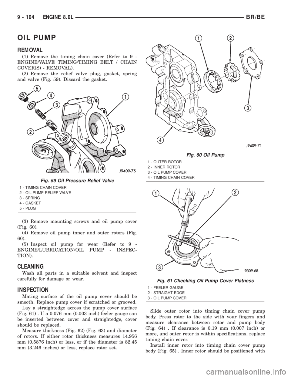
(2) Remove the relief valve plug, gasket, spring
and valve (Fig. 59). Discard the gasket.
(3) Remove mounting screws and oil pump cover
(Fig. 60).
(4) Remove oil pump inner and outer rotors (Fig.
60).
(5) Inspect oil pump for wear (Refer to 9 -
ENGINE/LUBRICATION/OIL PUMP - INSPEC-
TION).
CLEANING
Wash all parts in a suitable solvent and inspect
carefully for damage or wear.
INSPECTION
Mating surface of the oil pump cover should be
smooth. Replace pump cover if scratched or grooved.
Lay a straightedge across the pump cover surface
(Fig. 61) . If a 0.076 mm (0.003 inch) feeler gauge can
be inserted between cover and straightedge, cover
should be replaced.
Measure thickness (Fig. 62) (Fig. 63) and diameter
of rotors. If either rotor thickness measures 14.956
mm (0.5876 inch) or less, or if the diameter is 82.45
mm (3.246 inches) or less, replace rotor set.Slide outer rotor into timing chain cover pump
body. Press rotor to the side with your fingers and
measure clearance between rotor and pump body
(Fig. 64) . If clearance is 0.19 mm (0.007 inch) or
more, and outer rotor is within specifications, replace
timing chain cover.
Install inner rotor into timing chain cover pump
body (Fig. 65) . Inner rotor should be positioned with
Fig. 59 Oil Pressure Relief Valve
1 - TIMING CHAIN COVER
2 - OIL PUMP RELIEF VALVE
3 - SPRING
4 - GASKET
5 - PLUG
Fig. 60 Oil Pump
1 - OUTER ROTOR
2 - INNER ROTOR
3 - OIL PUMP COVER
4 - TIMING CHAIN COVER
Fig. 61 Checking Oil Pump Cover Flatness
1 - FEELER GAUGE
2 - STRAIGHT EDGE
3 - OIL PUMP COVER
9 - 104 ENGINE 8.0LBR/BE
Page 1180 of 2255
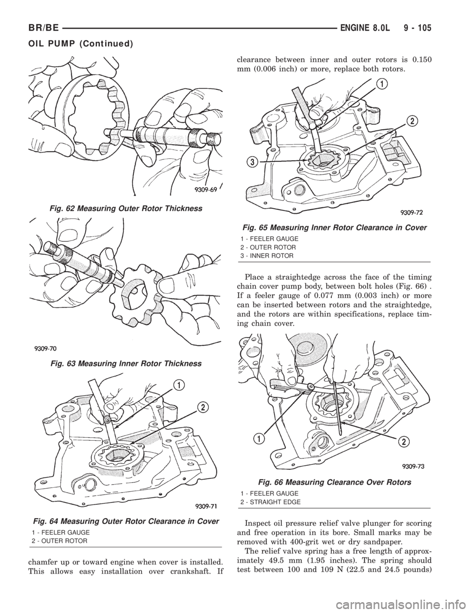
chamfer up or toward engine when cover is installed.
This allows easy installation over crankshaft. Ifclearance between inner and outer rotors is 0.150
mm (0.006 inch) or more, replace both rotors.
Place a straightedge across the face of the timing
chain cover pump body, between bolt holes (Fig. 66) .
If a feeler gauge of 0.077 mm (0.003 inch) or more
can be inserted between rotors and the straightedge,
and the rotors are within specifications, replace tim-
ing chain cover.
Inspect oil pressure relief valve plunger for scoring
and free operation in its bore. Small marks may be
removed with 400-grit wet or dry sandpaper.
The relief valve spring has a free length of approx-
imately 49.5 mm (1.95 inches). The spring should
test between 100 and 109 N (22.5 and 24.5 pounds)
Fig. 62 Measuring Outer Rotor Thickness
Fig. 63 Measuring Inner Rotor Thickness
Fig. 64 Measuring Outer Rotor Clearance in Cover
1 - FEELER GAUGE
2 - OUTER ROTOR
Fig. 65 Measuring Inner Rotor Clearance in Cover
1 - FEELER GAUGE
2 - OUTER ROTOR
3 - INNER ROTOR
Fig. 66 Measuring Clearance Over Rotors
1 - FEELER GAUGE
2 - STRAIGHT EDGE
BR/BEENGINE 8.0L 9 - 105
OIL PUMP (Continued)