2002 CHRYSLER VOYAGER compressor
[x] Cancel search: compressorPage 1401 of 2399
assembly, determined by the numbers stamped on
the crown of individual pistons. Engine cylinders are
numbered starting from gear train end of the engine.
Face arrow on top of piston toward front of
engine. Therefore, the numbers stamped on connect-
ing rod big end should face toward the injection
pump side of engine. To insert piston into cylinder
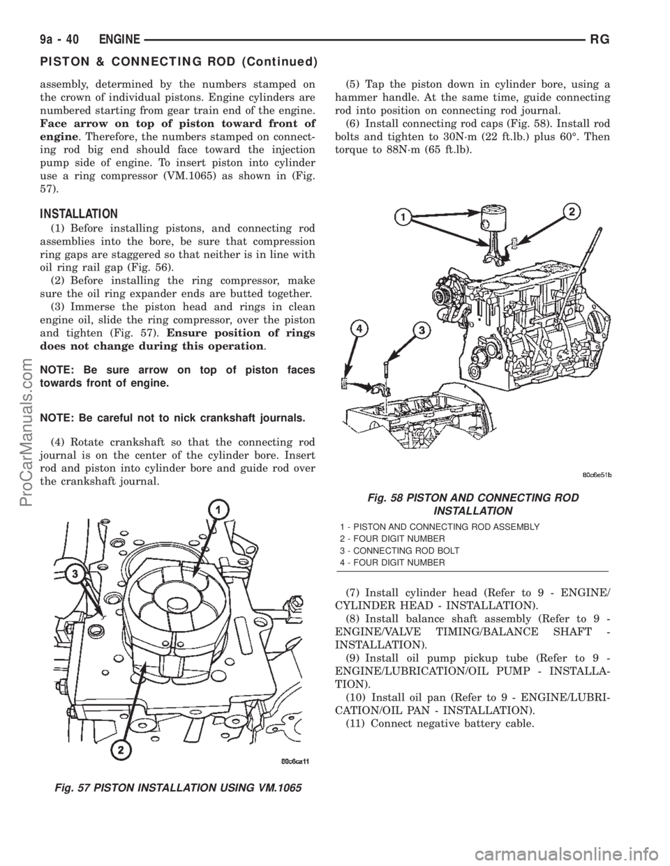
use a ring compressor (VM.1065) as shown in (Fig.
57).
INSTALLATION
(1) Before installing pistons, and connecting rod
assemblies into the bore, be sure that compression
ring gaps are staggered so that neither is in line with
oil ring rail gap (Fig. 56).
(2) Before installing the ring compressor, make
sure the oil ring expander ends are butted together.
(3) Immerse the piston head and rings in clean
engine oil, slide the ring compressor, over the piston
and tighten (Fig. 57).Ensure position of rings
does not change during this operation.
NOTE: Be sure arrow on top of piston faces
towards front of engine.
NOTE: Be careful not to nick crankshaft journals.
(4) Rotate crankshaft so that the connecting rod
journal is on the center of the cylinder bore. Insert
rod and piston into cylinder bore and guide rod over
the crankshaft journal.(5) Tap the piston down in cylinder bore, using a
hammer handle. At the same time, guide connecting
rod into position on connecting rod journal.
(6) Install connecting rod caps (Fig. 58). Install rod
bolts and tighten to 30N´m (22 ft.lb.) plus 60É. Then
torque to 88N´m (65 ft.lb).
(7) Install cylinder head (Refer to 9 - ENGINE/
CYLINDER HEAD - INSTALLATION).
(8) Install balance shaft assembly (Refer to 9 -
ENGINE/VALVE TIMING/BALANCE SHAFT -
INSTALLATION).
(9) Install oil pump pickup tube (Refer to 9 -
ENGINE/LUBRICATION/OIL PUMP - INSTALLA-
TION).
(10) Install oil pan (Refer to 9 - ENGINE/LUBRI-
CATION/OIL PAN - INSTALLATION).
(11) Connect negative battery cable.
Fig. 57 PISTON INSTALLATION USING VM.1065
Fig. 58 PISTON AND CONNECTING ROD
INSTALLATION
1 - PISTON AND CONNECTING ROD ASSEMBLY
2 - FOUR DIGIT NUMBER
3 - CONNECTING ROD BOLT
4 - FOUR DIGIT NUMBER
9a - 40 ENGINERG
PISTON & CONNECTING ROD (Continued)
ProCarManuals.com
Page 1435 of 2399
TURBOCHARGER SYSTEM
DESCRIPTION
CAUTION: The turbocharger is a performance part
and must not be tampered with. The wastegate
bracket is an integral part of the turbocharger. Tam-
pering with the wastegate components can reduce
durability by increasing cylinder pressure and ther-
mal loading due to incorrect inlet and exhaust man-
ifold pressure. Poor fuel economy and failure to
meet regulatory emissions laws may result. Increas-
ing the turbocharger boost WILL NOT increase
engine power.
The turbocharger is an exhaust-driven super-
charger which increases the pressure and density of
the air entering the engine. With the increase of air
entering the engine, more fuel can be injected into
the cylinders, which creates more power during com-
bustion.
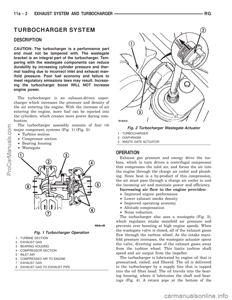
The turbocharger assembly consists of four (4)
major component systems (Fig. 1) (Fig. 2):
²Turbine section
²Compressor section
²Bearing housing
²Wastegate
OPERATION
Exhaust gas pressure and energy drive the tur-
bine, which in turn drives a centrifugal compressor
that compresses the inlet air, and forces the air into
the engine through the charge air cooler and plumb-
ing. Since heat is a by-product of this compression,
the air must pass through a charge air cooler to cool
the incoming air and maintain power and efficiency.
Increasing air flow to the engine provides:
²Improved engine performance
²Lower exhaust smoke density
²Improved operating economy
²Altitude compensation
²Noise reduction.
The turbocharger also uses a wastegate (Fig. 3),
which regulates intake manifold air pressure and
prevents over boosting at high engine speeds. When
the wastegate valve is closed, all of the exhaust gases
flow through the turbine wheel. As the intake mani-
fold pressure increases, the wastegate actuator opens
the valve, diverting some of the exhaust gases away
from the turbine wheel. This limits turbine shaft
speed and air output from the impeller.
The turbocharger is lubricated by engine oil that is
pressurized, cooled, and filtered. The oil is delivered
to the turbocharger by a supply line that is tapped
into the oil filter head. The oil travels into the bear-
ing housing, where it lubricates the shaft and bear-
ings (Fig. 4). A return pipe at the bottom of the
Fig. 1 Turbocharger Operation
1 - TURBINE SECTION
2 - EXHAUST GAS
3 - BEARING HOUSING
4 - COMPRESSOR SECTION
5 - INLET AIR
6 - COMPRESSED AIR TO ENGINE
7 - EXHAUST GAS
8 - EXHAUST GAS TO EXHAUST PIPE
Fig. 2 Turbocharger Wastegate Actuator
1 - TURBOCHARGER
2 - DIAPHRAGM
3 - WASTE GATE ACTUATOR
11a - 2 EXHAUST SYSTEM AND TURBOCHARGERRG
ProCarManuals.com
Page 1470 of 2399
The PCM compares the upstream and downstream
heated oxygen sensor inputs to measure catalytic con-
vertor efficiency. If the catalyst efficiency drops below
the minimum acceptable percentage, the PCM stores a
diagnostic trouble code in memory, after 2 trips.
During certain idle conditions, the PCM may enter
a variable idle speed strategy. During variable idle
speed strategy the PCM adjusts engine speed based
on the following inputs.
²A/C sense
²Battery voltage
²Battery temperature or Calculated Battery Tem-
perature
²Engine coolant temperature
²Engine run time
²Inlet/Intake air temperature
²Vehicle mileage
ACCELERATION MODE
This is a CLOSED LOOP mode. The PCM recog-
nizes an abrupt increase in Throttle Position sensor
output voltage or MAP sensor output voltage as a
demand for increased engine output and vehicle
acceleration. The PCM increases injector pulse width
in response to increased fuel demand.
²Wide Open Throttle-open loop
DECELERATION MODE
This is a CLOSED LOOP mode. During decelera-
tion the following inputs are received by the PCM:
²A/C sense
²Battery voltage
²Inlet/Intake air temperature
²Engine coolant temperature
²Crankshaft position (engine speed)
²Exhaust gas oxygen content (upstream heated
oxygen sensor)
²Knock sensor
²Manifold absolute pressure
²Throttle position sensor
²IAC motor (solenoid) control changes in response
to MAP sensor feedback
The PCM may receive a closed throttle input from
the Throttle Position Sensor (TPS) when it senses an
abrupt decrease in manifold pressure. This indicates a
hard deceleration (Open Loop). In response, the PCM
may momentarily turn off the injectors. This helps
improve fuel economy, emissions and engine braking.
WIDE-OPEN-THROTTLE MODE
This is an OPEN LOOP mode. During wide-open-
throttle operation, the following inputs are used by
the PCM:
²Inlet/Intake air temperature
²Engine coolant temperature
²Engine speed
²Knock sensor²Manifold absolute pressure
²Throttle position
When the PCM senses a wide-open-throttle condi-
tion through the Throttle Position Sensor (TPS) it de-
energizes the A/C compressor clutch relay. This
disables the air conditioning system and disables
EGR (if equipped).
The PCM adjusts injector pulse width to supply a
predetermined amount of additional fuel, based on
MAP and RPM.
IGNITION SWITCH OFF MODE
When the operator turns the ignition switch to the
OFF position, the following occurs:
²All outputs are turned off, unless 02 Heater
Monitor test is being run. Refer to the Emission sec-
tion for On-Board Diagnostics.
²No inputs are monitored except for the heated
oxygen sensors. The PCM monitors the heating ele-
ments in the oxygen sensors and then shuts down.
FUEL CORRECTION or ADAPTIVE MEMORIES
DESCRIPTION
In Open Loop, the PCM changes pulse width with-
out feedback from the O2 Sensors. Once the engine
warms up to approximately 30 to 35É F, the PCM
goes into closed loopShort Term Correctionand
utilizes feedback from the O2 Sensors. Closed loop
Long Term Adaptive Memoryis maintained above
170É to 190É F unless the PCM senses wide open
throttle. At that time the PCM returns to Open Loop
operation.
OPERATION
Short Term
The first fuel correction program that begins func-
tioning is the short term fuel correction. This system
corrects fuel delivery in direct proportion to the read-
ings from the Upstream O2 Sensor.
The PCM monitors the air/fuel ratio by using the
input voltage from the O2 Sensor. When the voltage
reaches its preset high or low limit, the PCM begins
to add or remove fuel until the sensor reaches its
switch point. The short term corrections then begin.
The PCM makes a series of quick changes in the
injector pulse-width until the O2 Sensor reaches its
opposite preset limit or switch point. The process
then repeats itself in the opposite direction.
Short term fuel correction will keep increasing or
decreasing injector pulse-width based upon the
upstream O2 Sensor input. The maximum range of
authority for short term memory is 25% (+/-) of base
pulse-width. Short term is violated and is lost when
ignition is turned OFF.
RSFUEL INJECTION14-19
FUEL INJECTION (Continued)
ProCarManuals.com
Page 1478 of 2399
FUEL PUMP RELAY
DESCRIPTION
The fuel pump relay is located in the PDC. The
inside top of the PDC cover has a label showing relay
and fuse location.
OPERATION
The fuel pump relay supplies battery voltage to the
fuel pump. A buss bar in the Power Distribution Cen-
ter (PDC) supplies voltage to the solenoid side and
contact side of the relay. The fuel pump relay power
circuit contains a fuse between the buss bar in the
PDC and the relay. The fuse is located in the PDC.
Refer to the Wiring Diagrams for circuit information.
The PCM controls the fuel pump relay by switch-
ing the ground path for the solenoid side of the relay
on and off. The PCM turns the ground path off when
the ignition switch is in the Off position. When the
ignition switch is in the On position, the PCM ener-
gizes the fuel pump. If the crankshaft position sensor
does not detect engine rotation, the PCM de-ener-
gizes the relay after approximately one second.
IDLE AIR CONTROL MOTOR
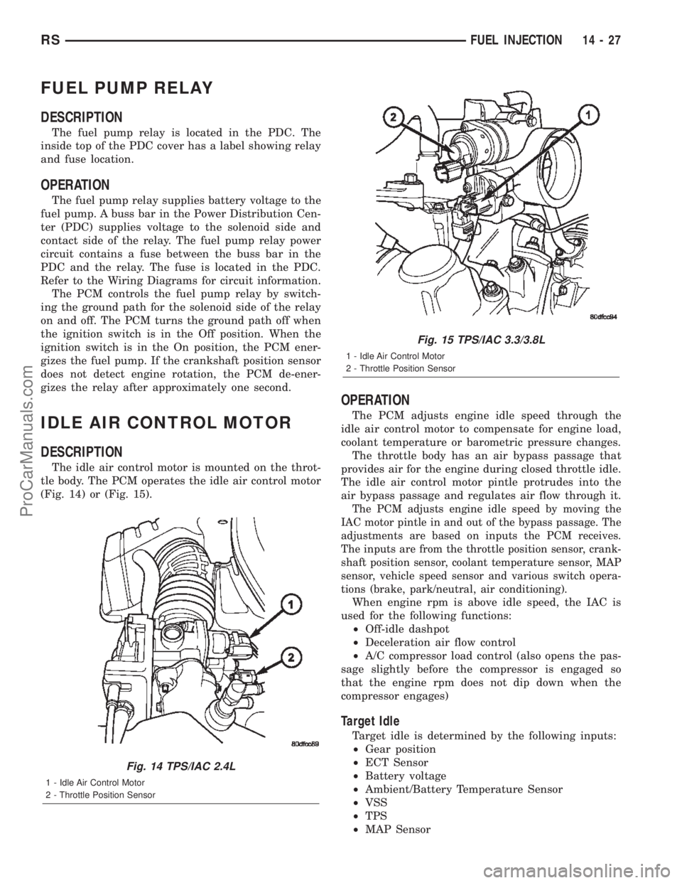
DESCRIPTION
The idle air control motor is mounted on the throt-
tle body. The PCM operates the idle air control motor
(Fig. 14) or (Fig. 15).
OPERATION
The PCM adjusts engine idle speed through the
idle air control motor to compensate for engine load,
coolant temperature or barometric pressure changes.
The throttle body has an air bypass passage that
provides air for the engine during closed throttle idle.
The idle air control motor pintle protrudes into the
air bypass passage and regulates air flow through it.
The PCM adjusts engine idle speed by moving the
IAC motor pintle in and out of the bypass passage. The
adjustments are based on inputs the PCM receives.
The inputs are from the throttle position sensor, crank-
shaft position sensor, coolant temperature sensor, MAP
sensor, vehicle speed sensor and various switch opera-
tions (brake, park/neutral, air conditioning).
When engine rpm is above idle speed, the IAC is
used for the following functions:
²Off-idle dashpot
²Deceleration air flow control
²A/C compressor load control (also opens the pas-
sage slightly before the compressor is engaged so
that the engine rpm does not dip down when the
compressor engages)
Target Idle
Target idle is determined by the following inputs:
²Gear position
²ECT Sensor
²Battery voltage
²Ambient/Battery Temperature Sensor
²VSS
²TPS
²MAP Sensor
Fig. 14 TPS/IAC 2.4L
1 - Idle Air Control Motor
2 - Throttle Position Sensor
Fig. 15 TPS/IAC 3.3/3.8L
1 - Idle Air Control Motor
2 - Throttle Position Sensor
RSFUEL INJECTION14-27
ProCarManuals.com
Page 1632 of 2399
SPECIAL TOOLS
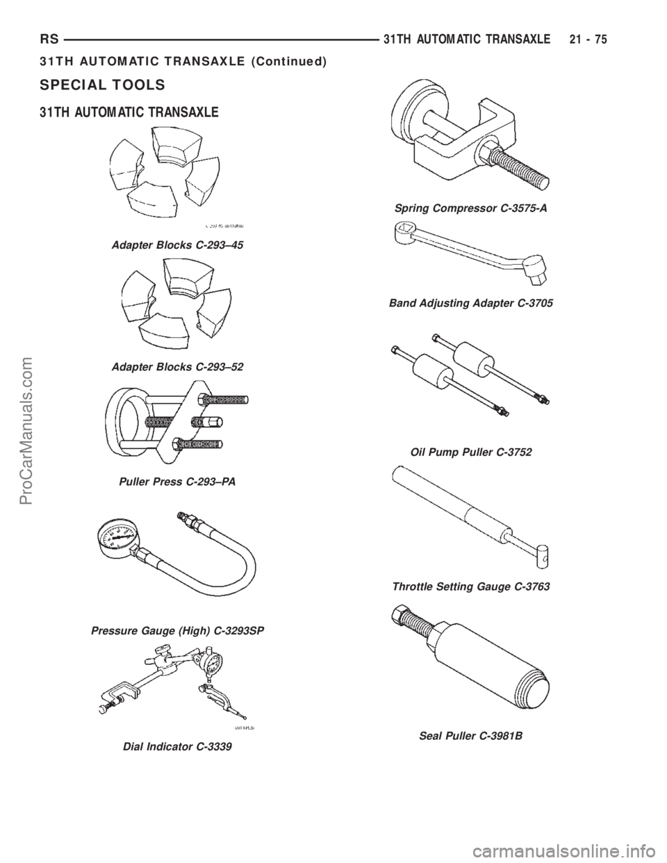
31TH AUTOMATIC TRANSAXLE
Adapter Blocks C-293±45
Adapter Blocks C-293±52
Puller Press C-293±PA
Pressure Gauge (High) C-3293SP
Dial Indicator C-3339
Spring Compressor C-3575-A
Band Adjusting Adapter C-3705
Oil Pump Puller C-3752
Throttle Setting Gauge C-3763
Seal Puller C-3981B
RS31TH AUTOMATIC TRANSAXLE21-75
31TH AUTOMATIC TRANSAXLE (Continued)
ProCarManuals.com
Page 1640 of 2399
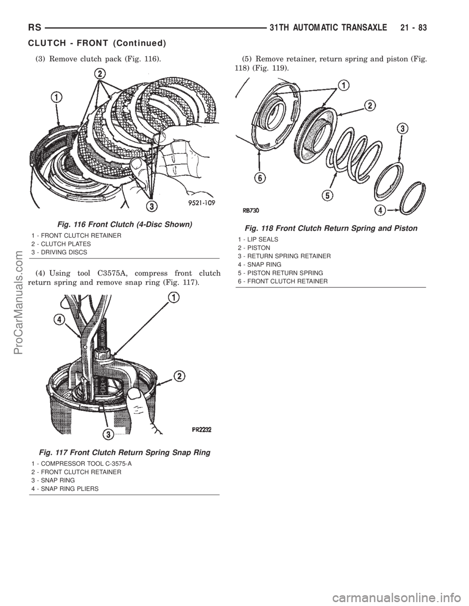
(3) Remove clutch pack (Fig. 116).
(4) Using tool C3575A, compress front clutch
return spring and remove snap ring (Fig. 117).(5) Remove retainer, return spring and piston (Fig.
118) (Fig. 119).
Fig. 116 Front Clutch (4-Disc Shown)
1 - FRONT CLUTCH RETAINER
2 - CLUTCH PLATES
3 - DRIVING DISCS
Fig. 117 Front Clutch Return Spring Snap Ring
1 - COMPRESSOR TOOL C-3575-A
2 - FRONT CLUTCH RETAINER
3 - SNAP RING
4 - SNAP RING PLIERS
Fig. 118 Front Clutch Return Spring and Piston
1 - LIP SEALS
2 - PISTON
3 - RETURN SPRING RETAINER
4 - SNAP RING
5 - PISTON RETURN SPRING
6 - FRONT CLUTCH RETAINER
RS31TH AUTOMATIC TRANSAXLE21-83
CLUTCH - FRONT (Continued)
ProCarManuals.com
Page 1642 of 2399
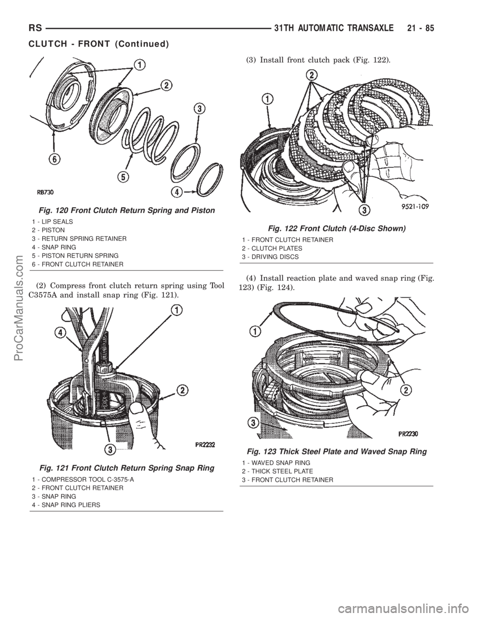
(2) Compress front clutch return spring using Tool
C3575A and install snap ring (Fig. 121).(3) Install front clutch pack (Fig. 122).
(4) Install reaction plate and waved snap ring (Fig.
123) (Fig. 124).
Fig. 120 Front Clutch Return Spring and Piston
1 - LIP SEALS
2 - PISTON
3 - RETURN SPRING RETAINER
4 - SNAP RING
5 - PISTON RETURN SPRING
6 - FRONT CLUTCH RETAINER
Fig. 121 Front Clutch Return Spring Snap Ring
1 - COMPRESSOR TOOL C-3575-A
2 - FRONT CLUTCH RETAINER
3 - SNAP RING
4 - SNAP RING PLIERS
Fig. 122 Front Clutch (4-Disc Shown)
1 - FRONT CLUTCH RETAINER
2 - CLUTCH PLATES
3 - DRIVING DISCS
Fig. 123 Thick Steel Plate and Waved Snap Ring
1 - WAVED SNAP RING
2 - THICK STEEL PLATE
3 - FRONT CLUTCH RETAINER
RS31TH AUTOMATIC TRANSAXLE21-85
CLUTCH - FRONT (Continued)
ProCarManuals.com
Page 1744 of 2399
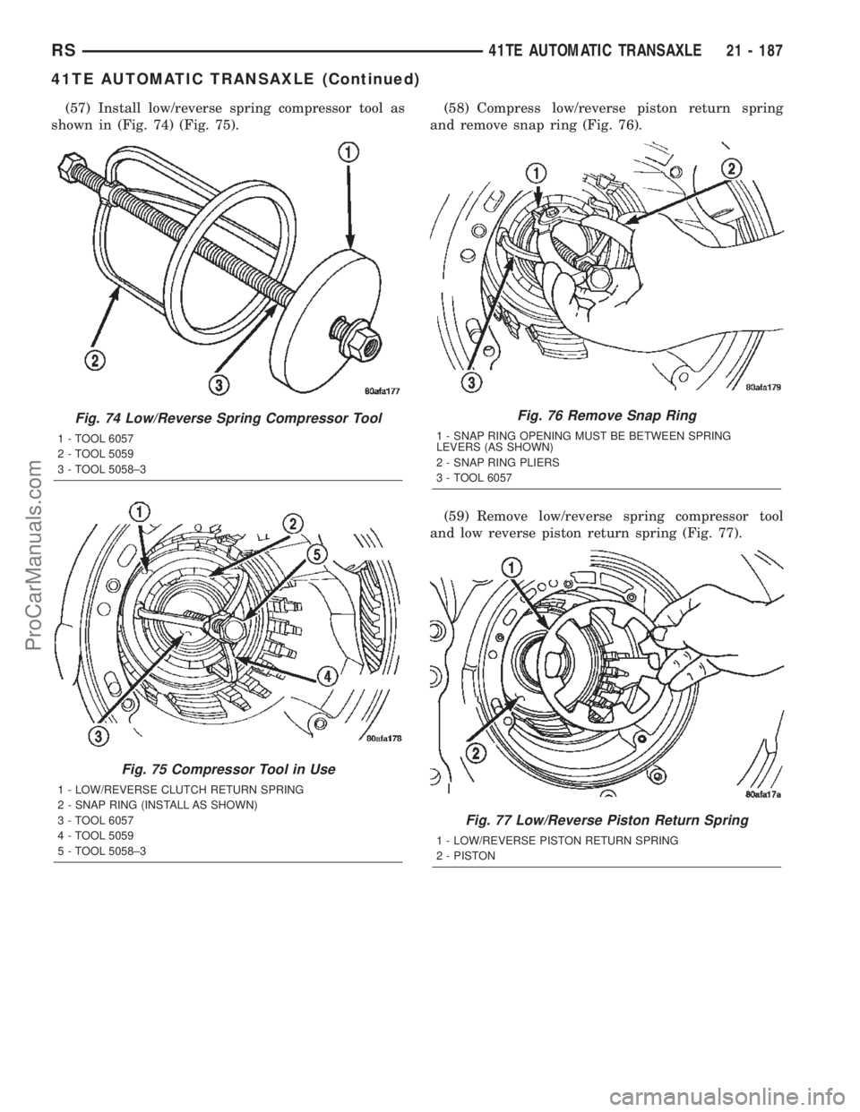
(57) Install low/reverse spring compressor tool as
shown in (Fig. 74) (Fig. 75).(58) Compress low/reverse piston return spring
and remove snap ring (Fig. 76).
(59) Remove low/reverse spring compressor tool
and low reverse piston return spring (Fig. 77).
Fig. 74 Low/Reverse Spring Compressor Tool
1 - TOOL 6057
2 - TOOL 5059
3 - TOOL 5058±3
Fig. 75 Compressor Tool in Use
1 - LOW/REVERSE CLUTCH RETURN SPRING
2 - SNAP RING (INSTALL AS SHOWN)
3 - TOOL 6057
4 - TOOL 5059
5 - TOOL 5058±3
Fig. 76 Remove Snap Ring
1 - SNAP RING OPENING MUST BE BETWEEN SPRING
LEVERS (AS SHOWN)
2 - SNAP RING PLIERS
3 - TOOL 6057
Fig. 77 Low/Reverse Piston Return Spring
1 - LOW/REVERSE PISTON RETURN SPRING
2 - PISTON
RS41TE AUTOMATIC TRANSAXLE21 - 187
41TE AUTOMATIC TRANSAXLE (Continued)
ProCarManuals.com