2002 CHRYSLER VOYAGER compressor
[x] Cancel search: compressorPage 1750 of 2399
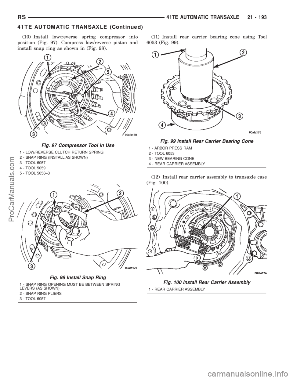
(10) Install low/reverse spring compressor into
position (Fig. 97). Compress low/reverse piston and
install snap ring as shown in (Fig. 98).(11) Install rear carrier bearing cone using Tool
6053 (Fig. 99).
(12) Install rear carrier assembly to transaxle case
(Fig. 100).
Fig. 97 Compressor Tool in Use
1 - LOW/REVERSE CLUTCH RETURN SPRING
2 - SNAP RING (INSTALL AS SHOWN)
3 - TOOL 6057
4 - TOOL 5059
5 - TOOL 5058±3
Fig. 98 Install Snap Ring
1 - SNAP RING OPENING MUST BE BETWEEN SPRING
LEVERS (AS SHOWN)
2 - SNAP RING PLIERS
3 - TOOL 6057
Fig. 99 Install Rear Carrier Bearing Cone
1 - ARBOR PRESS RAM
2 - TOOL 6053
3 - NEW BEARING CONE
4 - REAR CARRIER ASSEMBLY
Fig. 100 Install Rear Carrier Assembly
1 - REAR CARRIER ASSEMBLY
RS41TE AUTOMATIC TRANSAXLE21 - 193
41TE AUTOMATIC TRANSAXLE (Continued)
ProCarManuals.com
Page 1790 of 2399
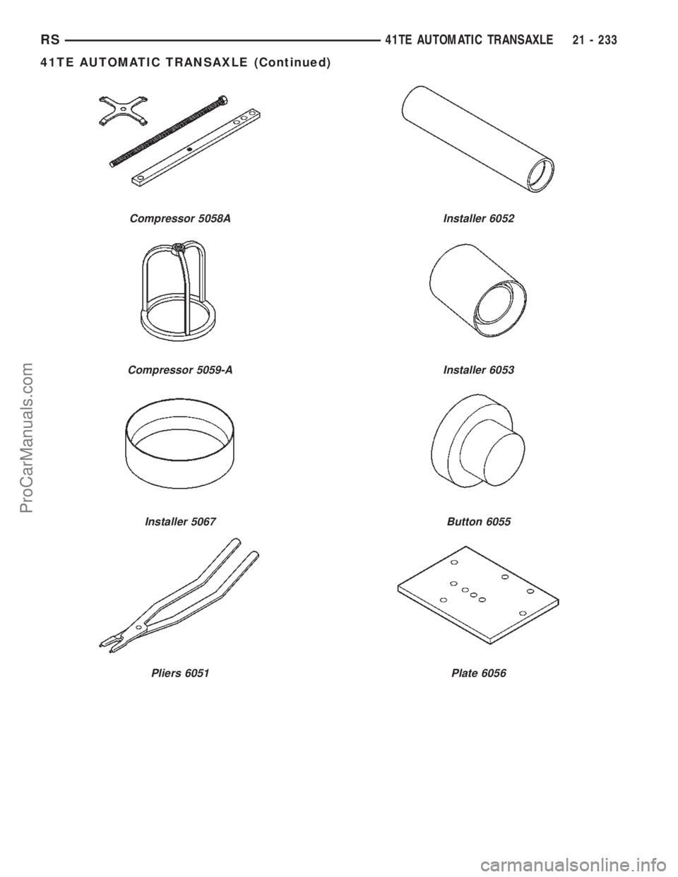
Compressor 5058A
Compressor 5059-A
Installer 5067
Pliers 6051
Installer 6052
Installer 6053
Button 6055
Plate 6056
RS41TE AUTOMATIC TRANSAXLE21 - 233
41TE AUTOMATIC TRANSAXLE (Continued)
ProCarManuals.com
Page 1822 of 2399
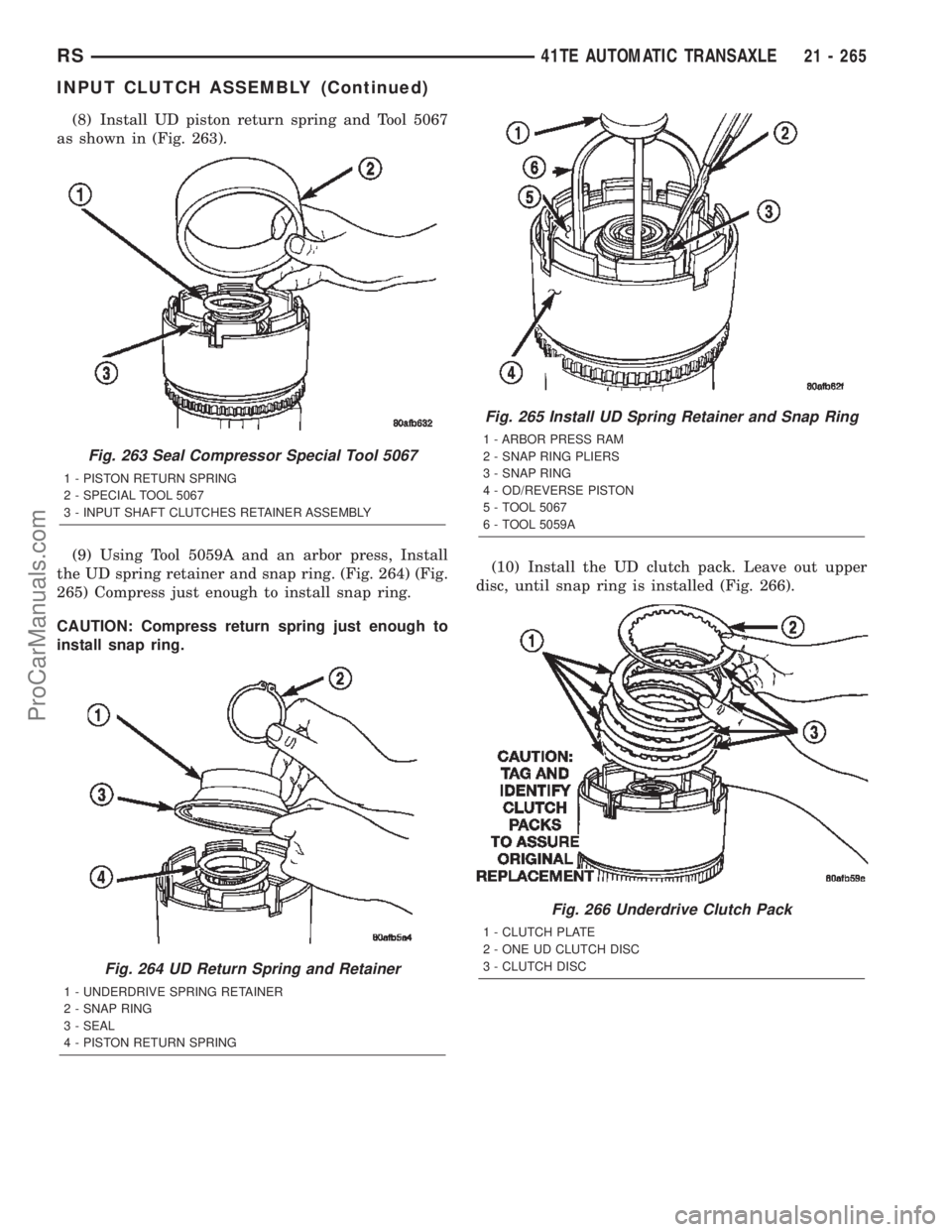
(8) Install UD piston return spring and Tool 5067
as shown in (Fig. 263).
(9) Using Tool 5059A and an arbor press, Install
the UD spring retainer and snap ring. (Fig. 264) (Fig.
265) Compress just enough to install snap ring.
CAUTION: Compress return spring just enough to
install snap ring.(10) Install the UD clutch pack. Leave out upper
disc, until snap ring is installed (Fig. 266).
Fig. 263 Seal Compressor Special Tool 5067
1 - PISTON RETURN SPRING
2 - SPECIAL TOOL 5067
3 - INPUT SHAFT CLUTCHES RETAINER ASSEMBLY
Fig. 264 UD Return Spring and Retainer
1 - UNDERDRIVE SPRING RETAINER
2 - SNAP RING
3 - SEAL
4 - PISTON RETURN SPRING
Fig. 265 Install UD Spring Retainer and Snap Ring
1 - ARBOR PRESS RAM
2 - SNAP RING PLIERS
3 - SNAP RING
4 - OD/REVERSE PISTON
5 - TOOL 5067
6 - TOOL 5059A
Fig. 266 Underdrive Clutch Pack
1 - CLUTCH PLATE
2 - ONE UD CLUTCH DISC
3 - CLUTCH DISC
RS41TE AUTOMATIC TRANSAXLE21 - 265
INPUT CLUTCH ASSEMBLY (Continued)
ProCarManuals.com
Page 2246 of 2399
pressed, the set temp value will become 55 but the
display will show LO. If the set temp is 85 and the
up button is pressed, the set temp value will become
90 but the display will show HIGH. Temperatures
can be displayed in either metric or Fahrenheit,
which is controlled from the overhead console.
²A rocker switch that selects a cool-down rate.
LO-AUTO or HI-AUTO are displayed when the sys-
tem is in automatic operation.
²A defroster button which turns on the defroster
independently during full automatic control. A
defroster symbol illuminates in the display when the
button is pressed.
²Air recirculation button. A Recirculation symbol
appears in the display when the button is pressed, or
when the system exceeds 80 percent circulated air
under automatic control due to high air conditioning
demand.
²Rear window defogger on/off switch. A graphic
symbol shows when the defroster is on.
²An air conditioning button that allows the com-
pressor to be turned off. A Snowflake symbol is illu-
minated when air conditioning is on, whether under
manual or automatic control.
²Rotary knob for front fan speed selection can
override the automatic controls. LEDs surrounding
the knob show the current setting.
²Rotary knob for control of the Rear system.
²A rotary knob for mode control can override the
automatic controls. LEDs surrounding the knob show
the current setting.
²Computer logic remembers the settings of the
controls when the ignition is turned off and retains
those settings after a restart. If the system is off
when the ignition is turned off it will be off when the
engine is restarted, etc.
²Computer logic provides variable air recircula-
tion under high temperature and humidity condi-
tions. Because recirculation is generally accompanied
by increased fan noise, the proportion of recirculated
to outside air gradually approaches full recirculation
over a broad temperature range.
²A graphic symbol of the windshield that illumi-
nates when the windshield wiper deicer is active.
REAR CONTROL PANEL
A rear control panel centrally mounted on the
headliner includes a vacuum-flourescent digital dis-
play, a rocker control for temperature and rotary con-
trols for adjustment of mode and fan speed control of
the rear unit by intermediate seat passengers.
OPERATION
OPERATION - DUAL ZONE
²The mode control knob enables continously vari-
able proportioning of air flow between modes but has
detents adjacent to each icon.
²The blower control provides five separate speeds.
²When the fan is off, the HVAC computer closes
the recirculation door to prevent outside air from
entering the passenger compartment.
²Interior air may be recirculated to speed up
heating or cooling in all modes except defrost and
mix by pressing the Recirculate button on the control
panel.
²To reduce humidity for rapid defogging the A/C
compressor runs automatically in modes from ªmix'
to full defrost when outside temperatures are above
freezing.
²Air conditioning is available in any mode by
pressing the snowflake, A/C on/off, button.
OPERATION - MANUAL THREE ZONE
FRONT CONTROL PANEL
²Primary control of the rear compartment unit is
on the instrument panel. This control allows the
driver to set the rear compartment fan speed, to turn
the rear unit off, or to give control to the intermedi-
ate seat occupants by switching to the REAR posi-
tion. When the rear unit is controlled from the
instrument panel, rear air temperature is based on
the driver-side temperature control position, and the
mode (floor or overhead air) is based on the front
control's mode position.
²The mode control knob enables continously vari-
able proportioning of air flow between modes but has
detents adjacent to each icon.
²The blower control provides five separate speeds
and Off. When the fan is off, the HVAC computer
closes the recirculation door to prevent outside air
from entering the passenger compartment.
²Interior air may be recirculated to speed up
heating or cooling in all modes exccept defrost and
mix by pressing the Recirculate button on the control
panel.
²To reduce humidity for rapid defogging the A/C
compressor runs automatically in modes from ªmix'
to full defrost when outside temperatures are above
freezing.
²Air conditioning is available in any mode by
pressing the snowflake, A/C on/off, button.
RSHEATING & AIR CONDITIONING24-3
HEATING & AIR CONDITIONING (Continued)
ProCarManuals.com
Page 2248 of 2399
control rear set temp button is pressed simulta-
neously with the rear control head, then the front
control head press events shall have priority, i.e. if
the front user presses Rear Set Temp down and the
rear user presses Set Temp up, then the rear set
temp will decrease.
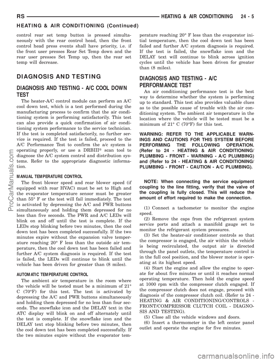
DIAGNOSIS AND TESTING
DIAGNOSIS AND TESTING - A/C COOL DOWN
TEST
The heater-A/C control module can perform an A/C
cool down test, which is a test performed during the
manufacturing process to confirm that the air condi-
tioning system is performing satisfactorily. This test
can also provide a quick confirmation of air condi-
tioning system performance to the service technician.
If the test is completed satisfactorily, no further ser-
vice is required. If the test is failed, proceed to the
A/C Performance Test to confirm the a/c system is
operating properly, or use a DRBIIItscan tool to
diagnose the A/C system control and distribution sys-
tems. Refer to the appropriate diagnostic informa-
tion.
MANUAL TEMPERATURE CONTROL
The front blower speed and rear blower speed (if
equipped with rear HVAC) must be set to High and
the evaporator temperature sensor must be greater
than 55É F or the test will fail immediately. The test
is activated by depressing the A/C and PWR buttons
simultaneously and holding them depressed for no
less than five seconds. The PWR and A/C LEDs will
blink on and off until the test is complete. If the
LEDs stop blinking before two minutes, then the cool
down test has been completed successfully. If the two
minutes expire without the expansion valve temper-
ature reaching 20É F less than the outside air tem-
perature, then the cool down test has been failed and
further A/C system diagnosis is required. If the test
is failed, the LEDs will continue to blink until the
vehicle has been driven for greater than (8 miles).
AUTOMATIC TEMPERATURE CONTROL
The ambient air temperature in the room where
the vehicle will be tested must be a minimum of 21É
C (70ÉF) for this test. The test is activated by
depressing the A/C and PWR buttons simultaneously
and holding them depressed for no less than four sec-
onds. The snowflake icon and the DELAY text in the
ATC display will blink on and off alternately until
the test is complete. If the snowflake icon and the
DELAY text stop blinking before two minutes, then
the cool down test has been completed successfully. If
the two minutes expire without the evaporator tem-perature reaching 20É F less than the evaporator ini-
tial temperature, then the cool down test has been
failed and further A/C system diagnosis is required.
If the test is failed, the snowflake icon and the
DELAY text will continue to blink across ignition
cycles until the vehicle has been driven for greater
than (8 miles).
DIAGNOSIS AND TESTING - A/C
PERFORMANCE TEST
An air conditioning performance test is the best
way to determine whether the system is performing
up to standard. This test also provides valuable clues
as to the possible cause of trouble with the air con-
ditioning system. The ambient air temperature in the
location where the vehicle will be tested must be a
minimum of 21É C (70ÉF) for this test.
WARNING: REFER TO THE APPLICABLE WARN-
INGS AND CAUTIONS FOR THIS SYSTEM BEFORE
PERFORMING THE FOLLOWING OPERATION.
(Refer to 24 - HEATING & AIR CONDITIONING/
PLUMBING - FRONT - WARNING - A/C PLUMBING)
and (Refer to 24 - HEATING & AIR CONDITIONING/
PLUMBING - FRONT - CAUTION - A/C PLUMBING).
NOTE: When connecting the service equipment
coupling to the line fitting, verify that the valve of
the coupling is fully closed. This will reduce the
amount of effort required to make the connection.
(1) Connect a tachometer to monitor the engine
speed.
(2) Remove the caps from the refrigerant system
service ports and attach a manifold gauge set to
monitor the refrigerant system pressures.
(3) Set the heater-air conditioner controls so that
the compressor is engaged, the air within the vehicle
is being recirculated, the output air is directed
through the panel outlets, the temperature control is
in the full cool position, and the blower motor is oper-
ating at its highest speed.
(4) Start the engine and allow the engine to oper-
ate for about five minutes or until it reaches normal
operating temperature. Then hold the engine speed
at 1000 rpm with the compressor clutch engaged. If
the compressor clutch does not engage, proceed with
diagnosis of the compressor clutch coil. (Refer to 24 -
HEATING & AIR CONDITIONING/CONTROLS -
FRONT/COMPRESSOR CLUTCH COIL - DIAGNO-
SIS AND TESTING).
(5) Close all the vehicle windows and doors.
(6) Insert a thermometer in the left center panel
outlet and operate the engine for five minutes.
RSHEATING & AIR CONDITIONING24-5
HEATING & AIR CONDITIONING (Continued)
ProCarManuals.com
Page 2249 of 2399
(7) With the compressor clutch engaged, record the
left center panel outlet discharge air temperature,
the discharge pressure (high side service port), and
the suction pressure (low side service port). The com-
pressor clutch may cycle, depending upon the ambi-
ent temperature and humidity. If the clutch cycles,
use the readings obtained before the clutch disen-
gaged.
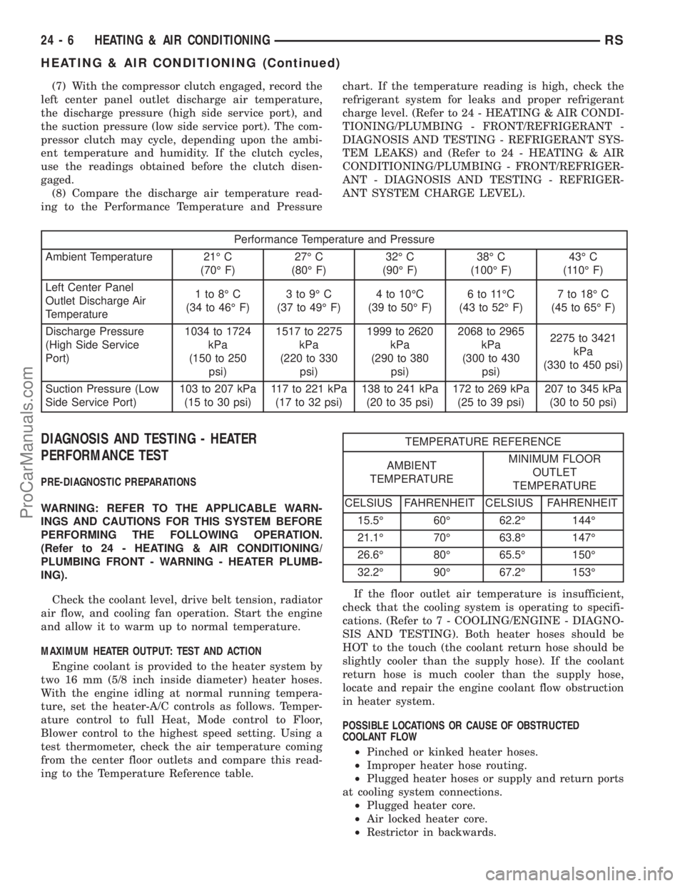
(8) Compare the discharge air temperature read-
ing to the Performance Temperature and Pressurechart. If the temperature reading is high, check the
refrigerant system for leaks and proper refrigerant
charge level. (Refer to 24 - HEATING & AIR CONDI-
TIONING/PLUMBING - FRONT/REFRIGERANT -
DIAGNOSIS AND TESTING - REFRIGERANT SYS-
TEM LEAKS) and (Refer to 24 - HEATING & AIR
CONDITIONING/PLUMBING - FRONT/REFRIGER-
ANT - DIAGNOSIS AND TESTING - REFRIGER-
ANT SYSTEM CHARGE LEVEL).
Performance Temperature and Pressure
Ambient Temperature 21É C
(70É F)27É C
(80É F)32É C
(90É F)38É C
(100É F)43É C
(110É F)
Left Center Panel
Outlet Discharge Air
Temperature1to8ÉC
(34 to 46É F)3to9ÉC
(37 to 49É F)4 to 10ÉC
(39 to 50É F)6to11ÉC
(43 to 52É F)7 to 18É C
(45 to 65É F)
Discharge Pressure
(High Side Service
Port)1034 to 1724
kPa
(150 to 250
psi)1517 to 2275
kPa
(220 to 330
psi)1999 to 2620
kPa
(290 to 380
psi)2068 to 2965
kPa
(300 to 430
psi)2275 to 3421
kPa
(330 to 450 psi)
Suction Pressure (Low
Side Service Port)103 to 207 kPa
(15 to 30 psi)117 to 221 kPa
(17 to 32 psi)138 to 241 kPa
(20 to 35 psi)172 to 269 kPa
(25 to 39 psi)207 to 345 kPa
(30 to 50 psi)
DIAGNOSIS AND TESTING - HEATER
PERFORMANCE TEST
PRE-DIAGNOSTIC PREPARATIONS
WARNING: REFER TO THE APPLICABLE WARN-
INGS AND CAUTIONS FOR THIS SYSTEM BEFORE
PERFORMING THE FOLLOWING OPERATION.
(Refer to 24 - HEATING & AIR CONDITIONING/
PLUMBING FRONT - WARNING - HEATER PLUMB-
ING).
Check the coolant level, drive belt tension, radiator
air flow, and cooling fan operation. Start the engine
and allow it to warm up to normal temperature.
MAXIMUM HEATER OUTPUT: TEST AND ACTION
Engine coolant is provided to the heater system by
two 16 mm (5/8 inch inside diameter) heater hoses.
With the engine idling at normal running tempera-
ture, set the heater-A/C controls as follows. Temper-
ature control to full Heat, Mode control to Floor,
Blower control to the highest speed setting. Using a
test thermometer, check the air temperature coming
from the center floor outlets and compare this read-
ing to the Temperature Reference table.
TEMPERATURE REFERENCE
AMBIENT
TEMPERATUREMINIMUM FLOOR
OUTLET
TEMPERATURE
CELSIUS FAHRENHEIT CELSIUS FAHRENHEIT
15.5É 60É 62.2É 144É
21.1É 70É 63.8É 147É
26.6É 80É 65.5É 150É
32.2É 90É 67.2É 153É
If the floor outlet air temperature is insufficient,
check that the cooling system is operating to specifi-
cations. (Refer to 7 - COOLING/ENGINE - DIAGNO-
SIS AND TESTING). Both heater hoses should be
HOT to the touch (the coolant return hose should be
slightly cooler than the supply hose). If the coolant
return hose is much cooler than the supply hose,
locate and repair the engine coolant flow obstruction
in heater system.
POSSIBLE LOCATIONS OR CAUSE OF OBSTRUCTED
COOLANT FLOW
²Pinched or kinked heater hoses.
²Improper heater hose routing.
²Plugged heater hoses or supply and return ports
at cooling system connections.
²Plugged heater core.
²Air locked heater core.
²Restrictor in backwards.
24 - 6 HEATING & AIR CONDITIONINGRS
HEATING & AIR CONDITIONING (Continued)
ProCarManuals.com
Page 2250 of 2399
If coolant flow is verified and the heater floor out-
let temperature is insufficient, a mechanical problem
may exist.
POSSIBLE LOCATION OR CAUSE OF INSUFFICIENT HEAT
²Obstructed cowl air intake.
²Obstructed heater system outlets.
²Blend-air door not functioning properly.TEMPERATURE CONTROL
If heater floor outlet temperature cannot be
adjusted with the heater-A/C control temperature
control lever, one of the following could require ser-
vice:
²Blend-air door binding.
²Faulty blend-air door motor.
²Improper engine coolant temperature.
²Faulty heater-A/C control.
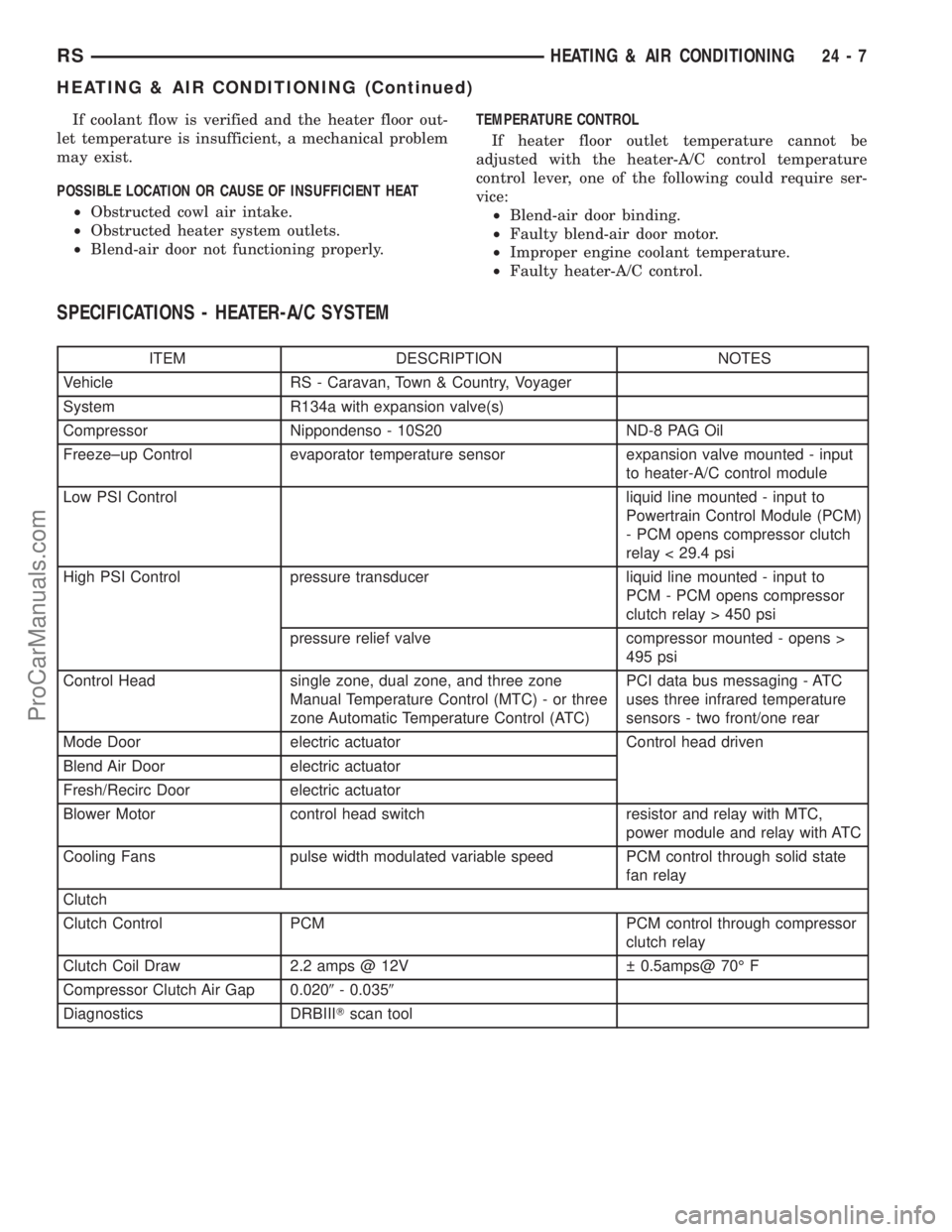
SPECIFICATIONS - HEATER-A/C SYSTEM
ITEM DESCRIPTION NOTES
Vehicle RS - Caravan, Town & Country, Voyager
System R134a with expansion valve(s)
Compressor Nippondenso - 10S20 ND-8 PAG Oil
Freeze±up Control evaporator temperature sensor expansion valve mounted - input
to heater-A/C control module
Low PSI Control liquid line mounted - input to
Powertrain Control Module (PCM)
- PCM opens compressor clutch
relay < 29.4 psi
High PSI Control pressure transducer liquid line mounted - input to
PCM - PCM opens compressor
clutch relay > 450 psi
pressure relief valve compressor mounted - opens >
495 psi
Control Head single zone, dual zone, and three zone
Manual Temperature Control (MTC) - or three
zone Automatic Temperature Control (ATC)PCI data bus messaging - ATC
uses three infrared temperature
sensors - two front/one rear
Mode Door electric actuator Control head driven
Blend Air Door electric actuator
Fresh/Recirc Door electric actuator
Blower Motor control head switch resistor and relay with MTC,
power module and relay with ATC
Cooling Fans pulse width modulated variable speed PCM control through solid state
fan relay
Clutch
Clutch Control PCM PCM control through compressor
clutch relay
Clutch Coil Draw 2.2 amps @ 12V 0.5amps@ 70É F
Compressor Clutch Air Gap 0.0209- 0.0359
Diagnostics DRBIIITscan tool
RSHEATING & AIR CONDITIONING24-7
HEATING & AIR CONDITIONING (Continued)
ProCarManuals.com
Page 2251 of 2399
CONTROLS - FRONT
TABLE OF CONTENTS
page page
A/C HEATER CONTROL
STANDARD PROCEDURE - HEATER-A/C
CONTROL CALIBRATION................8
REMOVAL.............................9
INSTALLATION..........................9
A/C PRESSURE TRANSDUCER
DESCRIPTION - A/C PRESSURE
TRANSDUCER.......................10
OPERATION...........................10
DIAGNOSIS AND TESTING - A/C PRESSURE
TRANSDUCER.......................10
REMOVAL.............................11
INSTALLATION.........................11
BLEND DOOR ACTUATOR
DESCRIPTION.........................11
OPERATION...........................11
REMOVAL.............................12
INSTALLATION.........................12
BLOWER MOTOR RELAY
DESCRIPTION.........................13
OPERATION...........................13
DIAGNOSIS AND TESTING - BLOWER
MOTOR RELAY.......................14
REMOVAL.............................14
INSTALLATION.........................14
BLOWER MOTOR RESISTOR
DESCRIPTION.........................15
OPERATION...........................15
DIAGNOSIS AND TESTING - BLOWER
MOTOR RESISTOR....................15
REMOVAL.............................16
INSTALLATION.........................16
COMPRESSOR CLUTCH
DESCRIPTION.........................16
OPERATION...........................17
STANDARD PROCEDURE
STANDARD PROCEDURE - COMPRESSOR
CLUTCH AIR GAP.....................17STANDARD PROCEDURE - COMPRESSOR
CLUTCH BREAK-IN....................17
REMOVAL.............................17
INSPECTION - COMPRESSOR CLUTCH/COIL . 18
INSTALLATION.........................19
COMPRESSOR CLUTCH COIL
DIAGNOSIS AND TESTING - COMPRESSOR
CLUTCH COIL........................20
COMPRESSOR CLUTCH RELAY
DESCRIPTION.........................21
OPERATION...........................21
DIAGNOSIS AND TESTING - COMPRESSOR
CLUTCH RELAY......................22
REMOVAL.............................22
INSTALLATION.........................22
EVAPORATOR TEMPERATURE SENSOR
DESCRIPTION.........................22
OPERATION...........................23
REMOVAL.............................23
INSTALLATION.........................23
INFRARED TEMPERATURE SENSOR
DESCRIPTION.........................24
OPERATION...........................24
MODE DOOR ACTUATOR
DESCRIPTION.........................24
OPERATION...........................25
REMOVAL.............................25
INSTALLATION.........................25
POWER MODULE
DESCRIPTION.........................26
OPERATION...........................26
REMOVAL.............................26
INSTALLATION.........................27
RECIRCULATION DOOR ACTUATOR
DESCRIPTION.........................27
OPERATION...........................27
REMOVAL.............................28
INSTALLATION.........................28
A/C HEATER CONTROL
STANDARD PROCEDURE - HEATER-A/C
CONTROL CALIBRATION
The heater-A/C control module must be recali-
brated each time an actuator motor or the control
module is replaced. If the vehicle is so equipped, the
calibration procedure also includes rear HVAC posi-
tions for each actuator motor.(1) Turn the ignition switch to the On position.
(2) Simultaneously depress and hold the Power
and Recirculation buttons on the heater-A/C control
for at least five seconds. The manual heater-A/C con-
trol power Light Emitting Diode (LED) and Recircu-
lation LED, or the Automatic Temperature Control
(ATC) heater-A/C control Delay and Recirculation
graphics will begin to flash when the calibration pro-
cedure has begun.
24 - 8 CONTROLS - FRONTRS
ProCarManuals.com