2002 CHRYSLER VOYAGER oil pressure sensor
[x] Cancel search: oil pressure sensorPage 1385 of 2399
CYLINDER HEAD COVER(S)
DESCRIPTION
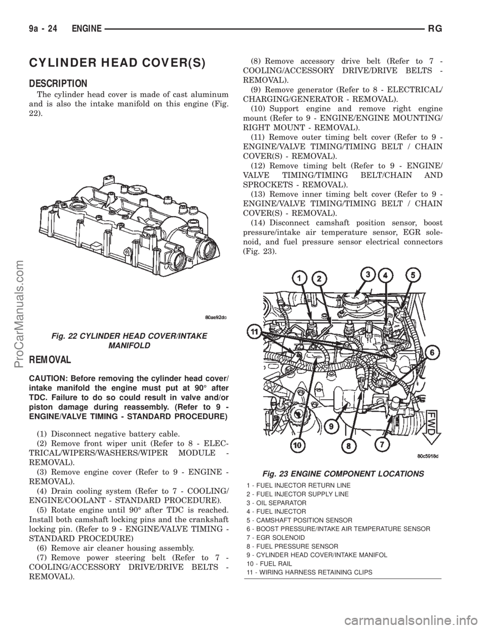
The cylinder head cover is made of cast aluminum
and is also the intake manifold on this engine (Fig.
22).
REMOVAL
CAUTION: Before removing the cylinder head cover/
intake manifold the engine must put at 90É after
TDC. Failure to do so could result in valve and/or
piston damage during reassembly. (Refer to 9 -
ENGINE/VALVE TIMING - STANDARD PROCEDURE)
(1) Disconnect negative battery cable.
(2) Remove front wiper unit (Refer to 8 - ELEC-
TRICAL/WIPERS/WASHERS/WIPER MODULE -
REMOVAL).
(3) Remove engine cover (Refer to 9 - ENGINE -
REMOVAL).
(4) Drain cooling system (Refer to 7 - COOLING/
ENGINE/COOLANT - STANDARD PROCEDURE).
(5) Rotate engine until 90É after TDC is reached.
Install both camshaft locking pins and the crankshaft
locking pin. (Refer to 9 - ENGINE/VALVE TIMING -
STANDARD PROCEDURE)
(6) Remove air cleaner housing assembly.
(7) Remove power steering belt (Refer to 7 -
COOLING/ACCESSORY DRIVE/DRIVE BELTS -
REMOVAL).(8) Remove accessory drive belt (Refer to 7 -
COOLING/ACCESSORY DRIVE/DRIVE BELTS -
REMOVAL).
(9) Remove generator (Refer to 8 - ELECTRICAL/
CHARGING/GENERATOR - REMOVAL).
(10) Support engine and remove right engine
mount (Refer to 9 - ENGINE/ENGINE MOUNTING/
RIGHT MOUNT - REMOVAL).
(11) Remove outer timing belt cover (Refer to 9 -
ENGINE/VALVE TIMING/TIMING BELT / CHAIN
COVER(S) - REMOVAL).
(12) Remove timing belt (Refer to 9 - ENGINE/
VALVE TIMING/TIMING BELT/CHAIN AND
SPROCKETS - REMOVAL).
(13) Remove inner timing belt cover (Refer to 9 -
ENGINE/VALVE TIMING/TIMING BELT / CHAIN
COVER(S) - REMOVAL).
(14) Disconnect camshaft position sensor, boost
pressure/intake air temperature sensor, EGR sole-
noid, and fuel pressure sensor electrical connectors
(Fig. 23).
Fig. 22 CYLINDER HEAD COVER/INTAKE
MANIFOLD
Fig. 23 ENGINE COMPONENT LOCATIONS
1 - FUEL INJECTOR RETURN LINE
2 - FUEL INJECTOR SUPPLY LINE
3 - OIL SEPARATOR
4 - FUEL INJECTOR
5 - CAMSHAFT POSITION SENSOR
6 - BOOST PRESSURE/INTAKE AIR TEMPERATURE SENSOR
7 - EGR SOLENOID
8 - FUEL PRESSURE SENSOR
9 - CYLINDER HEAD COVER/INTAKE MANIFOL
10 - FUEL RAIL
11 - WIRING HARNESS RETAINING CLIPS
9a - 24 ENGINERG
ProCarManuals.com
Page 1387 of 2399
NOTE: Be sure to lubricate cylinder head cover/in-
take manifold retaining bolts with engine oil before
assembly. If new bolts are being installed, DO NOT
lubricate before assembly.
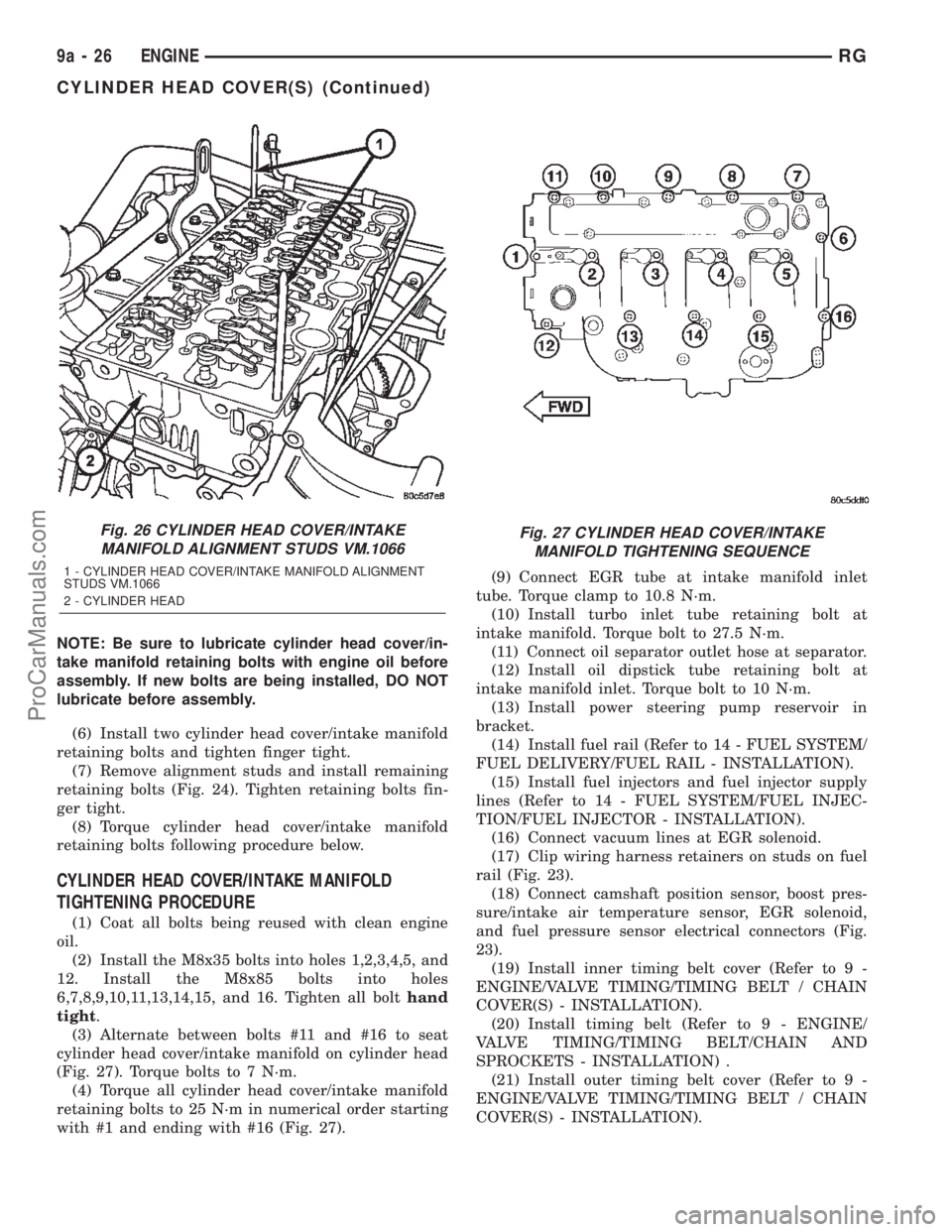
(6) Install two cylinder head cover/intake manifold
retaining bolts and tighten finger tight.
(7) Remove alignment studs and install remaining
retaining bolts (Fig. 24). Tighten retaining bolts fin-
ger tight.
(8) Torque cylinder head cover/intake manifold
retaining bolts following procedure below.
CYLINDER HEAD COVER/INTAKE MANIFOLD
TIGHTENING PROCEDURE
(1) Coat all bolts being reused with clean engine
oil.
(2) Install the M8x35 bolts into holes 1,2,3,4,5, and
12. Install the M8x85 bolts into holes
6,7,8,9,10,11,13,14,15, and 16. Tighten all bolthand
tight.
(3) Alternate between bolts #11 and #16 to seat
cylinder head cover/intake manifold on cylinder head
(Fig. 27). Torque bolts to 7 N´m.
(4) Torque all cylinder head cover/intake manifold
retaining bolts to 25 N´m in numerical order starting
with #1 and ending with #16 (Fig. 27).(9) Connect EGR tube at intake manifold inlet
tube. Torque clamp to 10.8 N´m.
(10) Install turbo inlet tube retaining bolt at
intake manifold. Torque bolt to 27.5 N´m.
(11) Connect oil separator outlet hose at separator.
(12) Install oil dipstick tube retaining bolt at
intake manifold inlet. Torque bolt to 10 N´m.
(13) Install power steering pump reservoir in
bracket.
(14) Install fuel rail (Refer to 14 - FUEL SYSTEM/
FUEL DELIVERY/FUEL RAIL - INSTALLATION).
(15) Install fuel injectors and fuel injector supply
lines (Refer to 14 - FUEL SYSTEM/FUEL INJEC-
TION/FUEL INJECTOR - INSTALLATION).
(16) Connect vacuum lines at EGR solenoid.
(17) Clip wiring harness retainers on studs on fuel
rail (Fig. 23).
(18) Connect camshaft position sensor, boost pres-
sure/intake air temperature sensor, EGR solenoid,
and fuel pressure sensor electrical connectors (Fig.
23).
(19) Install inner timing belt cover (Refer to 9 -
ENGINE/VALVE TIMING/TIMING BELT / CHAIN
COVER(S) - INSTALLATION).
(20) Install timing belt (Refer to 9 - ENGINE/
VALVE TIMING/TIMING BELT/CHAIN AND
SPROCKETS - INSTALLATION) .
(21) Install outer timing belt cover (Refer to 9 -
ENGINE/VALVE TIMING/TIMING BELT / CHAIN
COVER(S) - INSTALLATION).
Fig. 26 CYLINDER HEAD COVER/INTAKE
MANIFOLD ALIGNMENT STUDS VM.1066
1 - CYLINDER HEAD COVER/INTAKE MANIFOLD ALIGNMENT
STUDS VM.1066
2 - CYLINDER HEAD
Fig. 27 CYLINDER HEAD COVER/INTAKE
MANIFOLD TIGHTENING SEQUENCE
9a - 26 ENGINERG
CYLINDER HEAD COVER(S) (Continued)
ProCarManuals.com
Page 1407 of 2399
CRANKSHAFT OIL SEAL -
REAR
REMOVAL
This must be done with either the engine or trans-
mission removed from vehicle.
(1) Remove flywheel assembly.
(2) Pry out old crankshaft oil seal.
INSTALLATION
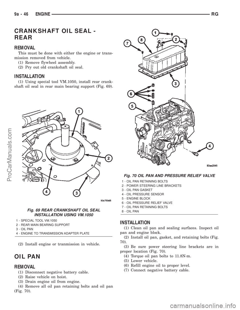
(1) Using special tool VM.1050, install rear crank-
shaft oil seal in rear main bearing support (Fig. 69).
(2) Install engine or tranmission in vehicle.
OIL PAN
REMOVAL
(1) Disconnect negative battery cable.
(2) Raise vehicle on hoist.
(3) Drain engine oil from engine.
(4) Remove all oil pan retaining bolts and oil pan
(Fig. 70).
INSTALLATION
(1) Clean oil pan and sealing surfaces. Inspect oil
pan and engine block.
(2) Install oil pan, gasket, and retaining bolts (Fig.
70).
(3) Be sure power steering line brackets are in
proper location (Fig. 70).
(4) Torque oil pan bolts to 11.8N´m.
(5) Lower vehicle.
(6) Refill engine oil to proper level.
(7) Connect negative battery cable.
Fig. 69 REAR CRANKSHAFT OIL SEAL
INSTALLATION USING VM.1050
1 - SPECIAL TOOL VM.1050
2 - REAR MAIN BEARING SUPPORT
3 - OIL PAN
4 - ENGINE TO TRANSMISSION ADAPTER PLATE
Fig. 70 OIL PAN AND PRESSURE RELIEF VALVE
1 - OIL PAN RETAINING BOLTS
2 - POWER STEERING LINE BRACKETS
3 - OIL PAN GASKET
4 - OIL PRESSURE SENSOR
5 - ENGINE BLOCK
6 - OIL PRESSURE RELIEF VALVE
7 - OIL PAN RETAINING BOLTS
8 - OIL PAN
9a - 46 ENGINERG
ProCarManuals.com
Page 1409 of 2399
(3) Install oil pump retaining bolts (Fig. 71).
Torque bolts to 10.8N´m.
(4) Install crankshaft sprocket (Fig. 71). Torque
bolts to 10.8N´m.
(5) Install front engine cover (Refer to 9 -
ENGINE/ENGINE BLOCK/ENGINE COVER -
INSTALLATION).
(6) Install timing belt inner cover (Refer to 9 -
ENGINE/VALVE TIMING/TIMING BELT / CHAIN
COVER(S) - INSTALLATION).
(7) Install timing belt (Refer to 9 - ENGINE/
VALVE TIMING/TIMING BELT/CHAIN AND
SPROCKETS - INSTALLATION) .
(8) Install timing belt outer cover (Refer to 9 -
ENGINE/VALVE TIMING/TIMING BELT / CHAIN
COVER(S) - INSTALLATION).
(9) Install accessory drive belt (Refer to 7 - COOL-
ING/ACCESSORY DRIVE/DRIVE BELTS - INSTAL-
LATION).
(10) Install power steering belt (Refer to 7 -
COOLING/ACCESSORY DRIVE/DRIVE BELTS -
INSTALLATION).
(11) Connect negative battery cable.
INSTALLATION
(1) Lubricate o-ring on oil pump pickup tube with
engine oil.
(2) Install pickup tube in engine block and install
retaining bolt (Fig. 72). Torque bolt to 32.4N´m.
(3) Install oil pan (Refer to 9 - ENGINE/LUBRI-
CATION/OIL PAN - INSTALLATION).
(4) Refill engine oil to proper level.
(5) Connect negative battery cable.
OIL PRESSURE SENSOR/
SWITCH
DESCRIPTION
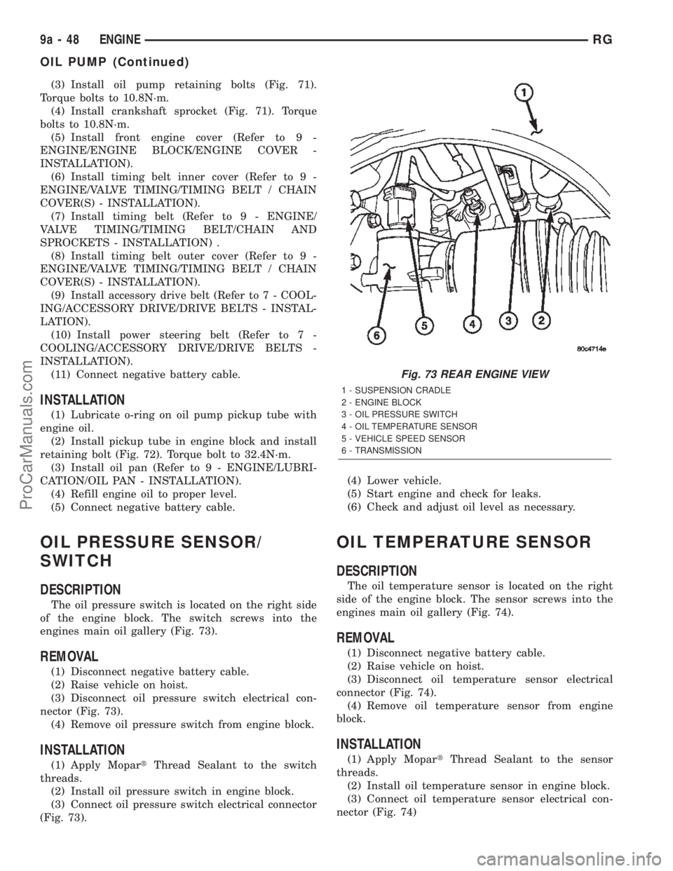
The oil pressure switch is located on the right side
of the engine block. The switch screws into the
engines main oil gallery (Fig. 73).
REMOVAL
(1) Disconnect negative battery cable.
(2) Raise vehicle on hoist.
(3) Disconnect oil pressure switch electrical con-
nector (Fig. 73).
(4) Remove oil pressure switch from engine block.
INSTALLATION
(1) Apply MopartThread Sealant to the switch
threads.
(2) Install oil pressure switch in engine block.
(3) Connect oil pressure switch electrical connector
(Fig. 73).(4) Lower vehicle.
(5) Start engine and check for leaks.
(6) Check and adjust oil level as necessary.
OIL TEMPERATURE SENSOR
DESCRIPTION
The oil temperature sensor is located on the right
side of the engine block. The sensor screws into the
engines main oil gallery (Fig. 74).
REMOVAL
(1) Disconnect negative battery cable.
(2) Raise vehicle on hoist.
(3) Disconnect oil temperature sensor electrical
connector (Fig. 74).
(4) Remove oil temperature sensor from engine
block.
INSTALLATION
(1) Apply MopartThread Sealant to the sensor
threads.
(2) Install oil temperature sensor in engine block.
(3) Connect oil temperature sensor electrical con-
nector (Fig. 74)
Fig. 73 REAR ENGINE VIEW
1 - SUSPENSION CRADLE
2 - ENGINE BLOCK
3 - OIL PRESSURE SWITCH
4 - OIL TEMPERATURE SENSOR
5 - VEHICLE SPEED SENSOR
6 - TRANSMISSION
9a - 48 ENGINERG
OIL PUMP (Continued)
ProCarManuals.com
Page 1410 of 2399
(4) Lower vehicle.
(5) Start engine and check for leaks.
(6) Check and adjust oil level as necessary.
OIL PRESSURE RELIEF VALVE
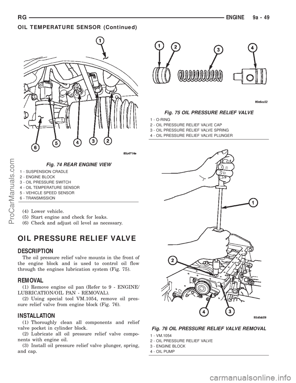
DESCRIPTION
The oil pressure relief valve mounts in the front of
the engine block and is used to control oil flow
through the engines lubrication system (Fig. 75).
REMOVAL
(1) Remove engine oil pan (Refer to 9 - ENGINE/
LUBRICATION/OIL PAN - REMOVAL).
(2) Using special tool VM.1054, remove oil pres-
sure relief valve from engine block (Fig. 76).
INSTALLATION
(1) Thoroughly clean all components and relief
valve pocket in cylinder block.
(2) Lubricate all oil pressure relief valve compo-
nents with engine oil.
(3) Install oil pressure relief valve plunger, spring,
and cap.
Fig. 74 REAR ENGINE VIEW
1 - SUSPENSION CRADLE
2 - ENGINE BLOCK
3 - OIL PRESSURE SWITCH
4 - OIL TEMPERATURE SENSOR
5 - VEHICLE SPEED SENSOR
6 - TRANSMISSION
Fig. 75 OIL PRESSURE RELIEF VALVE
1 - O-RING
2 - OIL PRESSURE RELIEF VALVE CAP
3 - OIL PRESSURE RELIEF VALVE SPRING
4 - OIL PRESSURE RELIEF VALVE PLUNGER
Fig. 76 OIL PRESSURE RELIEF VALVE REMOVAL
1 - VM.1054
2 - OIL PRESSURE RELIEF VALVE
3 - ENGINE BLOCK
4 - OIL PUMP
RGENGINE9a-49
OIL TEMPERATURE SENSOR (Continued)
ProCarManuals.com
Page 1449 of 2399
REMOVAL
The front cradle crossmember must be installed in
the design location to achieve proper front end sus-
pension alignment. If the cradle crossmember is
removed without applying reference marks on the
frame rails, align the cradle crossmember according
to the dimensions provided in this group.
NOTE: If the caged nuts in the frame rails become
damaged and cannot be reused, a replacement nut
can be obtained through MoparT.
REMOVAL
(1) Disconnect battery negative cable.
(2) Remove steering column lower cover from
instrument panel (Refer to 23 - BODY/INSTRU-
MENT PANEL/STEERING COLUMN OPENING
COVER - REMOVAL).
(3) Remove steering column cover backing plate
(Refer to 23 - BODY/INSTRUMENT PANEL/STEER-
ING COLUMN COVER BACKING PLATE - REMOV-
AL).
(4) Position steering so front wheels are straight
ahead.
CAUTION: Do not rotate steering wheel after disen-
gaging lower coupling from steering gear, damage
to air bag clock spring can result.
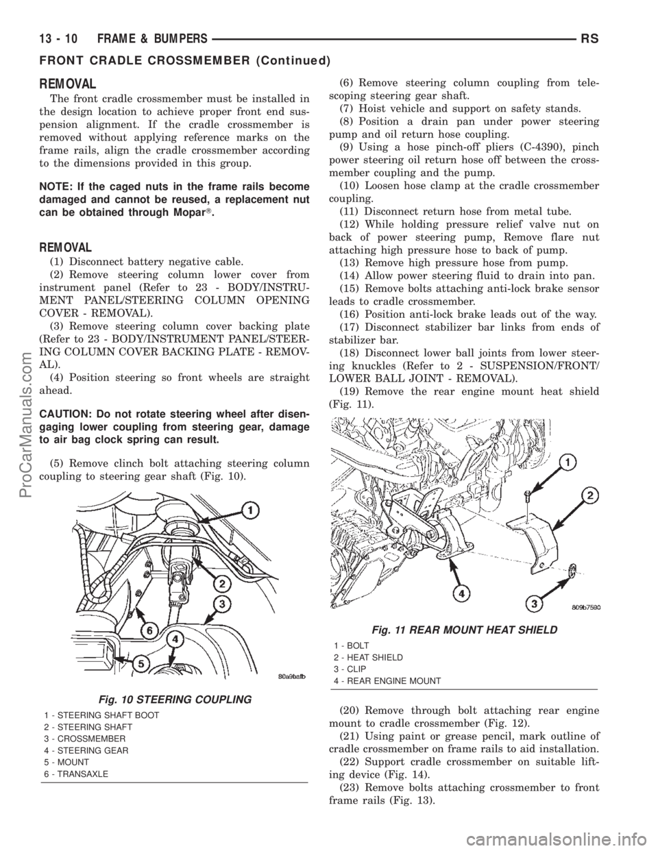
(5) Remove clinch bolt attaching steering column
coupling to steering gear shaft (Fig. 10).(6) Remove steering column coupling from tele-
scoping steering gear shaft.
(7) Hoist vehicle and support on safety stands.
(8) Position a drain pan under power steering
pump and oil return hose coupling.
(9) Using a hose pinch-off pliers (C-4390), pinch
power steering oil return hose off between the cross-
member coupling and the pump.
(10) Loosen hose clamp at the cradle crossmember
coupling.
(11) Disconnect return hose from metal tube.
(12) While holding pressure relief valve nut on
back of power steering pump, Remove flare nut
attaching high pressure hose to back of pump.
(13) Remove high pressure hose from pump.
(14) Allow power steering fluid to drain into pan.
(15) Remove bolts attaching anti-lock brake sensor
leads to cradle crossmember.
(16) Position anti-lock brake leads out of the way.
(17) Disconnect stabilizer bar links from ends of
stabilizer bar.
(18) Disconnect lower ball joints from lower steer-
ing knuckles (Refer to 2 - SUSPENSION/FRONT/
LOWER BALL JOINT - REMOVAL).
(19) Remove the rear engine mount heat shield
(Fig. 11).
(20) Remove through bolt attaching rear engine
mount to cradle crossmember (Fig. 12).
(21) Using paint or grease pencil, mark outline of
cradle crossmember on frame rails to aid installation.
(22) Support cradle crossmember on suitable lift-
ing device (Fig. 14).
(23) Remove bolts attaching crossmember to front
frame rails (Fig. 13).
Fig. 10 STEERING COUPLING
1 - STEERING SHAFT BOOT
2 - STEERING SHAFT
3 - CROSSMEMBER
4 - STEERING GEAR
5 - MOUNT
6 - TRANSAXLE
Fig. 11 REAR MOUNT HEAT SHIELD
1 - BOLT
2 - HEAT SHIELD
3 - CLIP
4 - REAR ENGINE MOUNT
13 - 10 FRAME & BUMPERSRS
FRONT CRADLE CROSSMEMBER (Continued)
ProCarManuals.com
Page 1469 of 2399
1 second. Therefore, battery voltage is not supplied to
the fuel pump, ignition coil, fuel injectors and heated
oxygen sensors.
ENGINE START-UP MODE
This is an OPEN LOOP mode. If the vehicle is in
park or neutral (automatic transaxles) or the clutch
pedal is depressed (manual transaxles) the ignition
switch energizes the starter relay. The following
actions occur when the starter motor is engaged.
²If the PCM receives the camshaft position sensor
and crankshaft position sensor signals, it energizes
the Auto Shutdown (ASD) relay and fuel pump relay.
If the PCM does not receive both signals within
approximately one second, it will not energize the
ASD relay and fuel pump relay. The ASD and fuel
pump relays supply battery voltage to the fuel pump,
fuel injectors, ignition coil, (EGR solenoid and PCV
heater if equipped) and heated oxygen sensors.
²The PCM energizes the injectors (on the 69É
degree falling edge) for a calculated pulse width until
it determines crankshaft position from the camshaft
position sensor and crankshaft position sensor sig-
nals. The PCM determines crankshaft position within
1 engine revolution.
²After determining crankshaft position, the PCM
begins energizing the injectors in sequence. It adjusts
injector pulse width and controls injector synchroni-
zation by turning the individual ground paths to the
injectors On and Off.
²When the engine idles within 64 RPM of its
target RPM, the PCM compares current MAP sensor
value with the atmospheric pressure value received
during the Ignition Switch On (zero RPM) mode.
Once the ASD and fuel pump relays have been
energized, the PCM determines injector pulse width
based on the following:
²MAP
²Engine RPM
²Battery voltage
²Engine coolant temperature
²Inlet/Intake air temperature (IAT)
²Throttle position
²The number of engine revolutions since cranking
was initiated
During Start-up the PCM maintains ignition tim-
ing at 9É BTDC.
ENGINE WARM-UP MODE
This is an OPEN LOOP mode. The following inputs
are received by the PCM:
²Manifold Absolute Pressure (MAP)
²Crankshaft position (engine speed)
²Engine coolant temperature
²Inlet/Intake air temperature (IAT)
²Camshaft position²Knock sensor
²Throttle position
²A/C switch
²Battery voltage
²Vehicle speed
²Speed control
²O2 sensors
The PCM adjusts injector pulse width and controls
injector synchronization by turning the individual
ground paths to the injectors On and Off.
The PCM adjusts ignition timing and engine idle
speed. Engine idle speed is adjusted through the idle
air control motor.
CRUISE OR IDLE MODE
When the engine is at operating temperature this
is a CLOSED LOOP mode. During cruising or idle
the following inputs are received by the PCM:
²Manifold absolute pressure
²Crankshaft position (engine speed)
²Inlet/Intake air temperature
²Engine coolant temperature
²Camshaft position
²Knock sensor
²Throttle position
²Exhaust gas oxygen content
²A/C control positions
²Battery voltage
²Vehicle speed
The PCM adjusts injector pulse width and controls
injector synchronization by turning the individual
ground paths to the injectors On and Off.
The PCM adjusts engine idle speed and ignition
timing. The PCM adjusts the air/fuel ratio according
to the oxygen content in the exhaust gas (measured
by the upstream and downstream heated oxygen sen-
sor).
The PCM monitors for engine misfire. During
active misfire and depending on the severity, the
PCM either continuously illuminates or flashes the
malfunction indicator lamp (Check Engine light on
instrument panel). Also, the PCM stores an engine
misfire DTC in memory, if 2nd trip with fault.
The PCM performs several diagnostic routines.
They include:
²Oxygen sensor monitor
²Downstream heated oxygen sensor diagnostics
during open loop operation (except for shorted)
²Fuel system monitor
²EGR monitor (if equipped)
²Purge system monitor
²Catalyst efficiency monitor
²All inputs monitored for proper voltage range,
rationality.
²All monitored components (refer to the Emission
section for On-Board Diagnostics).
14 - 18 FUEL INJECTIONRS
FUEL INJECTION (Continued)
ProCarManuals.com
Page 1491 of 2399
FUEL DELIVERY
TABLE OF CONTENTS
page page
FUEL RAIL
DESCRIPTION..........................4
OPERATION............................4
REMOVAL - FUEL RAIL...................4
INSTALLATION - FUEL RAIL................5
FUEL FILTER / WATER SEPARATOR
DESCRIPTION..........................5
OPERATION............................5
FUEL LINES
DESCRIPTION
DESCRIPTION........................6
DESCRIPTION - HIGH PRESSURE FUEL
LINES...............................6OPERATION - HIGH PRESSURE FUEL LINES . . 6
DIAGNOSIS AND TESTING - HIGH
PRESSURE FUEL LINES.................6
FUEL TRANSFER PUMP
DESCRIPTION..........................7
OPERATION............................7
FUEL INJECTION PUMP
DESCRIPTION..........................7
REMOVAL.............................7
INSTALLATION..........................9
WATER IN FUEL SENSOR
DESCRIPTION.........................10
OPERATION...........................10
FUEL RAIL
DESCRIPTION
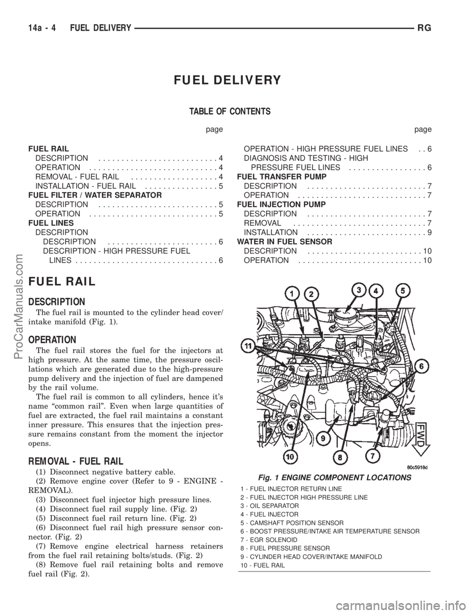
The fuel rail is mounted to the cylinder head cover/
intake manifold (Fig. 1).
OPERATION
The fuel rail stores the fuel for the injectors at
high pressure. At the same time, the pressure oscil-
lations which are generated due to the high-pressure
pump delivery and the injection of fuel are dampened
by the rail volume.
The fuel rail is common to all cylinders, hence it's
name ªcommon railº. Even when large quantities of
fuel are extracted, the fuel rail maintains a constant
inner pressure. This ensures that the injection pres-
sure remains constant from the moment the injector
opens.
REMOVAL - FUEL RAIL
(1) Disconnect negative battery cable.
(2) Remove engine cover (Refer to 9 - ENGINE -
REMOVAL).
(3) Disconnect fuel injector high pressure lines.
(4) Disconnect fuel rail supply line. (Fig. 2)
(5) Disconnect fuel rail return line. (Fig. 2)
(6) Disconnect fuel rail high pressure sensor con-
nector. (Fig. 2)
(7) Remove engine electrical harness retainers
from the fuel rail retaining bolts/studs. (Fig. 2)
(8) Remove fuel rail retaining bolts and remove
fuel rail (Fig. 2).Fig. 1 ENGINE COMPONENT LOCATIONS
1 - FUEL INJECTOR RETURN LINE
2 - FUEL INJECTOR HIGH PRESSURE LINE
3 - OIL SEPARATOR
4 - FUEL INJECTOR
5 - CAMSHAFT POSITION SENSOR
6 - BOOST PRESSURE/INTAKE AIR TEMPERATURE SENSOR
7 - EGR SOLENOID
8 - FUEL PRESSURE SENSOR
9 - CYLINDER HEAD COVER/INTAKE MANIFOLD
10 - FUEL RAIL
14a - 4 FUEL DELIVERYRG
ProCarManuals.com