2002 CHRYSLER VOYAGER electr
[x] Cancel search: electrPage 2007 of 2399
DOORS - SLIDING
TABLE OF CONTENTS
page page
CENTER HINGE
REMOVAL.............................24
INSTALLATION.........................24
SLIDING DOOR STOP BUMPER BEZEL
REMOVAL.............................25
INSTALLATION.........................25
STOP BUMPER
REMOVAL.............................25
INSTALLATION.........................25
HOLD OPEN LATCH
REMOVAL.............................25
INSTALLATION.........................25
HOLD OPEN LATCH STRIKER
REMOVAL.............................26
INSTALLATION.........................26
LATCH / LOCK ASSEMBLY
REMOVAL.............................26
INSTALLATION.........................26
CENTER STRIKER
REMOVAL.............................27
INSTALLATION.........................27
LOWER HINGE
REMOVAL.............................28
INSTALLATION.........................28
REAR LATCH STRIKER
REMOVAL.............................28
INSTALLATION.........................28
SLIDING DOOR
REMOVAL.............................29
INSTALLATION.........................29
ADJUSTMENTS
SLIDING DOOR ADJUSTMENTS..........30STABILIZER
REMOVAL.............................32
INSTALLATION.........................32
STABILIZER SOCKET
REMOVAL.............................33
INSTALLATION.........................33
TRIM PANEL
REMOVAL.............................33
INSTALLATION.........................33
INSIDE LATCH HANDLE
REMOVAL.............................33
INSTALLATION.........................34
BELLCRANK
REMOVAL.............................34
INSTALLATION.........................34
OUTSIDE HANDLE
REMOVAL.............................35
INSTALLATION.........................35
UPPER HINGE
REMOVAL.............................36
INSTALLATION.........................36
OUTSIDE HANDLE CABLE
REMOVAL.............................36
INSTALLATION.........................37
INSIDE HANDLE CABLE
REMOVAL.............................37
INSTALLATION.........................37
HOLD OPEN LATCH CABLE
REMOVAL.............................38
INSTALLATION.........................38
CENTER HINGE
REMOVAL
NOTE: For power sliding door procedures refer to
POWER SLIDING DOOR SYSTEM in the ELECTRI-
CAL section.
(1) Open sliding door to the mid point of its travel.
(2) Support sliding door on a suitable lifting
device.
(3) Mark outline of center hinge of inner door
panel to aid installation.
(4) Remove bolts attaching center hinge to sliding
door.(5) Remove center hinge from sliding door.
(6) Roll center hinge to rear of roller channel.
(7) Remove center hinge from vehicle.INSTALLATION
NOTE: For power sliding door procedures refer to
POWER SLIDING DOOR SYSTEM in the ELECTRI-
CAL section.
NOTE: Center hinge has an adjustable bolt for
up/down alignment. (Refer to 23 - BODY/DOORS -
SLIDING/SLIDING DOOR - ADJUSTMENTS)
(1) Place center hinge in position on vehicle.
23 - 24 DOORS - SLIDINGRS
ProCarManuals.com
Page 2009 of 2399
HOLD OPEN LATCH STRIKER
REMOVAL
NOTE: For power sliding door procedures refer to
POWER SLIDING DOOR SYSTEM in the ELECTRI-
CAL section.
(1) Open sliding door, do not latch open.
(2) Remove sliding door sill plate. (Refer to 23 -
BODY/INTERIOR/SLIDING DOOR SILL PLATE -
REMOVAL)
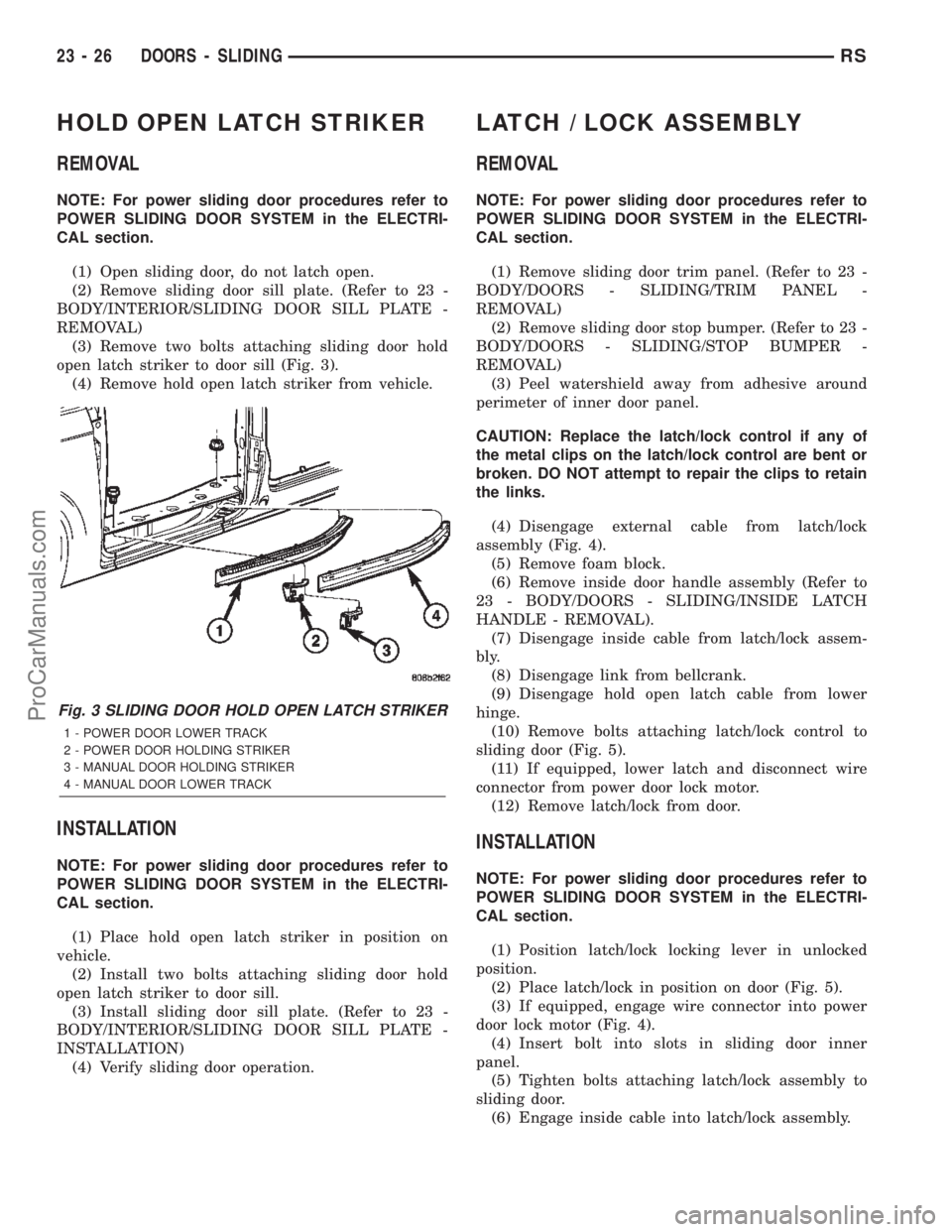
(3) Remove two bolts attaching sliding door hold
open latch striker to door sill (Fig. 3).
(4) Remove hold open latch striker from vehicle.
INSTALLATION
NOTE: For power sliding door procedures refer to
POWER SLIDING DOOR SYSTEM in the ELECTRI-
CAL section.
(1) Place hold open latch striker in position on
vehicle.
(2) Install two bolts attaching sliding door hold
open latch striker to door sill.
(3) Install sliding door sill plate. (Refer to 23 -
BODY/INTERIOR/SLIDING DOOR SILL PLATE -
INSTALLATION)
(4) Verify sliding door operation.
LATCH / LOCK ASSEMBLY
REMOVAL
NOTE: For power sliding door procedures refer to
POWER SLIDING DOOR SYSTEM in the ELECTRI-
CAL section.
(1) Remove sliding door trim panel. (Refer to 23 -
BODY/DOORS - SLIDING/TRIM PANEL -
REMOVAL)
(2) Remove sliding door stop bumper. (Refer to 23 -
BODY/DOORS - SLIDING/STOP BUMPER -
REMOVAL)
(3) Peel watershield away from adhesive around
perimeter of inner door panel.
CAUTION: Replace the latch/lock control if any of
the metal clips on the latch/lock control are bent or
broken. DO NOT attempt to repair the clips to retain
the links.
(4) Disengage external cable from latch/lock
assembly (Fig. 4).
(5) Remove foam block.
(6) Remove inside door handle assembly (Refer to
23 - BODY/DOORS - SLIDING/INSIDE LATCH
HANDLE - REMOVAL).
(7) Disengage inside cable from latch/lock assem-
bly.
(8) Disengage link from bellcrank.
(9) Disengage hold open latch cable from lower
hinge.
(10) Remove bolts attaching latch/lock control to
sliding door (Fig. 5).
(11) If equipped, lower latch and disconnect wire
connector from power door lock motor.
(12) Remove latch/lock from door.
INSTALLATION
NOTE: For power sliding door procedures refer to
POWER SLIDING DOOR SYSTEM in the ELECTRI-
CAL section.
(1) Position latch/lock locking lever in unlocked
position.
(2) Place latch/lock in position on door (Fig. 5).
(3) If equipped, engage wire connector into power
door lock motor (Fig. 4).
(4) Insert bolt into slots in sliding door inner
panel.
(5) Tighten bolts attaching latch/lock assembly to
sliding door.
(6) Engage inside cable into latch/lock assembly.
Fig. 3 SLIDING DOOR HOLD OPEN LATCH STRIKER
1 - POWER DOOR LOWER TRACK
2 - POWER DOOR HOLDING STRIKER
3 - MANUAL DOOR HOLDING STRIKER
4 - MANUAL DOOR LOWER TRACK
23 - 26 DOORS - SLIDINGRS
ProCarManuals.com
Page 2011 of 2399
(3) Install bolts attaching stop bumper.
(4) Install sliding door trim panel (Refer to 23 -
BODY/DOORS - SLIDING/TRIM PANEL - INSTAL-
LATION).
LOWER HINGE
REMOVAL
NOTE: For power sliding door procedures refer to
POWER SLIDING DOOR SYSTEM in the ELECTRI-
CAL section.
(1) Open sliding door.
(2) Mark outline of roller arm on sliding door to
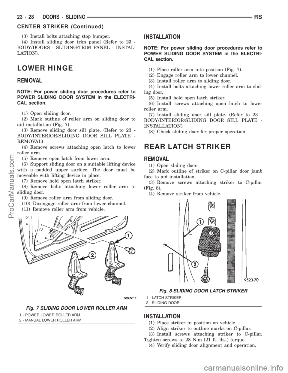
aid installation (Fig. 7).
(3) Remove sliding door sill plate. (Refer to 23 -
BODY/INTERIOR/SLIDING DOOR SILL PLATE -
REMOVAL)
(4) Remove screws attaching open latch to lower
roller arm.
(5) Remove open latch from lower arm.
(6) Support sliding door on a suitable lifting device
with a padded upper surface. The door must be
moveable with lifting device in place.
(7) Remove hold open latch striker.
(8) Remove bolts attaching lower roller arm to
sliding door.
(9) Remove roller arm from sliding door.
(10) Disengage roller arm from lower channel.
(11) Remove roller arm from vehicle.
INSTALLATION
NOTE: For power sliding door procedures refer to
POWER SLIDING DOOR SYSTEM in the ELECTRI-
CAL section.
(1) Place roller arm into position (Fig. 7).
(2) Engage roller arm to lower channel.
(3) Install roller arm to sliding door.
(4) Install bolts attaching lower roller arm to slid-
ing door.
(5) Install hold open latch striker.
(6) Install screws attaching open latch to lower
roller arm.
(7) Install sliding door sill plate. (Refer to 23 -
BODY/INTERIOR/SLIDING DOOR SILL PLATE -
INSTALLATION)
(8) Check sliding door for proper operation.
REAR LATCH STRIKER
REMOVAL
(1) Open sliding door.
(2) Mark outline of striker on C-pillar door jamb
face to aid installation.
(3) Remove screws attaching striker to C-pillar
(Fig. 8).
(4) Remove striker from vehicle.
INSTALLATION
(1) Place striker in position on vehicle.
(2) Align striker to outline marks on C-pillar.
(3) Install screws attaching striker to C-pillar.
Tighten screws to 28 N´m (21 ft. lbs.) torque.
(4) Verify sliding door alignment and operation.
Fig. 7 SLIDING DOOR LOWER ROLLER ARM
1 - POWER LOWER ROLLER ARM
2 - MANUAL LOWER ROLLER ARM
Fig. 8 SLIDING DOOR LATCH STRIKER
1 - LATCH STRIKER
2 - SLIDING DOOR
23 - 28 DOORS - SLIDINGRS
CENTER STRIKER (Continued)
ProCarManuals.com
Page 2012 of 2399
SLIDING DOOR
REMOVAL
NOTE: For power sliding door procedures refer to
POWER SLIDING DOOR SYSTEM in the ELECTRI-
CAL section.
(1) Apply masking tape to outside surface of quar-
ter panel below the center roller channel, rearward of
the door opening.
(2) Release sliding door latch and open door.
(3) Apply masking tape to door jamb area, rear-
ward of the upper roller channel.
(4) Remove screw attaching upper stop bumper to
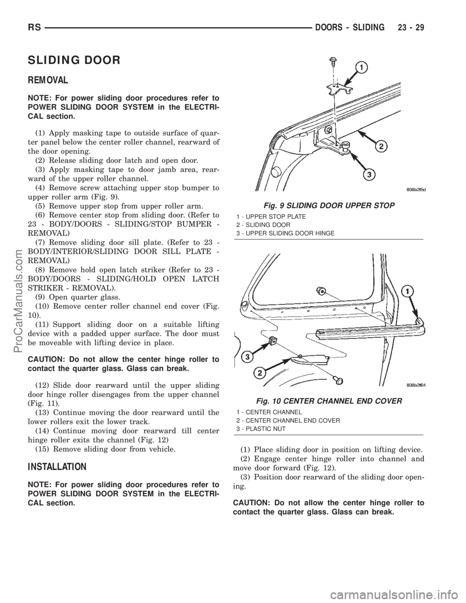
upper roller arm (Fig. 9).
(5) Remove upper stop from upper roller arm.
(6) Remove center stop from sliding door. (Refer to
23 - BODY/DOORS - SLIDING/STOP BUMPER -
REMOVAL)
(7) Remove sliding door sill plate. (Refer to 23 -
BODY/INTERIOR/SLIDING DOOR SILL PLATE -
REMOVAL)
(8) Remove hold open latch striker (Refer to 23 -
BODY/DOORS - SLIDING/HOLD OPEN LATCH
STRIKER - REMOVAL).
(9) Open quarter glass.
(10) Remove center roller channel end cover (Fig.
10).
(11) Support sliding door on a suitable lifting
device with a padded upper surface. The door must
be moveable with lifting device in place.
CAUTION: Do not allow the center hinge roller to
contact the quarter glass. Glass can break.
(12) Slide door rearward until the upper sliding
door hinge roller disengages from the upper channel
(Fig. 11).
(13) Continue moving the door rearward until the
lower rollers exit the lower track.
(14) Continue moving door rearward till center
hinge roller exits the channel (Fig. 12)
(15) Remove sliding door from vehicle.
INSTALLATION
NOTE: For power sliding door procedures refer to
POWER SLIDING DOOR SYSTEM in the ELECTRI-
CAL section.(1) Place sliding door in position on lifting device.
(2) Engage center hinge roller into channel and
move door forward (Fig. 12).
(3) Position door rearward of the sliding door open-
ing.
CAUTION: Do not allow the center hinge roller to
contact the quarter glass. Glass can break.
Fig. 9 SLIDING DOOR UPPER STOP
1 - UPPER STOP PLATE
2 - SLIDING DOOR
3 - UPPER SLIDING DOOR HINGE
Fig. 10 CENTER CHANNEL END COVER
1 - CENTER CHANNEL
2 - CENTER CHANNEL END COVER
3 - PLASTIC NUT
RSDOORS - SLIDING23-29
ProCarManuals.com
Page 2013 of 2399
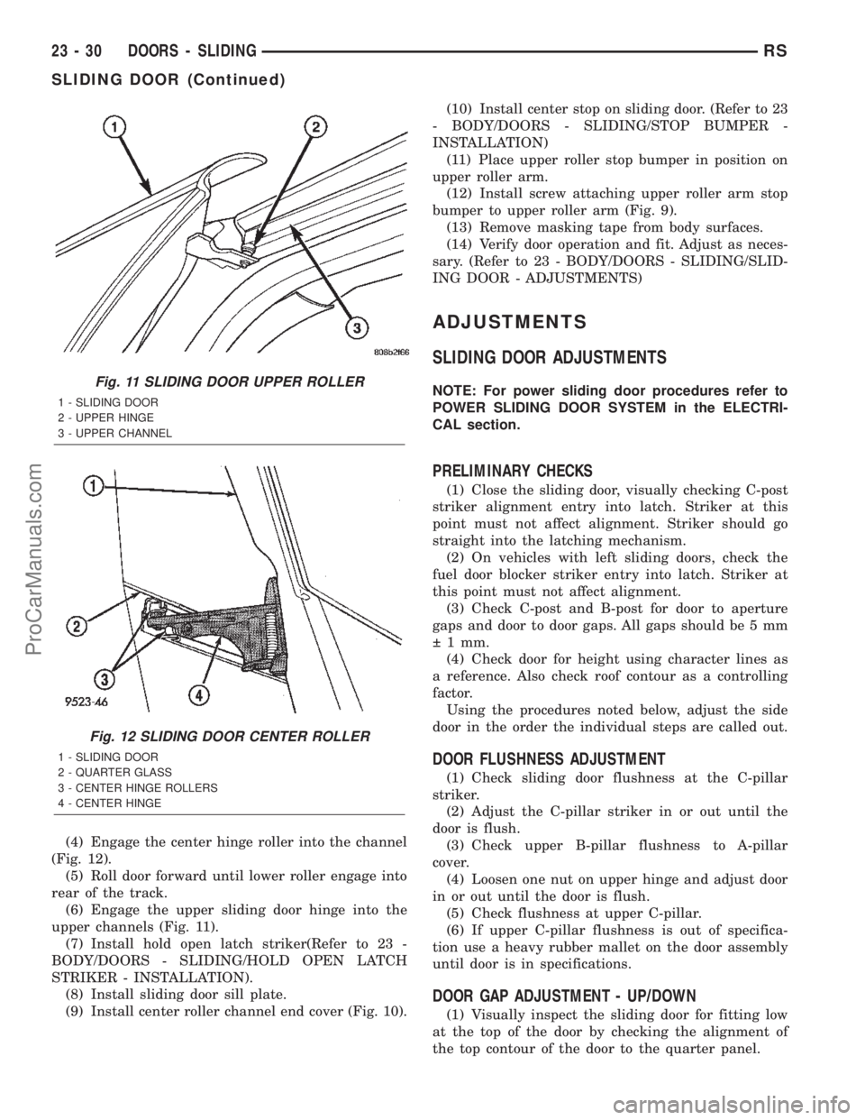
(4) Engage the center hinge roller into the channel
(Fig. 12).
(5) Roll door forward until lower roller engage into
rear of the track.
(6) Engage the upper sliding door hinge into the
upper channels (Fig. 11).
(7) Install hold open latch striker(Refer to 23 -
BODY/DOORS - SLIDING/HOLD OPEN LATCH
STRIKER - INSTALLATION).
(8) Install sliding door sill plate.
(9) Install center roller channel end cover (Fig. 10).(10) Install center stop on sliding door. (Refer to 23
- BODY/DOORS - SLIDING/STOP BUMPER -
INSTALLATION)
(11) Place upper roller stop bumper in position on
upper roller arm.
(12) Install screw attaching upper roller arm stop
bumper to upper roller arm (Fig. 9).
(13) Remove masking tape from body surfaces.
(14) Verify door operation and fit. Adjust as neces-
sary. (Refer to 23 - BODY/DOORS - SLIDING/SLID-
ING DOOR - ADJUSTMENTS)
ADJUSTMENTS
SLIDING DOOR ADJUSTMENTS
NOTE: For power sliding door procedures refer to
POWER SLIDING DOOR SYSTEM in the ELECTRI-
CAL section.
PRELIMINARY CHECKS
(1) Close the sliding door, visually checking C-post
striker alignment entry into latch. Striker at this
point must not affect alignment. Striker should go
straight into the latching mechanism.
(2) On vehicles with left sliding doors, check the
fuel door blocker striker entry into latch. Striker at
this point must not affect alignment.
(3) Check C-post and B-post for door to aperture
gaps and door to door gaps. All gaps should be 5 mm
1 mm.
(4) Check door for height using character lines as
a reference. Also check roof contour as a controlling
factor.
Using the procedures noted below, adjust the side
door in the order the individual steps are called out.
DOOR FLUSHNESS ADJUSTMENT
(1) Check sliding door flushness at the C-pillar
striker.
(2) Adjust the C-pillar striker in or out until the
door is flush.
(3) Check upper B-pillar flushness to A-pillar
cover.
(4) Loosen one nut on upper hinge and adjust door
in or out until the door is flush.
(5) Check flushness at upper C-pillar.
(6) If upper C-pillar flushness is out of specifica-
tion use a heavy rubber mallet on the door assembly
until door is in specifications.
DOOR GAP ADJUSTMENT - UP/DOWN
(1) Visually inspect the sliding door for fitting low
at the top of the door by checking the alignment of
the top contour of the door to the quarter panel.
Fig. 11 SLIDING DOOR UPPER ROLLER
1 - SLIDING DOOR
2 - UPPER HINGE
3 - UPPER CHANNEL
Fig. 12 SLIDING DOOR CENTER ROLLER
1 - SLIDING DOOR
2 - QUARTER GLASS
3 - CENTER HINGE ROLLERS
4 - CENTER HINGE
23 - 30 DOORS - SLIDINGRS
SLIDING DOOR (Continued)
ProCarManuals.com
Page 2019 of 2399
UPPER HINGE
REMOVAL
(1) Open sliding door, do not latch open.
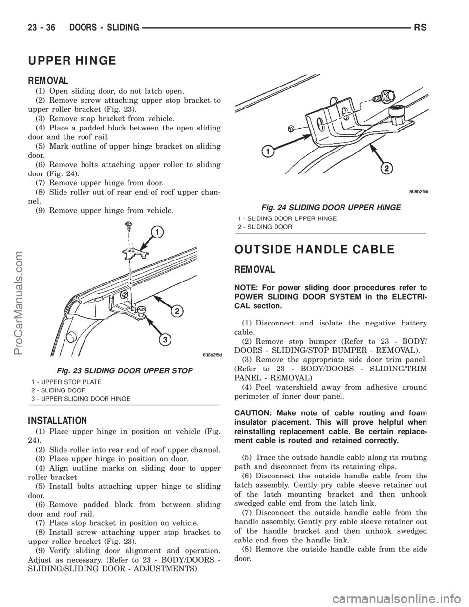
(2) Remove screw attaching upper stop bracket to
upper roller bracket (Fig. 23).
(3) Remove stop bracket from vehicle.
(4) Place a padded block between the open sliding
door and the roof rail.
(5) Mark outline of upper hinge bracket on sliding
door.
(6) Remove bolts attaching upper roller to sliding
door (Fig. 24).
(7) Remove upper hinge from door.
(8) Slide roller out of rear end of roof upper chan-
nel.
(9) Remove upper hinge from vehicle.
INSTALLATION
(1) Place upper hinge in position on vehicle (Fig.
24).
(2) Slide roller into rear end of roof upper channel.
(3) Place upper hinge in position on door.
(4) Align outline marks on sliding door to upper
roller bracket
(5) Install bolts attaching upper hinge to sliding
door.
(6) Remove padded block from between sliding
door and roof rail.
(7) Place stop bracket in position on vehicle.
(8) Install screw attaching upper stop bracket to
upper roller bracket (Fig. 23).
(9) Verify sliding door alignment and operation.
Adjust as necessary. (Refer to 23 - BODY/DOORS -
SLIDING/SLIDING DOOR - ADJUSTMENTS)
OUTSIDE HANDLE CABLE
REMOVAL
NOTE: For power sliding door procedures refer to
POWER SLIDING DOOR SYSTEM in the ELECTRI-
CAL section.
(1) Disconnect and isolate the negative battery
cable.
(2) Remove stop bumper (Refer to 23 - BODY/
DOORS - SLIDING/STOP BUMPER - REMOVAL).
(3) Remove the appropriate side door trim panel.
(Refer to 23 - BODY/DOORS - SLIDING/TRIM
PANEL - REMOVAL)
(4) Peel watershield away from adhesive around
perimeter of inner door panel.
CAUTION: Make note of cable routing and foam
insulator placement. This will prove helpful when
reinstalling replacement cable. Be certain replace-
ment cable is routed and retained correctly.
(5) Trace the outside handle cable along its routing
path and disconnect from its retaining clips.
(6) Disconnect the outside handle cable from the
latch assembly. Gently pry cable sleeve retainer out
of the latch mounting bracket and then unhook
swedged cable end from the latch link.
(7) Disconnect the outside handle cable from the
handle assembly. Gently pry cable sleeve retainer out
of the handle bracket and then unhook swedged
cable end from the handle link.
(8) Remove the outside handle cable from the side
door.
Fig. 23 SLIDING DOOR UPPER STOP
1 - UPPER STOP PLATE
2 - SLIDING DOOR
3 - UPPER SLIDING DOOR HINGE
Fig. 24 SLIDING DOOR UPPER HINGE
1 - SLIDING DOOR UPPER HINGE
2 - SLIDING DOOR
23 - 36 DOORS - SLIDINGRS
ProCarManuals.com
Page 2020 of 2399
INSTALLATION
NOTE: For power sliding door procedures refer to
POWER SLIDING DOOR SYSTEM in the ELECTRI-
CAL section.
(1) Match the replacement cable up against the old
cable to verify the correct part.
(2) Position the outside handle cable on the side
door.
(3) Connect the outside handle cable on the handle
assembly. Hook the swedged cable end on the handle
link and gently push the cable sleeve retainer in the
handle bracket.
NOTE: The outside handle cable is marked with red
tape. It must be attached to the latch at the lowest
point. This is marked with a ªRº on the latch.
(4) Connect the outside handle cable on the latch
assembly. Hook the swedged cable end on the latch
link and gently push the cable sleeve retainer in the
latch bracket.
(5) Trace the outside handle cable along its routing
path and install on its retaining clips and position
foam insulators. Use previously made schematic as a
guide or remove the opposite side door trim panel
and use that door as a guide.
CAUTION: Be certain replacement cable is routed
and retained correctly and foam insulators are
properly positioned.
(6) Place the watershield into position and press
securely to adhesive making sure to properly route
wiring and linkages.
(7) Install the appropriate side door trim panel on
the vehicle. (Refer to 23 - BODY/DOORS - SLIDING/
TRIM PANEL - INSTALLATION)
(8) Install stop bumper (Refer to 23 - BODY/
DOORS - SLIDING/STOP BUMPER - INSTALLA-
TION).
(9) Connect the negative battery cable.
INSIDE HANDLE CABLE
REMOVAL
NOTE: For power sliding door procedures refer to
POWER SLIDING DOOR SYSTEM in the ELECTRI-
CAL section.
(1) Disconnect and isolate the negative battery
cable.(2) Remove the appropriate side door trim panel
from the vehicle. (Refer to 23 - BODY/DOORS -
SLIDING/TRIM PANEL - REMOVAL)
(3) Peel watershield away from adhesive around
perimeter of inner door panel.
(4) Remove the inside handle assembly from the
side door. (Refer to 23 - BODY/DOORS - SLIDING/
INSIDE LATCH HANDLE - REMOVAL)
(5) Disconnect the inside handle cable from the
handle assembly. Gently pry cable sleeve retainer out
of the handle bracket and then unhook swedged
cable end from the handle link.
(6) Open the side door and remove the latch
assembly. Refer to the Power Side Doors section for
the procedure.
CAUTION: Make note of cable routing and foam
insulator placement. This will prove helpful when
reinstalling replacement cable. Be certain replace-
ment cable is routed and retained correctly.
(7) Trace the inside handle cable along its routing
path and disconnect from its retaining clips.
(8) Disconnect the inside handle cable from the
latch assembly. Gently pry cable sleeve retainer out
of the latch mounting bracket and then unhook
swedged cable end from the latch link.
(9) Remove the inside handle cable from the side
door.
INSTALLATION
NOTE: For power sliding door procedures refer to
POWER SLIDING DOOR SYSTEM in the ELECTRI-
CAL section.
(1) Match the replacement cable up against the old
cable to verify the correct part.
(2) Position the inside handle cable on the side
door.
(3) Connect the inside handle cable on the handle
assembly. Hook the swedged cable end on the handle
link and gently push the cable sleeve retainer in the
handle bracket.
(4) Install the inside handle assembly on the side
door. (Refer to 23 - BODY/DOORS - SLIDING/IN-
SIDE LATCH HANDLE - INSTALLATION)
NOTE: The inside handle cable is marked with blue
tape and must be attached to the latch at the center
(just above the lower cable). This position is
marked with a ªBº on the latch.
(5) Connect the inside handle cable on the latch
assembly. Hook the swedged cable end on the latch
link and gently push the cable sleeve retainer in the
latch bracket.
RSDOORS - SLIDING23-37
OUTSIDE HANDLE CABLE (Continued)
ProCarManuals.com
Page 2021 of 2399
(6) Trace the inside handle cable along its routing
path and install on its retaining clips and position
foam insulators. Use previously made schematic as a
guide or remove the opposite side door trim panel
and use that door as a guide.
CAUTION: Be certain replacement cable is routed
and retained correctly and foam insulators are
properly positioned.
(7) Install the latch assembly. Refer to the Power
Side Doors section for the procedure.
(8) Place the watershield into position and press
securely to adhesive making sure to properly route
wiring and linkages.
(9) Install the appropriate side door trim panel on
the vehicle. (Refer to 23 - BODY/DOORS - SLIDING/
TRIM PANEL - INSTALLATION)
(10) Connect the negative battery cable.
HOLD OPEN LATCH CABLE
REMOVAL
NOTE: For power sliding door procedures refer to
POWER SLIDING DOOR SYSTEM in the ELECTRI-
CAL section.
(1) Disconnect and isolate the negative battery
cable.
(2) Remove the appropriate side door trim panel
from the vehicle. (Refer to 23 - BODY/DOORS -
SLIDING/TRIM PANEL - REMOVAL)
(3) Peel watershield away from adhesive around
perimeter of inner door panel.
(4) Open the side door and remove the latch
assembly. (Refer to 8 - ELECTRICAL/POWER
DOORS/LATCH - REMOVAL)
CAUTION: Make note of cable routing and foam
insulator placement. This will prove helpful when
reinstalling replacement cable. Be certain replace-
ment cable is routed and retained correctly.
(5) Trace the hold open latch cable along its rout-
ing path and disconnect from its retaining clips.
(6) Disconnect the hold open latch cable from the
latch assembly. Gently pry cable sleeve retainer out
of the latch mounting bracket and then unhook
swedged cable end from the latch link.
(7) Remove the hold open latch from the side door.
(Refer to 23 - BODY/DOORS - SLIDING/HOLD
OPEN LATCH - REMOVAL)
(8) Disconnect the hold open latch cable from the
hold open latch. Gently pry cable sleeve retainer outof the handle bracket and then unhook swedged
cable end from the latch link.
(9) Remove the hold open latch cable from the side
door.
INSTALLATION
NOTE: For power sliding door procedures refer to
POWER SLIDING DOOR SYSTEM in the ELECTRI-
CAL section.
(1) Match the replacement cable up against the old
cable to verify the correct part.
(2) Position the hold open latch cable on the side
door.
NOTE: The hold open latch cable is marked with
white tape. It must be attached to the upper most
cable attachment at the latch. This position is
marked with a ªWº on the latch.
(3) Connect the hold open latch cable on the hold
open latch assembly. Hook the swedged cable end on
the latch link and gently push the cable sleeve
retainer in the latch bracket.
(4) Install the hold open latch on the side door.(Re-
fer to 23 - BODY/DOORS - SLIDING/HOLD OPEN
LATCH - INSTALLATION)
(5) Connect the hold open latch cable on the latch
assembly. Hook the swedged cable end on the latch
link and gently push the cable sleeve retainer in the
latch bracket.
(6) Trace the outside handle cable along its routing
path and install on its retaining clips and position
foam insulators. Use previously made schematic as a
guide or remove the opposite side door trim panel
and use that door as a guide.
CAUTION: Be certain replacement cable is routed
and retained correctly and foam insulators are
properly positioned.
(7) Install the latch assembly. (Refer to 8 - ELEC-
TRICAL/POWER DOORS/LATCH - INSTALLATION)
(8) Place the watershield into position and press
securely to adhesive making sure to properly route
wiring and linkages.
(9) Install the appropriate side door trim panel on
the vehicle. (Refer to 23 - BODY/DOORS - SLIDING/
TRIM PANEL - INSTALLATION)
(10) Connect the negative battery cable.
23 - 38 DOORS - SLIDINGRS
INSIDE HANDLE CABLE (Continued)
ProCarManuals.com