2002 CHRYSLER VOYAGER electr
[x] Cancel search: electrPage 1679 of 2399
ADJUSTMENTS
THROTTLE VALVE LINKAGE ADJUSTMENT
The throttle valve linkage adjustment is very
important to proper transaxle operation. This adjust-
ment positions a valve which controls shift speed,
shift quality, and part throttle downshift sensitivity.
If the setting is too short, early shifts and slippage
between shifts may occur. If the setting is too long,
shifts may be delayed and part throttle downshifts
may be very sensitive.
LINKAGE ADJUSTMENT PROCEDURE
(1) Perform transaxle throttle valve linkage
adjustment while engine is at normal operating tem-
perature.
(2) Using small screwdriver, disengage adjustment
lock at transaxle.
(3) Rotate lever at transaxle all the way to the left
side of vehicle against stop.
(4) Slide cable adjuster until cable core end
touches clip at throttle valve lever.
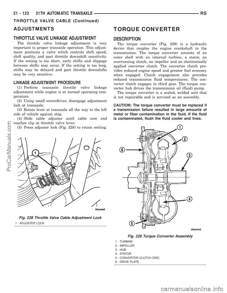
(5) Press adjuster lock (Fig. 228) to retain setting.
TORQUE CONVERTER
DESCRIPTION
The torque converter (Fig. 229) is a hydraulic
device that couples the engine crankshaft to the
transmission. The torque converter consists of an
outer shell with an internal turbine, a stator, an
overrunning clutch, an impeller and an electronically
applied converter clutch. The converter clutch pro-
vides reduced engine speed and greater fuel economy
when engaged. Clutch engagement also provides
reduced transmission fluid temperatures. The con-
verter clutch engages in third gear. The torque con-
verter hub drives the transmission oil (fluid) pump.
The torque converter is a sealed, welded unit that
is not repairable and is serviced as an assembly.
CAUTION: The torque converter must be replaced if
a transmission failure resulted in large amounts of
metal or fiber contamination in the fluid. If the fluid
is contaminated, flush the fluid cooler and lines.
Fig. 228 Throttle Valve Cable Adjustment Lock
1 - ADJUSTER LOCK
Fig. 229 Torque Converter Assembly
1 - TURBINE
2 - IMPELLER
3 - HUB
4-STATOR
5 - CONVERTER CLUTCH DISC
6 - DRIVE PLATE
21 - 122 31TH AUTOMATIC TRANSAXLERS
THROTTLE VALVE CABLE (Continued)
ProCarManuals.com
Page 1719 of 2399
OPERATION..........................292
REMOVAL............................292
INSTALLATION........................292
TRD LINK
DESCRIPTION........................292
OPERATION..........................292
VALVE BODY
DESCRIPTION........................293OPERATION..........................293
REMOVAL
REMOVAL..........................294
REMOVAL..........................296
DISASSEMBLY........................297
ASSEMBLY...........................301
INSTALLATION........................306
41TE AUTOMATIC
TRANSAXLE
DESCRIPTION
The 41TE (Fig. 1) is a four-speed transaxle that is
a conventional hydraulic/mechanical assembly with
an integral differential, and is controlled with adap-
tive electronic controls and monitors. The hydraulic
system of the transaxle consists of the transaxle
fluid, fluid passages, hydraulic valves, and various
line pressure control components. An input clutch
assembly which houses the underdrive, overdrive,
and reverse clutches is used. It also utilizes separate
holding clutches: 2nd/4th gear and Low/Reverse. The
primary mechanical components of the transaxle con-
sist of the following:
²Three multiple disc input clutches
²Two multiple disc holding clutches
²Four hydraulic accumulators
²Two planetary gear sets
²Hydraulic oil pump²Valve body
²Solenoid/Pressure switch assembly
²Integral differential assembly
Control of the transaxle is accomplished by fully
adaptive electronics. Optimum shift scheduling is
accomplished through continuous real-time sensor
feedback information provided to the Transmission
Control Module (TCM).
The TCM is the heart of the electronic control sys-
tem and relies on information from various direct
and indirect inputs (sensors, switches, etc.) to deter-
mine driver demand and vehicle operating condi-
tions. With this information, the TCM can calculate
and perform timely and quality shifts through vari-
ous output or control devices (solenoid pack, trans-
mission control relay, etc.).
The TCM also performs certain self-diagnostic
functions and provides comprehensive information
(sensor data, DTC's, etc.) which is helpful in proper
diagnosis and repair. This information can be viewed
with the DRB scan tool.
21 - 162 41TE AUTOMATIC TRANSAXLERS
ProCarManuals.com
Page 1721 of 2399
TRANSAXLE IDENTIFICATION
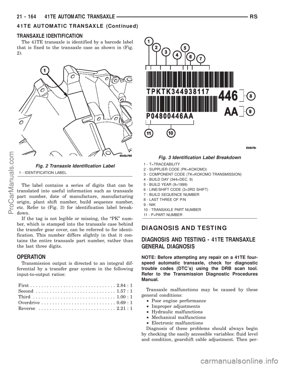
The 41TE transaxle is identified by a barcode label
that is fixed to the transaxle case as shown in (Fig.
2).
The label contains a series of digits that can be
translated into useful information such as transaxle
part number, date of manufacture, manufacturing
origin, plant shift number, build sequence number,
etc. Refer to (Fig. 3) for identification label break-
down.
If the tag is not legible or missing, the ªPKº num-
ber, which is stamped into the transaxle case behind
the transfer gear cover, can be referred to for identi-
fication. This number differs slightly in that it con-
tains the entire transaxle part number, rather than
the last three digits.
OPERATION
Transmission output is directed to an integral dif-
ferential by a transfer gear system in the following
input-to-output ratios:
First...............................2.84 : 1
Second.............................1.57 : 1
Third..............................1.00 : 1
Overdrive...........................0.69 : 1
Reverse............................2.21 : 1
DIAGNOSIS AND TESTING
DIAGNOSIS AND TESTING - 41TE TRANSAXLE
GENERAL DIAGNOSIS
NOTE: Before attempting any repair on a 41TE four-
speed automatic transaxle, check for diagnostic
trouble codes (DTC's) using the DRB scan tool.
Refer to the Transmission Diagnostic Procedures
Manual.
Transaxle malfunctions may be caused by these
general conditions:
²Poor engine performance
²Improper adjustments
²Hydraulic malfunctions
²Mechanical malfunctions
²Electronic malfunctions
Diagnosis of these problems should always begin
by checking the easily accessible variables: fluid level
and condition, gearshift cable adjustment. Then per-
Fig. 2 Transaxle Identification Label
1 - IDENTIFICATION LABEL
Fig. 3 Identification Label Breakdown
1 - T=TRACEABILITY
2 - SUPPLIER CODE (PK=KOKOMO)
3 - COMPONENT CODE (TK=KOKOMO TRANSMISSION)
4 - BUILD DAY (344=DEC. 9)
5 - BUILD YEAR (9=1999)
6 - LINE/SHIFT CODE (3=3RD SHIFT)
7 - BUILD SEQUENCE NUMBER
8 - LAST THREE OF P/N
9 - NIK
10 - TRANSAXLE PART NUMBER
11 - P=PART NUMBER
21 - 164 41TE AUTOMATIC TRANSAXLERS
41TE AUTOMATIC TRANSAXLE (Continued)
ProCarManuals.com
Page 1726 of 2399
Converter housing leaks have several potential
sources. Through careful observation, a leak source
can be identified before removing the transmission
for repair.
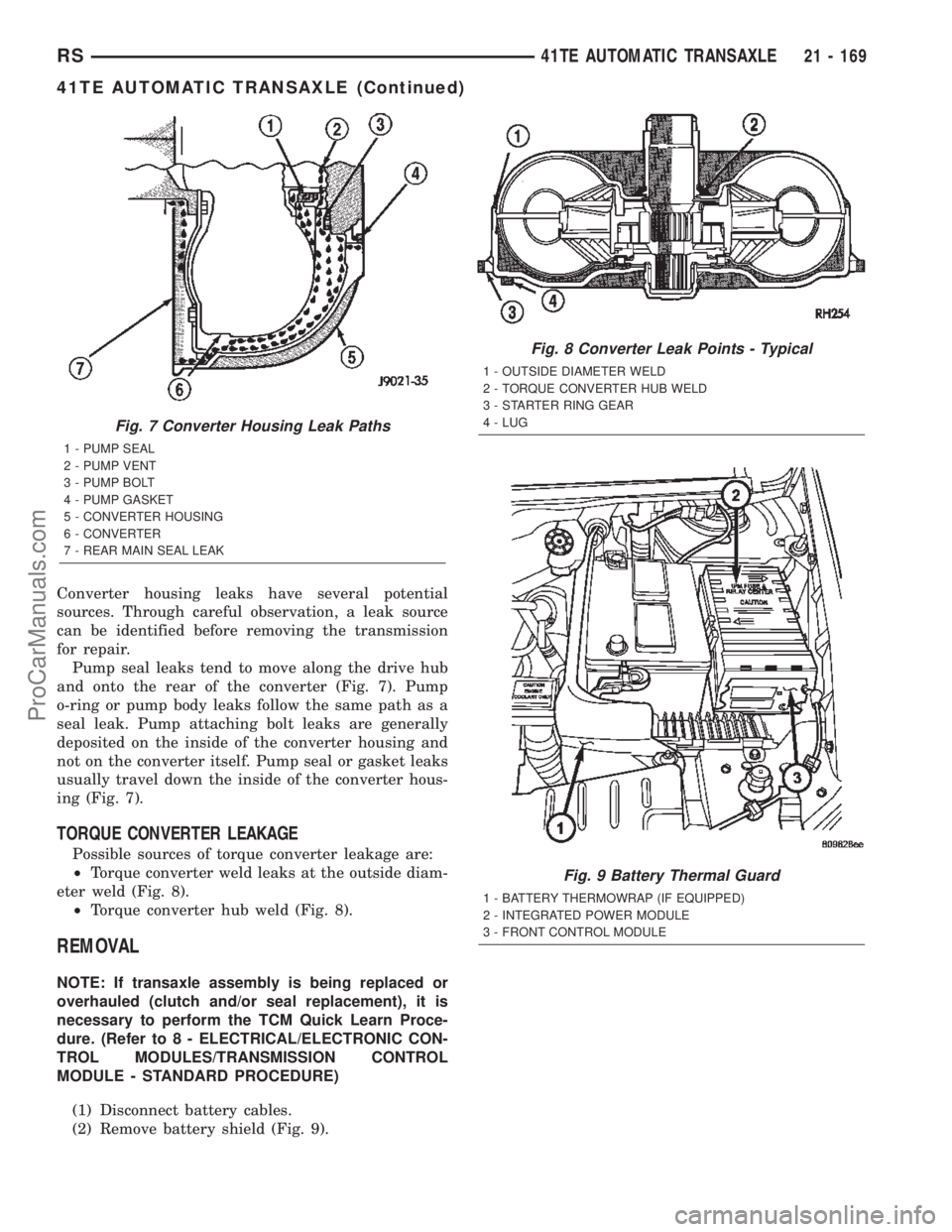
Pump seal leaks tend to move along the drive hub
and onto the rear of the converter (Fig. 7). Pump
o-ring or pump body leaks follow the same path as a
seal leak. Pump attaching bolt leaks are generally
deposited on the inside of the converter housing and
not on the converter itself. Pump seal or gasket leaks
usually travel down the inside of the converter hous-
ing (Fig. 7).
TORQUE CONVERTER LEAKAGE
Possible sources of torque converter leakage are:
²Torque converter weld leaks at the outside diam-
eter weld (Fig. 8).
²Torque converter hub weld (Fig. 8).
REMOVAL
NOTE: If transaxle assembly is being replaced or
overhauled (clutch and/or seal replacement), it is
necessary to perform the TCM Quick Learn Proce-
dure. (Refer to 8 - ELECTRICAL/ELECTRONIC CON-
TROL MODULES/TRANSMISSION CONTROL
MODULE - STANDARD PROCEDURE)
(1) Disconnect battery cables.
(2) Remove battery shield (Fig. 9).
Fig. 7 Converter Housing Leak Paths
1 - PUMP SEAL
2 - PUMP VENT
3 - PUMP BOLT
4 - PUMP GASKET
5 - CONVERTER HOUSING
6 - CONVERTER
7 - REAR MAIN SEAL LEAK
Fig. 8 Converter Leak Points - Typical
1 - OUTSIDE DIAMETER WELD
2 - TORQUE CONVERTER HUB WELD
3 - STARTER RING GEAR
4 - LUG
Fig. 9 Battery Thermal Guard
1 - BATTERY THERMOWRAP (IF EQUIPPED)
2 - INTEGRATED POWER MODULE
3 - FRONT CONTROL MODULE
RS41TE AUTOMATIC TRANSAXLE21 - 169
41TE AUTOMATIC TRANSAXLE (Continued)
ProCarManuals.com
Page 1728 of 2399
(18) AWD models: Remove power transfer unit.
(Refer to 21 - TRANSMISSION/TRANSAXLE/
POWER TRANSFER UNIT - REMOVAL)
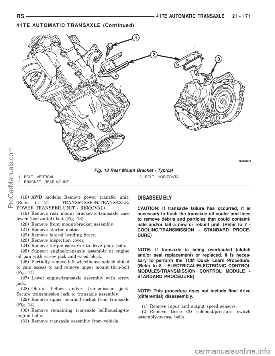
(19) Remove rear mount bracket-to-transaxle case
lower (horizontal) bolt (Fig. 13).
(20) Remove front mount/bracket assembly.
(21) Remove starter motor.
(22) Remove lateral bending brace.
(23) Remove inspection cover.
(24) Remove torque converter-to-drive plate bolts.
(25) Support engine/transaxle assembly at engine
oil pan with screw jack and wood block.
(26) Partially remove left wheelhouse splash shield
to gain access to and remove upper mount thru-bolt
(Fig. 14).
(27) Lower engine/transaxle assembly with screw
jack.
(28) Obtain helper and/or transmission jack.
Secure transmission jack to transaxle assembly.
(29) Remove upper mount bracket from transaxle
(Fig. 14).
(30) Remove remaining transaxle bellhousing-to-
engine bolts.
(31) Remove transaxle assembly from vehicle.DISASSEMBLY
CAUTION: If transaxle failure has occurred, it is
necessary to flush the transaxle oil cooler and lines
to remove debris and particles that could contami-
nate and/or fail a new or rebuilt unit. (Refer to 7 -
COOLING/TRANSMISSION - STANDARD PROCE-
DURE)
NOTE: If transaxle is being overhauled (clutch
and/or seal replacement) or replaced, it is neces-
sary to perform the TCM Quick Learn Procedure.
(Refer to 8 - ELECTRICAL/ELECTRONIC CONTROL
MODULES/TRANSMISSION CONTROL MODULE -
STANDARD PROCEDURE)
NOTE: This procedure does not include final drive
(differential) disassembly.
(1) Remove input and output speed sensors.
(2) Remove three (3) solenoid/pressure switch
assembly-to-case bolts.
Fig. 13 Rear Mount Bracket - Typical
1 - BOLT - VERTICAL
2 - BRACKET - REAR MOUNT3 - BOLT - HORIZONTAL
RS41TE AUTOMATIC TRANSAXLE21 - 171
41TE AUTOMATIC TRANSAXLE (Continued)
ProCarManuals.com
Page 1747 of 2399
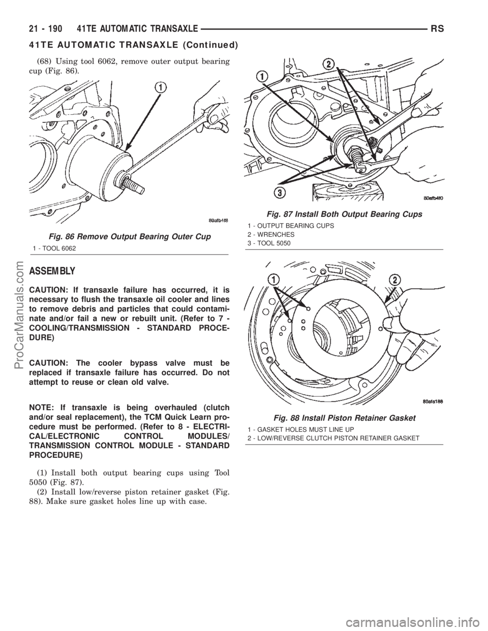
(68) Using tool 6062, remove outer output bearing
cup (Fig. 86).
ASSEMBLY
CAUTION: If transaxle failure has occurred, it is
necessary to flush the transaxle oil cooler and lines
to remove debris and particles that could contami-
nate and/or fail a new or rebuilt unit. (Refer to 7 -
COOLING/TRANSMISSION - STANDARD PROCE-
DURE)
CAUTION: The cooler bypass valve must be
replaced if transaxle failure has occurred. Do not
attempt to reuse or clean old valve.
NOTE: If transaxle is being overhauled (clutch
and/or seal replacement), the TCM Quick Learn pro-
cedure must be performed. (Refer to 8 - ELECTRI-
CAL/ELECTRONIC CONTROL MODULES/
TRANSMISSION CONTROL MODULE - STANDARD
PROCEDURE)
(1) Install both output bearing cups using Tool
5050 (Fig. 87).
(2) Install low/reverse piston retainer gasket (Fig.
88). Make sure gasket holes line up with case.
Fig. 86 Remove Output Bearing Outer Cup
1 - TOOL 6062
Fig. 87 Install Both Output Bearing Cups
1 - OUTPUT BEARING CUPS
2 - WRENCHES
3 - TOOL 5050
Fig. 88 Install Piston Retainer Gasket
1 - GASKET HOLES MUST LINE UP
2 - LOW/REVERSE CLUTCH PISTON RETAINER GASKET
21 - 190 41TE AUTOMATIC TRANSAXLERS
41TE AUTOMATIC TRANSAXLE (Continued)
ProCarManuals.com
Page 1770 of 2399
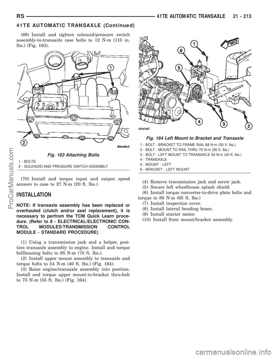
(69) Install and tighten solenoid/pressure switch
assembly-to-transaxle case bolts to 12 N´m (110 in.
lbs.) (Fig. 163).
(70) Install and torque input and output speed
sensors to case to 27 N´m (20 ft. lbs.).
INSTALLATION
NOTE: If transaxle assembly has been replaced or
overhauled (clutch and/or seal replacement), it is
necessary to perfrom the TCM Quick Learn proce-
dure. (Refer to 8 - ELECTRICAL/ELECTRONIC CON-
TROL MODULES/TRANSMISSION CONTROL
MODULE - STANDARD PROCEDURE)
(1) Using a transmission jack and a helper, posi-
tion transaxle assembly to engine. Install and torque
bellhousing bolts to 95 N´m (70 ft. lbs.).
(2) Install upper mount assembly to transaxle and
torque bolts to 54 N´m (40 ft. lbs.) (Fig. 164).
(3) Raise engine/transaxle assembly into position.
Install and torque upper mount-to-bracket thru-bolt
to 75 N´m (55 ft. lbs.) (Fig. 164).(4) Remove transmission jack and screw jack.
(5) Secure left wheelhouse splash shield.
(6) Install torque converter-to-drive plate bolts and
torque to 88 N´m (65 ft. lbs.)
(7) Install inspection cover.
(8) Install lateral bending brace.
(9) Install starter motor.
(10) Install front mount/bracket assembly.
Fig. 163 Attaching Bolts
1 - BOLTS
2 - SOLENOID AND PRESSURE SWITCH ASSEMBLY
Fig. 164 Left Mount to Bracket and Transaxle
1 - BOLT - BRACKET TO FRAME RAIL 68 N´m (50 ft. lbs.)
2 - BOLT - MOUNT TO RAIL THRU 75 N´m (55 ft. lbs.)
3 - BOLT - LEFT MOUNT TO TRANSAXLE 54 N´m (40 ft. lbs.)
4 - TRANSAXLE
5 - MOUNT - LEFT
6 - BRACKET - LEFT MOUNT
RS41TE AUTOMATIC TRANSAXLE21 - 213
41TE AUTOMATIC TRANSAXLE (Continued)
ProCarManuals.com
Page 1785 of 2399
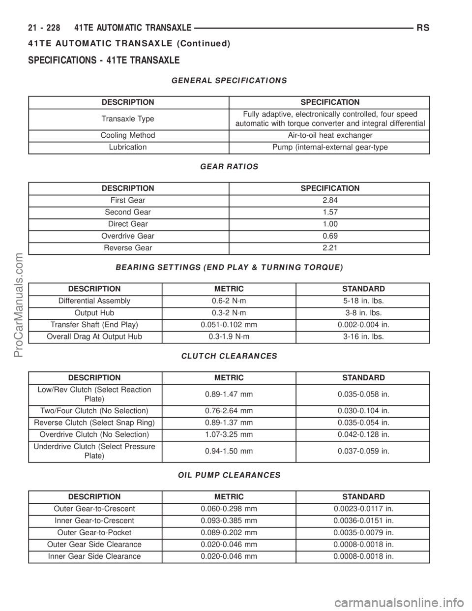
SPECIFICATIONS - 41TE TRANSAXLE
GENERAL SPECIFICATIONS
DESCRIPTION SPECIFICATION
Transaxle TypeFully adaptive, electronically controlled, four speed
automatic with torque converter and integral differential
Cooling Method Air-to-oil heat exchanger
Lubrication Pump (internal-external gear-type
GEAR RATIOS
DESCRIPTION SPECIFICATION
First Gear 2.84
Second Gear 1.57
Direct Gear 1.00
Overdrive Gear 0.69
Reverse Gear 2.21
BEARING SETTINGS (END PLAY & TURNING TORQUE)
DESCRIPTION METRIC STANDARD
Differential Assembly 0.6-2 N´m 5-18 in. lbs.
Output Hub 0.3-2 N´m 3-8 in. lbs.
Transfer Shaft (End Play) 0.051-0.102 mm 0.002-0.004 in.
Overall Drag At Output Hub 0.3-1.9 N´m 3-16 in. lbs.
CLUTCH CLEARANCES
DESCRIPTION METRIC STANDARD
Low/Rev Clutch (Select Reaction
Plate)0.89-1.47 mm 0.035-0.058 in.
Two/Four Clutch (No Selection) 0.76-2.64 mm 0.030-0.104 in.
Reverse Clutch (Select Snap Ring) 0.89-1.37 mm 0.035-0.054 in.
Overdrive Clutch (No Selection) 1.07-3.25 mm 0.042-0.128 in.
Underdrive Clutch (Select Pressure
Plate)0.94-1.50 mm 0.037-0.059 in.
OIL PUMP CLEARANCES
DESCRIPTION METRIC STANDARD
Outer Gear-to-Crescent 0.060-0.298 mm 0.0023-0.0117 in.
Inner Gear-to-Crescent 0.093-0.385 mm 0.0036-0.0151 in.
Outer Gear-to-Pocket 0.089-0.202 mm 0.0035-0.0079 in.
Outer Gear Side Clearance 0.020-0.046 mm 0.0008-0.0018 in.
Inner Gear Side Clearance 0.020-0.046 mm 0.0008-0.0018 in.
21 - 228 41TE AUTOMATIC TRANSAXLERS
41TE AUTOMATIC TRANSAXLE (Continued)
ProCarManuals.com