2002 CHRYSLER TOWN AND COUNTRY timing
[x] Cancel search: timingPage 1279 of 2399
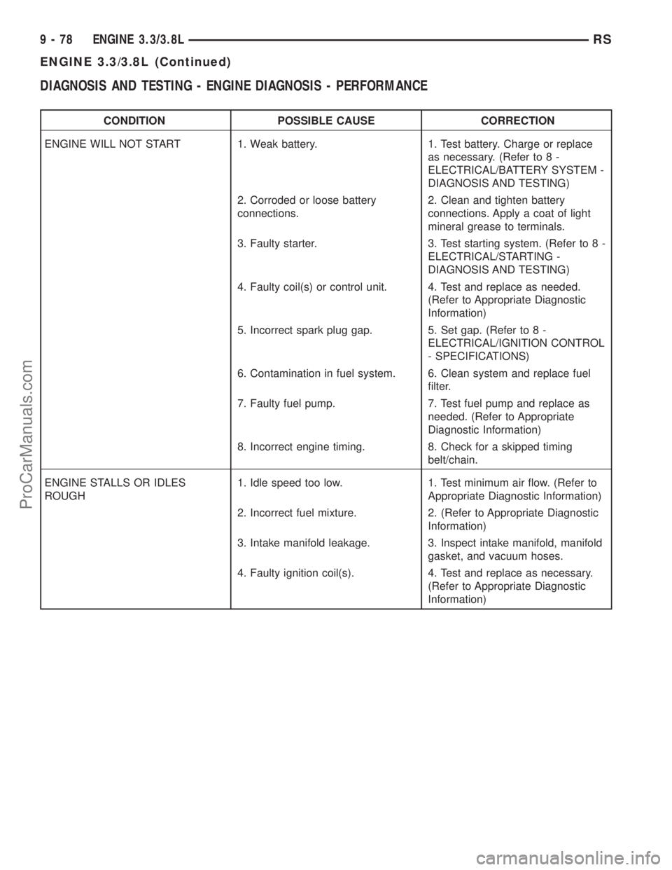
DIAGNOSIS AND TESTING - ENGINE DIAGNOSIS - PERFORMANCE
CONDITION POSSIBLE CAUSE CORRECTION
ENGINE WILL NOT START 1. Weak battery. 1. Test battery. Charge or replace
as necessary. (Refer to 8 -
ELECTRICAL/BATTERY SYSTEM -
DIAGNOSIS AND TESTING)
2. Corroded or loose battery
connections.2. Clean and tighten battery
connections. Apply a coat of light
mineral grease to terminals.
3. Faulty starter. 3. Test starting system. (Refer to 8 -
ELECTRICAL/STARTING -
DIAGNOSIS AND TESTING)
4. Faulty coil(s) or control unit. 4. Test and replace as needed.
(Refer to Appropriate Diagnostic
Information)
5. Incorrect spark plug gap. 5. Set gap. (Refer to 8 -
ELECTRICAL/IGNITION CONTROL
- SPECIFICATIONS)
6. Contamination in fuel system. 6. Clean system and replace fuel
filter.
7. Faulty fuel pump. 7. Test fuel pump and replace as
needed. (Refer to Appropriate
Diagnostic Information)
8. Incorrect engine timing. 8. Check for a skipped timing
belt/chain.
ENGINE STALLS OR IDLES
ROUGH1. Idle speed too low. 1. Test minimum air flow. (Refer to
Appropriate Diagnostic Information)
2. Incorrect fuel mixture. 2. (Refer to Appropriate Diagnostic
Information)
3. Intake manifold leakage. 3. Inspect intake manifold, manifold
gasket, and vacuum hoses.
4. Faulty ignition coil(s). 4. Test and replace as necessary.
(Refer to Appropriate Diagnostic
Information)
9 - 78 ENGINE 3.3/3.8LRS
ENGINE 3.3/3.8L (Continued)
ProCarManuals.com
Page 1280 of 2399
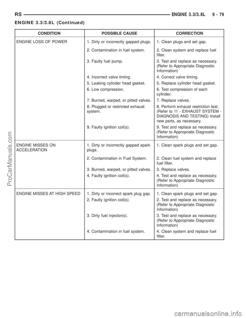
CONDITION POSSIBLE CAUSE CORRECTION
ENGINE LOSS OF POWER 1. Dirty or incorrectly gapped plugs. 1. Clean plugs and set gap.
2. Contamination in fuel system. 2. Clean system and replace fuel
filter.
3. Faulty fuel pump. 3. Test and replace as necessary.
(Refer to Appropriate Diagnostic
Information)
4. Incorrect valve timing. 4. Correct valve timing.
5. Leaking cylinder head gasket. 5. Replace cylinder head gasket.
6. Low compression. 6. Test compression of each
cylinder.
7. Burned, warped, or pitted valves. 7. Replace valves.
8. Plugged or restricted exhaust
system.8. Perform exhaust restriction test.
(Refer to 11 - EXHAUST SYSTEM -
DIAGNOSIS AND TESTING) Install
new parts, as necessary.
9. Faulty ignition coil(s). 9. Test and replace as necessary.
(Refer to Appropriate Diagnostic
Information)
ENGINE MISSES ON
ACCELERATION1. Dirty or incorrectly gapped spark
plugs.1. Clean spark plugs and set gap.
2. Contamination in Fuel System. 2. Clean fuel system and replace
fuel filter.
3. Burned, warped, or pitted valves. 3. Replace valves.
4. Faulty ignition coil(s). 4. Test and replace as necessary.
(Refer to Appropriate Diagnostic
Information)
ENGINE MISSES AT HIGH SPEED 1. Dirty or incorrect spark plug gap. 1. Clean spark plugs and set gap.
2. Faulty ignition coil(s). 2. Test and replace as necessary.
(Refer to Appropriate Diagnostic
Information)
3. Dirty fuel injector(s). 3. Test and replace as necessary.
(Refer to Appropriate Diagnostic
Information)
4. Contamination in fuel system. 4. Clean system and replace fuel
filter.
RSENGINE 3.3/3.8L9-79
ENGINE 3.3/3.8L (Continued)
ProCarManuals.com
Page 1295 of 2399
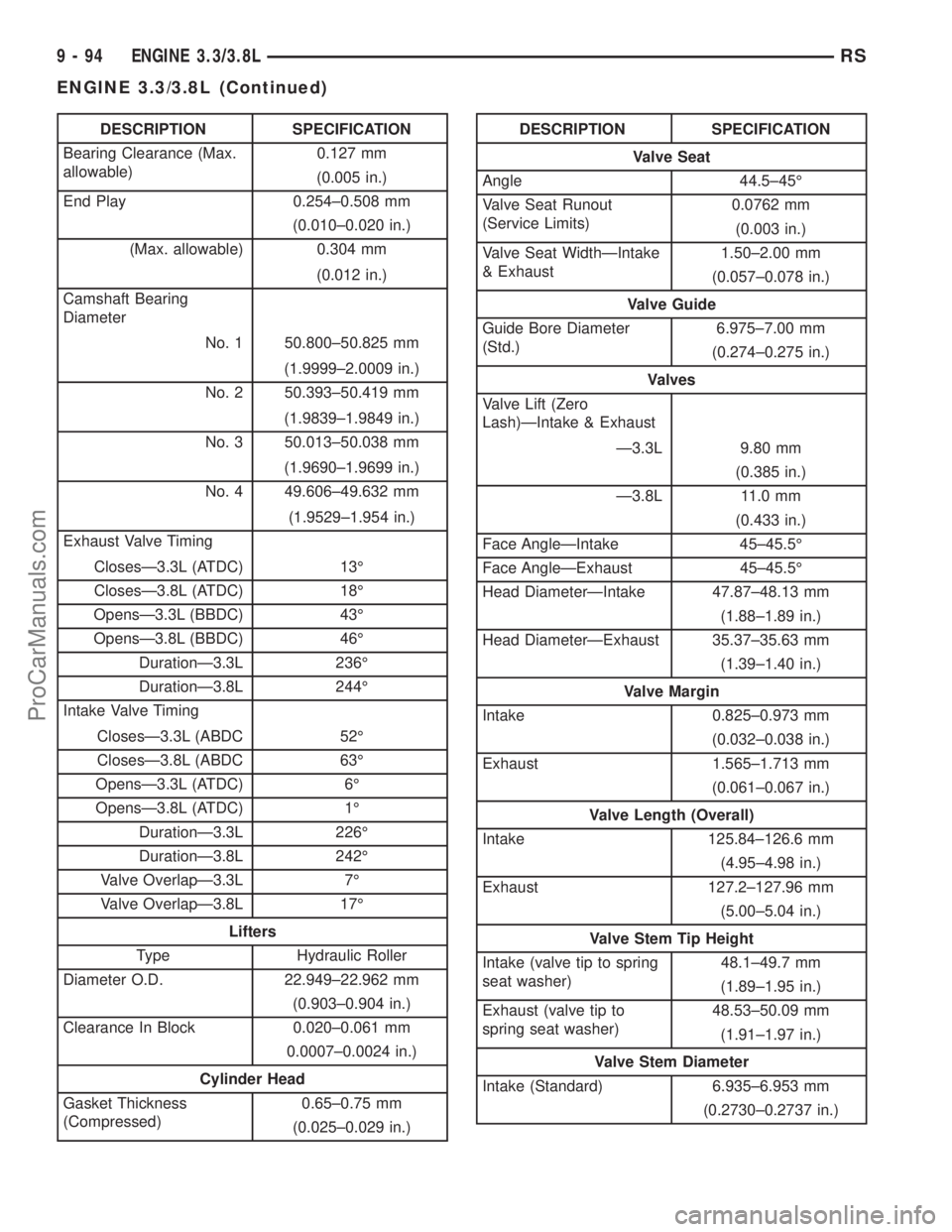
DESCRIPTION SPECIFICATION
Bearing Clearance (Max.
allowable)0.127 mm
(0.005 in.)
End Play 0.254±0.508 mm
(0.010±0.020 in.)
(Max. allowable) 0.304 mm
(0.012 in.)
Camshaft Bearing
Diameter
No. 1 50.800±50.825 mm
(1.9999±2.0009 in.)
No. 2 50.393±50.419 mm
(1.9839±1.9849 in.)
No. 3 50.013±50.038 mm
(1.9690±1.9699 in.)
No. 4 49.606±49.632 mm
(1.9529±1.954 in.)
Exhaust Valve Timing
ClosesÐ3.3L (ATDC) 13É
ClosesÐ3.8L (ATDC) 18É
OpensÐ3.3L (BBDC) 43É
OpensÐ3.8L (BBDC) 46É
DurationÐ3.3L 236É
DurationÐ3.8L 244É
Intake Valve Timing
ClosesÐ3.3L (ABDC 52É
ClosesÐ3.8L (ABDC 63É
OpensÐ3.3L (ATDC) 6É
OpensÐ3.8L (ATDC) 1É
DurationÐ3.3L 226É
DurationÐ3.8L 242É
Valve OverlapÐ3.3L 7É
Valve OverlapÐ3.8L 17É
Lifters
Type Hydraulic Roller
Diameter O.D. 22.949±22.962 mm
(0.903±0.904 in.)
Clearance In Block 0.020±0.061 mm
0.0007±0.0024 in.)
Cylinder Head
Gasket Thickness
(Compressed)0.65±0.75 mm
(0.025±0.029 in.)DESCRIPTION SPECIFICATION
Valve Seat
Angle 44.5±45É
Valve Seat Runout
(Service Limits)0.0762 mm
(0.003 in.)
Valve Seat WidthÐIntake
& Exhaust1.50±2.00 mm
(0.057±0.078 in.)
Valve Guide
Guide Bore Diameter
(Std.)6.975±7.00 mm
(0.274±0.275 in.)
Valves
Valve Lift (Zero
Lash)ÐIntake & Exhaust
Ð3.3L 9.80 mm
(0.385 in.)
Ð3.8L 11.0 mm
(0.433 in.)
Face AngleÐIntake 45±45.5É
Face AngleÐExhaust 45±45.5É
Head DiameterÐIntake 47.87±48.13 mm
(1.88±1.89 in.)
Head DiameterÐExhaust 35.37±35.63 mm
(1.39±1.40 in.)
Valve Margin
Intake 0.825±0.973 mm
(0.032±0.038 in.)
Exhaust 1.565±1.713 mm
(0.061±0.067 in.)
Valve Length (Overall)
Intake 125.84±126.6 mm
(4.95±4.98 in.)
Exhaust 127.2±127.96 mm
(5.00±5.04 in.)
Valve Stem Tip Height
Intake (valve tip to spring
seat washer)48.1±49.7 mm
(1.89±1.95 in.)
Exhaust (valve tip to
spring seat washer)48.53±50.09 mm
(1.91±1.97 in.)
Valve Stem Diameter
Intake (Standard) 6.935±6.953 mm
(0.2730±0.2737 in.)
9 - 94 ENGINE 3.3/3.8LRS
ENGINE 3.3/3.8L (Continued)
ProCarManuals.com
Page 1297 of 2399
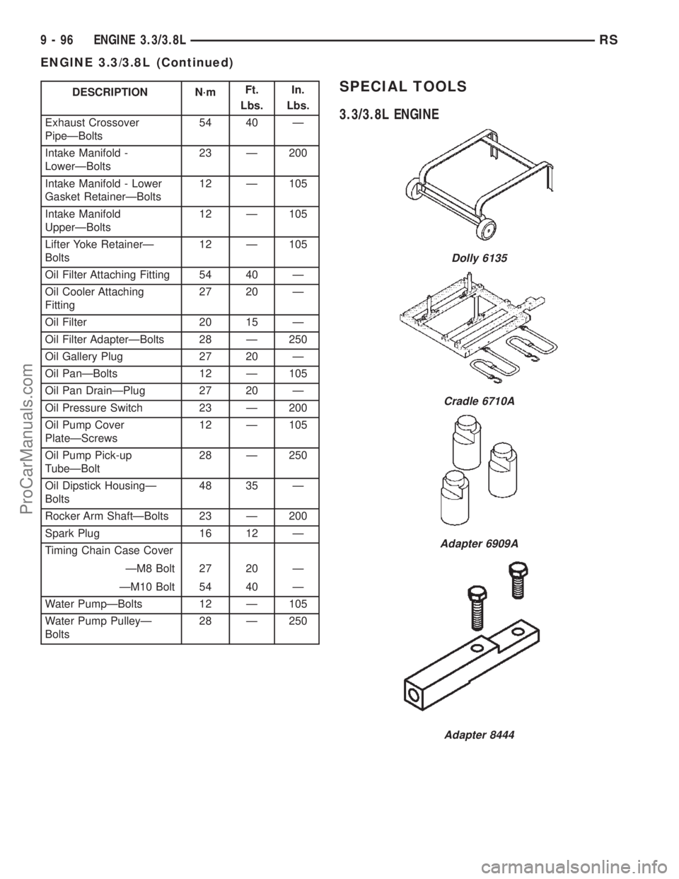
DESCRIPTION N´mFt.
Lbs.In.
Lbs.
Exhaust Crossover
PipeÐBolts54 40 Ð
Intake Manifold -
LowerÐBolts23 Ð 200
Intake Manifold - Lower
Gasket RetainerÐBolts12 Ð 105
Intake Manifold
UpperÐBolts12 Ð 105
Lifter Yoke RetainerÐ
Bolts12 Ð 105
Oil Filter Attaching Fitting 54 40 Ð
Oil Cooler Attaching
Fitting27 20 Ð
Oil Filter 20 15 Ð
Oil Filter AdapterÐBolts 28 Ð 250
Oil Gallery Plug 27 20 Ð
Oil PanÐBolts 12 Ð 105
Oil Pan DrainÐPlug 27 20 Ð
Oil Pressure Switch 23 Ð 200
Oil Pump Cover
PlateÐScrews12 Ð 105
Oil Pump Pick-up
TubeÐBolt28 Ð 250
Oil Dipstick HousingÐ
Bolts48 35 Ð
Rocker Arm ShaftÐBolts 23 Ð 200
Spark Plug 16 12 Ð
Timing Chain Case Cover
ÐM8 Bolt 27 20 Ð
ÐM10 Bolt 54 40 Ð
Water PumpÐBolts 12 Ð 105
Water Pump PulleyÐ
Bolts28 Ð 250SPECIAL TOOLS
3.3/3.8L ENGINE
Dolly 6135
Cradle 6710A
Adapter 6909A
Adapter 8444
9 - 96 ENGINE 3.3/3.8LRS
ENGINE 3.3/3.8L (Continued)
ProCarManuals.com
Page 1315 of 2399
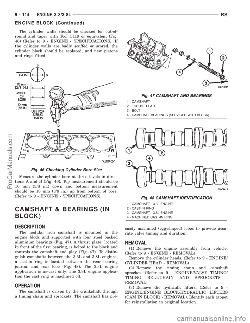
The cylinder walls should be checked for out-of-
round and taper with Tool C119 or equivalent (Fig.
46) (Refer to 9 - ENGINE - SPECIFICATIONS). If
the cylinder walls are badly scuffed or scored, the
cylinder block should be replaced, and new pistons
and rings fitted.
Measure the cylinder bore at three levels in direc-
tions A and B (Fig. 46). Top measurement should be
10 mm (3/8 in.) down and bottom measurement
should be 10 mm (3/8 in.) up from bottom of bore.
(Refer to 9 - ENGINE - SPECIFICATIONS).
CAMSHAFT & BEARINGS (IN
BLOCK)
DESCRIPTION
The nodular iron camshaft is mounted in the
engine block and supported with four steel backed
aluminum bearings (Fig. 47). A thrust plate, located
in front of the first bearing, is bolted to the block and
controls the camshaft end play (Fig. 47). To distin-
guish camshafts between the 3.3L and 3.8L engines,
a cast-in ring is located between the rear bearing
journal and rear lobe (Fig. 48). The 3.3L engine
application is as-cast only. The 3.8L engine applica-
tion the cast ring is machined off.
OPERATION
The camshaft is driven by the crankshaft through
a timing chain and sprockets. The camshaft has pre-cisely machined (egg-shaped) lobes to provide accu-
rate valve timing and duration.
REMOVAL
(1) Remove the engine assembly from vehicle.
(Refer to 9 - ENGINE - REMOVAL)
Remove the cylinder heads. (Refer to 9 - ENGINE/
CYLINDER HEAD - REMOVAL)
(2) Remove the timing chain and camshaft
sprocket. (Refer to 9 - ENGINE/VALVE TIMING/
TIMING BELT/CHAIN AND SPROCKETS -
REMOVAL)
(3) Remove the hydraulic lifters. (Refer to 9 -
ENGINE/ENGINE BLOCK/HYDRAULIC LIFTERS
(CAM IN BLOCK) - REMOVAL). Identify each tappet
for reinstallation in original location.
Fig. 46 Checking Cylinder Bore Size
Fig. 47 CAMSHAFT AND BEARINGS
1 - CAMSHAFT
2 - THRUST PLATE
3 - BOLT
4 - CAMSHAFT BEARINGS (SERVICED WITH BLOCK)
Fig. 48 CAMSHAFT IDENTIFICATION
1 - CAMSHAFT - 3.3L ENGINE
2 - CAST-IN RING
3 - CAMSHAFT - 3.8L ENGINE
4 - MACHINED CAST-IN RING
9 - 114 ENGINE 3.3/3.8LRS
ENGINE BLOCK (Continued)
ProCarManuals.com
Page 1316 of 2399
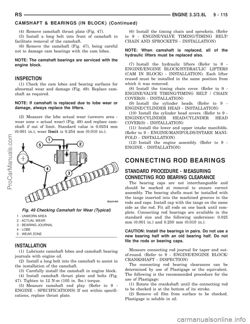
(4) Remove camshaft thrust plate (Fig. 47).
(5) Install a long bolt into front of camshaft to
facilitate removal of the camshaft.
(6) Remove the camshaft (Fig. 47), being careful
not to damage cam bearings with the cam lobes.
NOTE: The camshaft bearings are serviced with the
engine block.
INSPECTION
(1) Check the cam lobes and bearing surfaces for
abnormal wear and damage (Fig. 49). Replace cam-
shaft as required.
NOTE: If camshaft is replaced due to lobe wear or
damage, always replace the lifters.
(2) Measure the lobe actual wear (unworn area -
wear zone = actual wear) (Fig. 49) and replace cam-
shaft if out of limit. Standard value is 0.0254 mm
(0.001 in.), wearlimitis 0.254 mm (0.010 in.).
INSTALLATION
(1) Lubricate camshaft lobes and camshaft bearing
journals with engine oil.
(2) Install a long bolt into the camshaft to assist in
the installation of the camshaft.
(3) Carefully install the camshaft in engine block.
(4) Install camshaft thrust plate and bolts (Fig.
47). Tighten to 12 N´m (105 in. lbs.) torque.
(5) Measure camshaft end play. (Refer to 9 -
ENGINE - SPECIFICATIONS) If not within specifi-
cations, replace thrust plate.(6) Install the timing chain and sprockets. (Refer
to 9 - ENGINE/VALVE TIMING/TIMING BELT/
CHAIN AND SPROCKETS - INSTALLATION)
NOTE: When camshaft is replaced, all of the
hydraulic lifters must be replaced also.
(7) Install the hydraulic lifters (Refer to 9 -
ENGINE/ENGINE BLOCK/HYDRAULIC LIFTERS
(CAM IN BLOCK) - INSTALLATION). Each lifter
reused must be installed in the same position from
which it was removed.
(8) Install the timing chain cover. (Refer to 9 -
ENGINE/VALVE TIMING/TIMING BELT / CHAIN
COVER(S) - INSTALLATION)
(9) Install the cylinder heads. (Refer to 9 -
ENGINE/CYLINDER HEAD - INSTALLATION)
(10) Install the cylinder head covers. (Refer to 9 -
ENGINE/CYLINDER HEAD/CYLINDER HEAD
COVER(S) - INSTALLATION)
(11) Install the lower and upper intake manifolds.
(Refer to 9 - ENGINE/MANIFOLDS/INTAKE MANI-
FOLD - INSTALLATION)
(12) Install the engine assembly. (Refer to 9 -
ENGINE - INSTALLATION)
CONNECTING ROD BEARINGS
STANDARD PROCEDURE - MEASURING
CONNECTING ROD BEARING CLEARANCE
The bearing caps are not interchangeable and
should be marked at removal to ensure correct
assembly. The bearing shells must be installed with
the tangs inserted into the machined grooves in the
rods and caps. Install cap with the tangs on the same
side as the rod. Fit all rods on one bank until com-
plete. Connecting rod bearings are available in the
standard size and the following undersizes: 0.025
mm (0.001 in.) and 0.250 mm (0.010 in.).
CAUTION: Install the bearings in pairs. Do not use a
new bearing half with an old bearing half. Do not
file the rods or bearing caps.
Measure connecting rod journal for taper and out-
of-round. (Refer to 9 - ENGINE/ENGINE BLOCK/
CRANKSHAFT - INSPECTION)
The connecting rod bearing clearances can be
determined by use of Plastigage or the equivalent.
The following is the recommended procedure for the
use of Plastigage:
(1) Rotate the crankshaft until the connecting rod
to be checked is at the bottom of its stroke.
(2) Remove oil film from surface to be checked.
Plastigage is soluble in oil.
Fig. 49 Checking Camshaft for Wear (Typical)
1 - UNWORN AREA
2 - ACTUAL WEAR
3 - BEARING JOURNAL
4 - LOBE
5 - WEAR ZONE
RSENGINE 3.3/3.8L9 - 115
CAMSHAFT & BEARINGS (IN BLOCK) (Continued)
ProCarManuals.com
Page 1318 of 2399
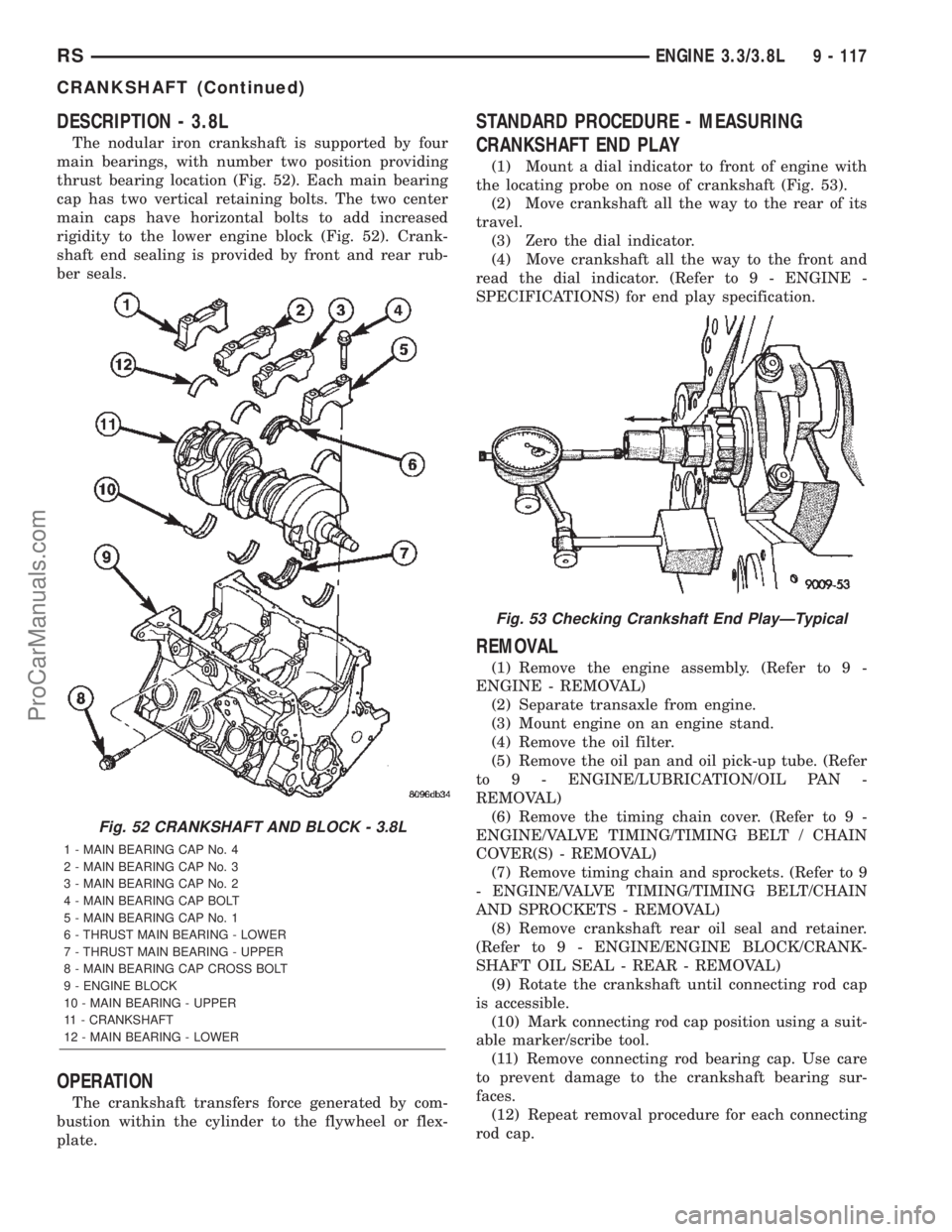
DESCRIPTION - 3.8L
The nodular iron crankshaft is supported by four
main bearings, with number two position providing
thrust bearing location (Fig. 52). Each main bearing
cap has two vertical retaining bolts. The two center
main caps have horizontal bolts to add increased
rigidity to the lower engine block (Fig. 52). Crank-
shaft end sealing is provided by front and rear rub-
ber seals.
OPERATION
The crankshaft transfers force generated by com-
bustion within the cylinder to the flywheel or flex-
plate.
STANDARD PROCEDURE - MEASURING
CRANKSHAFT END PLAY
(1) Mount a dial indicator to front of engine with
the locating probe on nose of crankshaft (Fig. 53).
(2) Move crankshaft all the way to the rear of its
travel.
(3) Zero the dial indicator.
(4) Move crankshaft all the way to the front and
read the dial indicator. (Refer to 9 - ENGINE -
SPECIFICATIONS) for end play specification.
REMOVAL
(1) Remove the engine assembly. (Refer to 9 -
ENGINE - REMOVAL)
(2) Separate transaxle from engine.
(3) Mount engine on an engine stand.
(4) Remove the oil filter.
(5) Remove the oil pan and oil pick-up tube. (Refer
to 9 - ENGINE/LUBRICATION/OIL PAN -
REMOVAL)
(6) Remove the timing chain cover. (Refer to 9 -
ENGINE/VALVE TIMING/TIMING BELT / CHAIN
COVER(S) - REMOVAL)
(7) Remove timing chain and sprockets. (Refer to 9
- ENGINE/VALVE TIMING/TIMING BELT/CHAIN
AND SPROCKETS - REMOVAL)
(8) Remove crankshaft rear oil seal and retainer.
(Refer to 9 - ENGINE/ENGINE BLOCK/CRANK-
SHAFT OIL SEAL - REAR - REMOVAL)
(9) Rotate the crankshaft until connecting rod cap
is accessible.
(10) Mark connecting rod cap position using a suit-
able marker/scribe tool.
(11) Remove connecting rod bearing cap. Use care
to prevent damage to the crankshaft bearing sur-
faces.
(12) Repeat removal procedure for each connecting
rod cap.
Fig. 52 CRANKSHAFT AND BLOCK - 3.8L
1 - MAIN BEARING CAP No. 4
2 - MAIN BEARING CAP No. 3
3 - MAIN BEARING CAP No. 2
4 - MAIN BEARING CAP BOLT
5 - MAIN BEARING CAP No. 1
6 - THRUST MAIN BEARING - LOWER
7 - THRUST MAIN BEARING - UPPER
8 - MAIN BEARING CAP CROSS BOLT
9 - ENGINE BLOCK
10 - MAIN BEARING - UPPER
11 - CRANKSHAFT
12 - MAIN BEARING - LOWER
Fig. 53 Checking Crankshaft End PlayÐTypical
RSENGINE 3.3/3.8L9 - 117
CRANKSHAFT (Continued)
ProCarManuals.com
Page 1319 of 2399
(13) Remove and discard the main bearing cross
bolts and washers (3.8L engine only).
NOTE: Install new cross bolt and washer assembly
(3.8L engine only) upon reassembly.
(14) Remove the main bearing cap bolts
(15) Remove the main bearing caps.
(16) Remove the crankshaft from engine block.
INSPECTION
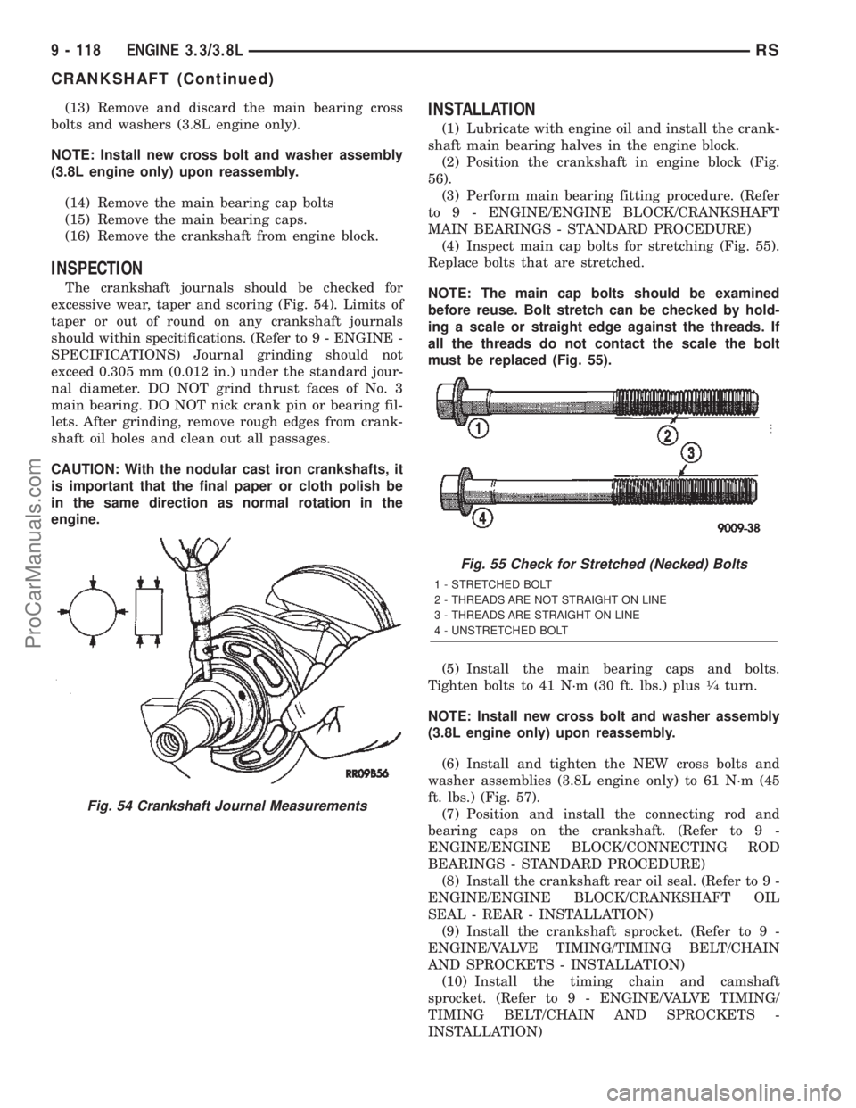
The crankshaft journals should be checked for
excessive wear, taper and scoring (Fig. 54). Limits of
taper or out of round on any crankshaft journals
should within specitifications. (Refer to 9 - ENGINE -
SPECIFICATIONS) Journal grinding should not
exceed 0.305 mm (0.012 in.) under the standard jour-
nal diameter. DO NOT grind thrust faces of No. 3
main bearing. DO NOT nick crank pin or bearing fil-
lets. After grinding, remove rough edges from crank-
shaft oil holes and clean out all passages.
CAUTION: With the nodular cast iron crankshafts, it
is important that the final paper or cloth polish be
in the same direction as normal rotation in the
engine.
INSTALLATION
(1) Lubricate with engine oil and install the crank-
shaft main bearing halves in the engine block.
(2) Position the crankshaft in engine block (Fig.
56).
(3) Perform main bearing fitting procedure. (Refer
to 9 - ENGINE/ENGINE BLOCK/CRANKSHAFT
MAIN BEARINGS - STANDARD PROCEDURE)
(4) Inspect main cap bolts for stretching (Fig. 55).
Replace bolts that are stretched.
NOTE: The main cap bolts should be examined
before reuse. Bolt stretch can be checked by hold-
ing a scale or straight edge against the threads. If
all the threads do not contact the scale the bolt
must be replaced (Fig. 55).
(5) Install the main bearing caps and bolts.
Tighten bolts to 41 N´m (30 ft. lbs.) plus
1¤4turn.
NOTE: Install new cross bolt and washer assembly
(3.8L engine only) upon reassembly.
(6) Install and tighten the NEW cross bolts and
washer assemblies (3.8L engine only) to 61 N´m (45
ft. lbs.) (Fig. 57).
(7) Position and install the connecting rod and
bearing caps on the crankshaft. (Refer to 9 -
ENGINE/ENGINE BLOCK/CONNECTING ROD
BEARINGS - STANDARD PROCEDURE)
(8) Install the crankshaft rear oil seal. (Refer to 9 -
ENGINE/ENGINE BLOCK/CRANKSHAFT OIL
SEAL - REAR - INSTALLATION)
(9) Install the crankshaft sprocket. (Refer to 9 -
ENGINE/VALVE TIMING/TIMING BELT/CHAIN
AND SPROCKETS - INSTALLATION)
(10) Install the timing chain and camshaft
sprocket. (Refer to 9 - ENGINE/VALVE TIMING/
TIMING BELT/CHAIN AND SPROCKETS -
INSTALLATION)
Fig. 54 Crankshaft Journal Measurements
Fig. 55 Check for Stretched (Necked) Bolts
1 - STRETCHED BOLT
2 - THREADS ARE NOT STRAIGHT ON LINE
3 - THREADS ARE STRAIGHT ON LINE
4 - UNSTRETCHED BOLT
9 - 118 ENGINE 3.3/3.8LRS
CRANKSHAFT (Continued)
ProCarManuals.com