2002 CHRYSLER TOWN AND COUNTRY index
[x] Cancel search: indexPage 2130 of 2399
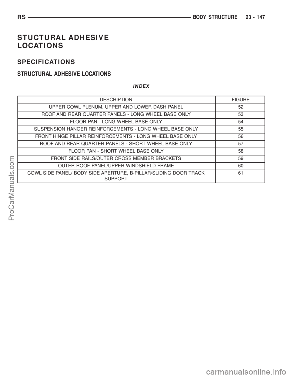
STUCTURAL ADHESIVE
LOCATIONS
SPECIFICATIONS
STRUCTURAL ADHESIVE LOCATIONS
INDEX
DESCRIPTION FIGURE
UPPER COWL PLENUM, UPPER AND LOWER DASH PANEL 52
ROOF AND REAR QUARTER PANELS - LONG WHEEL BASE ONLY 53
FLOOR PAN - LONG WHEEL BASE ONLY 54
SUSPENSION HANGER REINFORCEMENTS - LONG WHEEL BASE ONLY 55
FRONT HINGE PILLAR REINFORCEMENTS - LONG WHEEL BASE ONLY 56
ROOF AND REAR QUARTER PANELS - SHORT WHEEL BASE ONLY 57
FLOOR PAN - SHORT WHEEL BASE ONLY 58
FRONT SIDE RAILS/OUTER CROSS MEMBER BRACKETS 59
OUTER ROOF PANEL/UPPER WINDSHIELD FRAME 60
COWL SIDE PANEL/ BODY SIDE APERTURE, B-PILLAR/SLIDING DOOR TRACK
SUPPORT61
RSBODY STRUCTURE23 - 147
ProCarManuals.com
Page 2139 of 2399
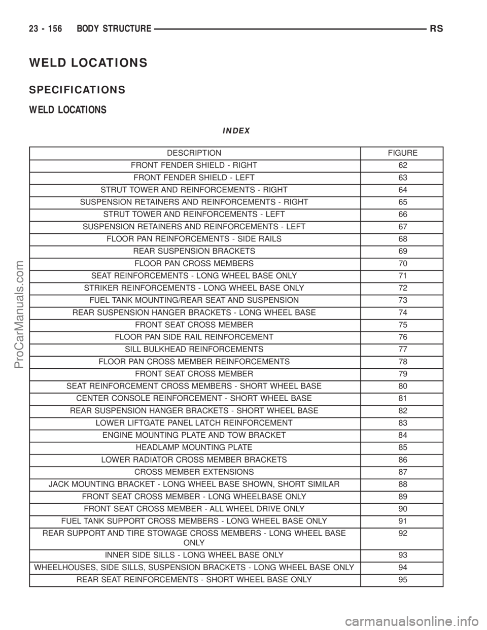
WELD LOCATIONS
SPECIFICATIONS
WELD LOCATIONS
INDEX
DESCRIPTION FIGURE
FRONT FENDER SHIELD - RIGHT 62
FRONT FENDER SHIELD - LEFT 63
STRUT TOWER AND REINFORCEMENTS - RIGHT 64
SUSPENSION RETAINERS AND REINFORCEMENTS - RIGHT 65
STRUT TOWER AND REINFORCEMENTS - LEFT 66
SUSPENSION RETAINERS AND REINFORCEMENTS - LEFT 67
FLOOR PAN REINFORCEMENTS - SIDE RAILS 68
REAR SUSPENSION BRACKETS 69
FLOOR PAN CROSS MEMBERS 70
SEAT REINFORCEMENTS - LONG WHEEL BASE ONLY 71
STRIKER REINFORCEMENTS - LONG WHEEL BASE ONLY 72
FUEL TANK MOUNTING/REAR SEAT AND SUSPENSION 73
REAR SUSPENSION HANGER BRACKETS - LONG WHEEL BASE 74
FRONT SEAT CROSS MEMBER 75
FLOOR PAN SIDE RAIL REINFORCEMENT 76
SILL BULKHEAD REINFORCEMENTS 77
FLOOR PAN CROSS MEMBER REINFORCEMENTS 78
FRONT SEAT CROSS MEMBER 79
SEAT REINFORCEMENT CROSS MEMBERS - SHORT WHEEL BASE 80
CENTER CONSOLE REINFORCEMENT - SHORT WHEEL BASE 81
REAR SUSPENSION HANGER BRACKETS - SHORT WHEEL BASE 82
LOWER LIFTGATE PANEL LATCH REINFORCEMENT 83
ENGINE MOUNTING PLATE AND TOW BRACKET 84
HEADLAMP MOUNTING PLATE 85
LOWER RADIATOR CROSS MEMBER BRACKETS 86
CROSS MEMBER EXTENSIONS 87
JACK MOUNTING BRACKET - LONG WHEEL BASE SHOWN, SHORT SIMILAR 88
FRONT SEAT CROSS MEMBER - LONG WHEELBASE ONLY 89
FRONT SEAT CROSS MEMBER - ALL WHEEL DRIVE ONLY 90
FUEL TANK SUPPORT CROSS MEMBERS - LONG WHEEL BASE ONLY 91
REAR SUPPORT AND TIRE STOWAGE CROSS MEMBERS - LONG WHEEL BASE
ONLY92
INNER SIDE SILLS - LONG WHEEL BASE ONLY 93
WHEELHOUSES, SIDE SILLS, SUSPENSION BRACKETS - LONG WHEEL BASE ONLY 94
REAR SEAT REINFORCEMENTS - SHORT WHEEL BASE ONLY 95
23 - 156 BODY STRUCTURERS
ProCarManuals.com
Page 2254 of 2399
REMOVAL
(1) Disconnect and isolate the battery negative
cable.
(2) Disconnect the headlamp and dash wire har-
ness connector for the A/C pressure transducer from
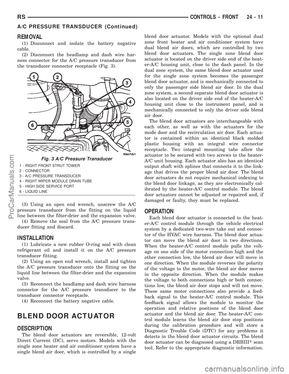
the transducer connector receptacle (Fig. 3).
(3) Using an open end wrench, unscrew the A/C
pressure transducer from the fitting on the liquid
line between the filter-drier and the expansion valve.
(4) Remove the seal from the A/C pressure trans-
ducer fitting and discard.
INSTALLATION
(1) Lubricate a new rubber O-ring seal with clean
refrigerant oil and install it on the A/C pressure
transducer fitting.
(2) Using an open end wrench, install and tighten
the A/C pressure transducer onto the fitting on the
liquid line between the filter-drier and the expansion
valve.
(3) Reconnect the headlamp and dash wire harness
connector for the A/C pressure transducer to the
transducer connector receptacle.
(4) Reconnect the battery negative cable.
BLEND DOOR ACTUATOR
DESCRIPTION
The blend door actuators are reversible, 12-volt
Direct Current (DC), servo motors. Models with the
single zone heater and air conditioner system have a
single blend air door, which is controlled by a singleblend door actuator. Models with the optional dual
zone front heater and air conditioner system have
dual blend air doors, which are controlled by two
blend door actuators. The single zone blend door
actuator is located on the driver side end of the heat-
er-A/C housing unit, close to the dash panel. In the
dual zone system, the same blend door actuator used
for the single zone system becomes the passenger
blend door actuator, and is mechanically connected to
only the passenger side blend air door. In the dual
zone system, a second separate blend door actuator is
also located on the driver side end of the heater-A/C
housing unit close to the instrument panel, and is
mechanically connected to only the driver side blend
air door.
The blend door actuators are interchangeable with
each other, as well as with the actuators for the
mode door and the recirculation air door. Each actua-
tor is contained within an identical black molded
plastic housing with an integral wire connector
receptacle. Two integral mounting tabs allow the
actuator to be secured with two screws to the heater-
A/C unit housing. Each actuator also has an identical
output shaft with splines that connects it to the link-
age that drives the proper blend air door. The blend
door actuators do not require mechanical indexing to
the blend door linkage, as they are electronically cal-
ibrated by the heater-A/C control module. The blend
door actuators cannot be adjusted or repaired and, if
damaged or faulty, they must be replaced.
OPERATION
Each blend door actuator is connected to the heat-
er-A/C control module through the vehicle electrical
system by a dedicated two-wire take out and connec-
tor of the HVAC wire harness. The blend door actua-
tor can move the blend air door in two directions.
When the heater-A/C control module pulls the volt-
age on one side of the motor connection high and the
other connection low, the blend air door will move in
one direction. When the module reverses the polarity
of the voltage to the motor, the blend air door moves
in the opposite direction. When the module makes
the voltage to both connections high or both connec-
tions low, the blend air door stops and will not move.
These same motor connections also provide a feed-
back signal to the heater-A/C control module. This
feedback signal allows the module to monitor the
operation and relative positions of the blend door
actuator and the blend air door. The heater-A/C con-
trol module learns the blend air door stop positions
during the calibration procedure and will store a
Diagnostic Trouble Code (DTC) for any problems it
detects in the blend door actuator circuits. The blend
door actuator can be diagnosed using a DRBIIItscan
tool. Refer to the appropriate diagnostic information.
Fig. 3 A/C Pressure Transducer
1 - RIGHT FRONT STRUT TOWER
2 - CONNECTOR
3 - A/C PRESSURE TRANSDUCER
4 - RIGHT WIPER MODULE DRAIN TUBE
5 - HIGH SIDE SERVICE PORT
6 - LIQUID LINE
RSCONTROLS - FRONT24-11
A/C PRESSURE TRANSDUCER (Continued)
ProCarManuals.com
Page 2268 of 2399
it to the linkage that drives the mode door. The mode
door actuator does not require mechanical indexing
to the mode door linkage, as it is electronically cali-
brated by the heater-A/C control module. The mode
door actuator cannot be adjusted or repaired and, if
damaged or faulty, it must be replaced.
OPERATION
The mode door actuator is connected to the heater-
A/C control module through the vehicle electrical sys-
tem by a dedicated two-wire take out and connector
of the HVAC wire harness. The mode door actuator
can move the mode door in two directions. When the
heater-A/C control module pulls the voltage on one
side of the motor connection high and the other con-
nection low, the mode door will move in one direction.
When the module reverses the polarity of the voltage
to the motor, the mode door moves in the opposite
direction. When the module makes the voltage to
both connections high or both connections low, the
mode door stops and will not move. These same
motor connections also provide a feedback signal to
the heater-A/C control module. This feedback signal
allows the module to monitor the operation and rela-
tive position of the mode door actuator and the mode
door. The heater-A/C control module learns the mode
door stop positions during the calibration procedure
and will store a Diagnostic Trouble Code (DTC) for
any problems it detects in the mode door actuator
circuits. The mode door actuator can be diagnosed
using a DRBIIItscan tool. Refer to the appropriate
diagnostic information.
REMOVAL
WARNING: ON VEHICLES EQUIPPED WITH AIR-
BAGS, DISABLE THE AIRBAG SYSTEM BEFORE
ATTEMPTING ANY STEERING WHEEL, STEERING
COLUMN, OR INSTRUMENT PANEL COMPONENT
DIAGNOSIS OR SERVICE. DISCONNECT AND ISO-
LATE THE BATTERY NEGATIVE (GROUND) CABLE,
THEN WAIT TWO MINUTES FOR THE AIRBAG SYS-
TEM CAPACITOR TO DISCHARGE BEFORE PER-
FORMING FURTHER DIAGNOSIS OR SERVICE. THIS
IS THE ONLY SURE WAY TO DISABLE THE AIRBAG
SYSTEM. FAILURE TO TAKE THE PROPER PRE-
CAUTIONS COULD RESULT IN ACCIDENTAL AIR-
BAG DEPLOYMENT AND POSSIBLE PERSONAL
INJURY.
(1) Disconnect and isolate the battery negative
cable.
(2) Remove the silencer from beneath the driver
side end of the instrument panel. (Refer to 23 -
BODY/INSTRUMENT PANEL/INSTRUMENT
PANEL SILENCER - REMOVAL).(3) Disconnect the HVAC wire harness connector
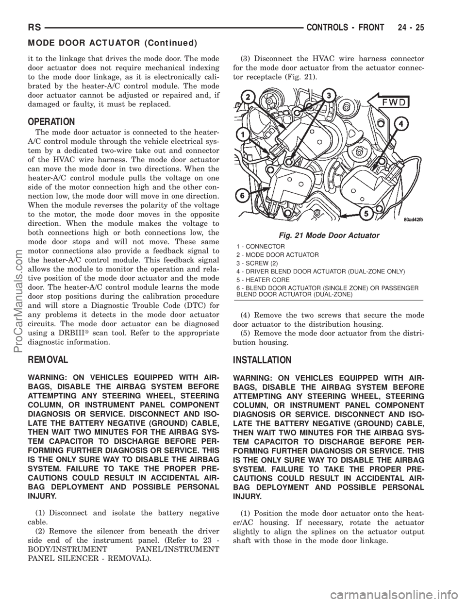
for the mode door actuator from the actuator connec-
tor receptacle (Fig. 21).
(4) Remove the two screws that secure the mode
door actuator to the distribution housing.
(5) Remove the mode door actuator from the distri-
bution housing.
INSTALLATION
WARNING: ON VEHICLES EQUIPPED WITH AIR-
BAGS, DISABLE THE AIRBAG SYSTEM BEFORE
ATTEMPTING ANY STEERING WHEEL, STEERING
COLUMN, OR INSTRUMENT PANEL COMPONENT
DIAGNOSIS OR SERVICE. DISCONNECT AND ISO-
LATE THE BATTERY NEGATIVE (GROUND) CABLE,
THEN WAIT TWO MINUTES FOR THE AIRBAG SYS-
TEM CAPACITOR TO DISCHARGE BEFORE PER-
FORMING FURTHER DIAGNOSIS OR SERVICE. THIS
IS THE ONLY SURE WAY TO DISABLE THE AIRBAG
SYSTEM. FAILURE TO TAKE THE PROPER PRE-
CAUTIONS COULD RESULT IN ACCIDENTAL AIR-
BAG DEPLOYMENT AND POSSIBLE PERSONAL
INJURY.
(1) Position the mode door actuator onto the heat-
er/AC housing. If necessary, rotate the actuator
slightly to align the splines on the actuator output
shaft with those in the mode door linkage.
Fig. 21 Mode Door Actuator
1 - CONNECTOR
2 - MODE DOOR ACTUATOR
3 - SCREW (2)
4 - DRIVER BLEND DOOR ACTUATOR (DUAL-ZONE ONLY)
5 - HEATER CORE
6 - BLEND DOOR ACTUATOR (SINGLE ZONE) OR PASSENGER
BLEND DOOR ACTUATOR (DUAL-ZONE)
RSCONTROLS - FRONT24-25
MODE DOOR ACTUATOR (Continued)
ProCarManuals.com
Page 2270 of 2399
connector for the power module from the module con-
nector receptacle.
(5) Reach through the glove box opening to access
and disconnect the blower motor pigtail wire connec-
tor from the power module connector receptacle.
(6) Remove the two screws that secure the power
module to the evaporator housing.
(7) Remove the power module from the evaporator
housing.
INSTALLATION
WARNING: ON VEHICLES EQUIPPED WITH AIR-
BAGS, DISABLE THE AIRBAG SYSTEM BEFORE
ATTEMPTING ANY STEERING WHEEL, STEERING
COLUMN, OR INSTRUMENT PANEL COMPONENT
DIAGNOSIS OR SERVICE. DISCONNECT AND ISO-
LATE THE BATTERY NEGATIVE (GROUND) CABLE,
THEN WAIT TWO MINUTES FOR THE AIRBAG SYS-
TEM CAPACITOR TO DISCHARGE BEFORE PER-
FORMING FURTHER DIAGNOSIS OR SERVICE. THIS
IS THE ONLY SURE WAY TO DISABLE THE AIRBAG
SYSTEM. FAILURE TO TAKE THE PROPER PRE-
CAUTIONS COULD RESULT IN ACCIDENTAL AIR-
BAG DEPLOYMENT AND POSSIBLE PERSONAL
INJURY.
(1) Position the power module into the evaporator
housing.
(2) Install and tighten the two screws that secure
the power module to the evaporator housing. Tighten
the screws to 2 N´m (18 in. lbs.).
(3) Reconnect the blower motor pigtail wire con-
nector to the power module connector receptacle.
(4) Reconnect the instrument panel wire harness
connector for the power module to the module con-
nector receptacle.
(5) Flex both sides of the glove box bin inward
near the top far enough for the rubber glove box stop
bumpers to clear the sides of the glove box opening,
then roll the glove box upward.
(6) Close and latch the glove box.
(7) Reconnect the battery negative cable.
RECIRCULATION DOOR
ACTUATOR
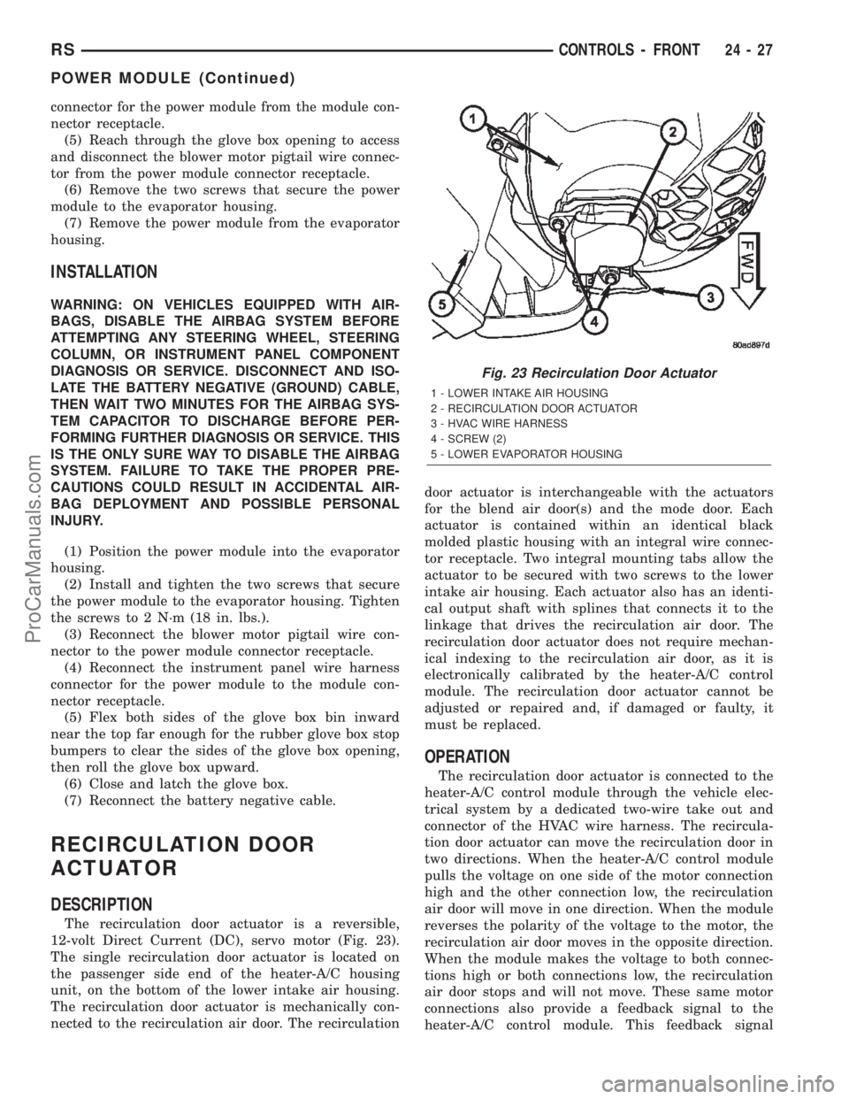
DESCRIPTION
The recirculation door actuator is a reversible,
12-volt Direct Current (DC), servo motor (Fig. 23).
The single recirculation door actuator is located on
the passenger side end of the heater-A/C housing
unit, on the bottom of the lower intake air housing.
The recirculation door actuator is mechanically con-
nected to the recirculation air door. The recirculationdoor actuator is interchangeable with the actuators
for the blend air door(s) and the mode door. Each
actuator is contained within an identical black
molded plastic housing with an integral wire connec-
tor receptacle. Two integral mounting tabs allow the
actuator to be secured with two screws to the lower
intake air housing. Each actuator also has an identi-
cal output shaft with splines that connects it to the
linkage that drives the recirculation air door. The
recirculation door actuator does not require mechan-
ical indexing to the recirculation air door, as it is
electronically calibrated by the heater-A/C control
module. The recirculation door actuator cannot be
adjusted or repaired and, if damaged or faulty, it
must be replaced.
OPERATION
The recirculation door actuator is connected to the
heater-A/C control module through the vehicle elec-
trical system by a dedicated two-wire take out and
connector of the HVAC wire harness. The recircula-
tion door actuator can move the recirculation door in
two directions. When the heater-A/C control module
pulls the voltage on one side of the motor connection
high and the other connection low, the recirculation
air door will move in one direction. When the module
reverses the polarity of the voltage to the motor, the
recirculation air door moves in the opposite direction.
When the module makes the voltage to both connec-
tions high or both connections low, the recirculation
air door stops and will not move. These same motor
connections also provide a feedback signal to the
heater-A/C control module. This feedback signal
Fig. 23 Recirculation Door Actuator
1 - LOWER INTAKE AIR HOUSING
2 - RECIRCULATION DOOR ACTUATOR
3 - HVAC WIRE HARNESS
4 - SCREW (2)
5 - LOWER EVAPORATOR HOUSING
RSCONTROLS - FRONT24-27
POWER MODULE (Continued)
ProCarManuals.com
Page 2273 of 2399
bezel with the snap clip receptacles on the retainer
above the headliner.
(7) Using hand pressure, press the top edge of the
rear heater-A/C control bezel upward until the two
snap clips are fully seated in their receptacles.
(8) Reconnect the battery negative cable.
(9) Using the DRB-IIItreset the Rear Tempera-
ture Selector calibration values.
(10) Verify that the Actuator Calibration of the
Front Control has passed. If an Actuator Calibration
has not passed correct any errors before proceeding
further.
(11) Rotate the Rear Temperature Selector counter
clockwise to the Cold Position, allow the Selector to
remain in the Cold Position for 5 seconds.
(12) Rotate the Rear Temperature Selector Clock-
wise to the Hot Position, allow the Selector to remain
in the Cold Position for 5 seconds.
(13) calibration is now complete.
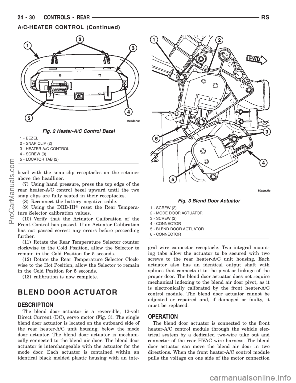
BLEND DOOR ACTUATOR
DESCRIPTION
The blend door actuator is a reversible, 12-volt
Direct Current (DC), servo motor (Fig. 3). The single
blend door actuator is located on the outboard side of
the rear heater-A/C unit housing, below the mode
door actuator. The blend door actuator is mechani-
cally connected to the blend air door. The blend door
actuator is interchangeable with the actuator for the
mode door. Each actuator is contained within an
identical black molded plastic housing with an inte-gral wire connector receptacle. Two integral mount-
ing tabs allow the actuator to be secured with two
screws to the rear heater-A/C unit housing. Each
actuator also has an identical output shaft with
splines that connects it to the pivot or linkage of the
proper door. The blend door actuator does not require
mechanical indexing to the blend air door pivot, as it
is electronically calibrated by the front heater-A/C
control module. The blend door actuator cannot be
adjusted or repaired and, if damaged or faulty, it
must be replaced.
OPERATION
The blend door actuator is connected to the front
heater-A/C control module through the vehicle elec-
trical system by a dedicated two-wire take out and
connector of the rear HVAC wire harness. The blend
door actuator can move the blend air door in two
directions. When the front heater-A/C control module
pulls the voltage on one side of the motor connection
Fig. 2 Heater-A/C Control Bezel
1 - BEZEL
2 - SNAP CLIP (2)
3 - HEATER-A/C CONTROL
4 - SCREW (3)
5 - LOCATOR TAB (2)
Fig. 3 Blend Door Actuator
1 - SCREW (2)
2 - MODE DOOR ACTUATOR
3 - SCREW (2)
4 - CONNECTOR
5 - BLEND DOOR ACTUATOR
6 - CONNECTOR
24 - 30 CONTROLS - REARRS
A/C-HEATER CONTROL (Continued)
ProCarManuals.com
Page 2319 of 2399
(11) Push both heater core tubes simultaneously
toward the dash panel far enough to disengage their
fittings from the heater core supply and return ports.
(12) Install plugs in, or tape over the opened
heater core tube fittings and both heater core ports.
(13) Use absorbent toweling to mop up any engine
coolant spills from the preceding operation.
(14) Remove the two screws that secure the heater
core mounting plate to the distribution housing.
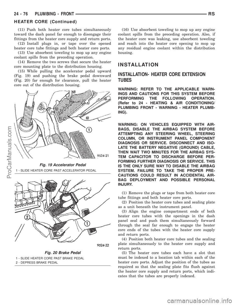
(15) While pulling the accelerator pedal upward
(Fig. 19) and pushing the brake pedal downward
(Fig. 20) far enough for clearance, pull the heater
core out of the distribution housing.(16) Use absorbent toweling to mop up any engine
coolant spills from the preceding operation. Also, if
the heater core was leaking, use absorbent toweling
and reach into the heater core opening to mop up
any residual engine coolant within the distribution
housing.
INSTALLATION
INSTALLATION- HEATER CORE EXTENSION
TUBES
WARNING: REFER TO THE APPLICABLE WARN-
INGS AND CAUTIONS FOR THIS SYSTEM BEFORE
PERFORMING THE FOLLOWING OPERATION.
(Refer to 24 - HEATING & AIR CONDITIONING/
PLUMBING FRONT - WARNING - HEATER PLUMB-
ING).
WARNING: ON VEHICLES EQUIPPED WITH AIR-
BAGS, DISABLE THE AIRBAG SYSTEM BEFORE
ATTEMPTING ANY STEERING WHEEL, STEERING
COLUMN, OR INSTRUMENT PANEL COMPONENT
DIAGNOSIS OR SERVICE. DISCONNECT AND ISO-
LATE THE BATTERY NEGATIVE (GROUND) CABLE,
THEN WAIT TWO MINUTES FOR THE AIRBAG SYS-
TEM CAPACITOR TO DISCHARGE BEFORE PER-
FORMING FURTHER DIAGNOSIS OR SERVICE. THIS
IS THE ONLY SURE WAY TO DISABLE THE AIRBAG
SYSTEM. FAILURE TO TAKE THE PROPER PRE-
CAUTIONS COULD RESULT IN ACCIDENTAL AIR-
BAG DEPLOYMENT AND POSSIBLE PERSONAL
INJURY.
(1) Remove the plugs or tape from both heater core
tube fittings and both heater core ports.
(2) Position the heater core tubes and sealing plate
as a unit beneath the instrument panel.
(3) Align the engine compartment ends of both
heater core tubes with the openings in the dash
panel seal and push them simultaneously forward
through the seal far enough to engage the heater
core ends of the tubes with the heater core supply
and return ports.
(4) Position both heater core tubes and the sealing
plate simultaneously to the heater core supply and
return ports.
(5) The heater core tubes each have a slot that
must be indexed to a location tab within each of the
heater core ports. Adjust the position of the tubes as
required so that the sealing plate fits flush against
the heater core supply and return ports, which indi-
cates that the tubes are properly indexed.
Fig. 19 Accelerator Pedal
1 - SLIDE HEATER CORE PAST ACCELERATOR PEDAL
Fig. 20 Brake Pedal
1 - SLIDE HEATER CORE PAST BRAKE PEDAL
2 - DEPRESS BRAKE PEDAL
24 - 76 PLUMBING - FRONTRS
HEATER CORE (Continued)
ProCarManuals.com
Page 2320 of 2399
(6) Install and tighten the screw that secures the
heater core tube sealing plate to the heater core sup-
ply and return ports. Tighten the screw to 3 N´m (27
in. lbs.).
(7) Position the heater core shield onto the distri-
bution housing. Be certain that the two location tabs
on the front of the shield are engaged in the recepta-
cles in the two lower finger formations of the evapo-
rator housing near the dash panel.
(8) Install and tighten the three screws that secure
the heater core shield to the left end of the HVAC
distribution housing. Tighten the screws to 2 N´m (17
in. lbs.).
(9) Reinstall the silencer under the driver side end
of the instrument panel. (Refer to 23 - BODY/IN-
STRUMENT PANEL/INSTRUMENT PANEL
SILENCER - INSTALLATION).
(10) Reconnect the heater hoses to the heater hose
tubes. (Refer to 24 - HEATING & AIR CONDITION-
ING/PLUMBING - FRONT/HEATER HOSE -
INSTALLATION).
(11) Reconnect the battery negative cable.
(12) Refill the engine cooling system. (Refer to 7 -
COOLING - STANDARD PROCEDURE - COOLING
SYSTEM REFILL).
INSTALLATION - HEATER CORE
WARNING: REFER TO THE APPLICABLE WARN-
INGS AND CAUTIONS FOR THIS SYSTEM BEFORE
PERFORMING THE FOLLOWING OPERATION.
(Refer to 24 - HEATING & AIR CONDITIONING/
PLUMBING FRONT - WARNING - HEATER PLUMB-
ING).
WARNING: ON VEHICLES EQUIPPED WITH AIR-
BAGS, DISABLE THE AIRBAG SYSTEM BEFORE
ATTEMPTING ANY STEERING WHEEL, STEERING
COLUMN, OR INSTRUMENT PANEL COMPONENT
DIAGNOSIS OR SERVICE. DISCONNECT AND ISO-
LATE THE BATTERY NEGATIVE (GROUND) CABLE,
THEN WAIT TWO MINUTES FOR THE AIRBAG SYS-
TEM CAPACITOR TO DISCHARGE BEFORE PER-
FORMING FURTHER DIAGNOSIS OR SERVICE. THIS
IS THE ONLY SURE WAY TO DISABLE THE AIRBAG
SYSTEM. FAILURE TO TAKE THE PROPER PRE-
CAUTIONS COULD RESULT IN ACCIDENTAL AIR-
BAG DEPLOYMENT AND POSSIBLE PERSONAL
INJURY.(1) While pushing the brake pedal downward and
pulling the accelerator pedal upward far enough for
clearance, slide the heater core into the distribution
housing.
(2) Install and tighten the two screws that secure
the heater core mounting plate to the distribution
housing. Tighten the screws to 2 N´m (17 in. lbs.).
(3) Remove the plugs or tape from the heater core
tube fittings and both heater core ports.
(4) Position both heater core tubes and the sealing
plate simultaneously to the heater core supply and
return ports.
(5) The heater core tubes each have a slot that
must be indexed to a location tab within each of the
heater core ports. Adjust the position of the tubes as
required so that the sealing plate fits flush against
the heater core supply and return ports, which indi-
cates that the tubes are properly indexed.
(6) Install and tighten the screw that secures the
heater core tube sealing plate to the heater core sup-
ply and return ports. Tighten the screw to 3 N´m (27
in. lbs.).
(7) Position the heater core shield onto the distri-
bution housing. Be certain that the two location tabs
on the front of the shield are engaged in the recepta-
cles in the two lower finger formations of the evapo-
rator housing near the dash panel.
(8) Install and tighten the three screws that secure
the heater core shield to the left end of the HVAC
distribution housing. Tighten the screws to 2 N´m (17
in. lbs.).
(9) Reconnect the power brake booster input rod
(push rod) to the pin on the brake pedal arm(Refer to
5 - BRAKES/HYDRAULIC/MECHANICAL/POWER
BRAKE BOOSTER - INSTALLATION).
(10) Reinstall the brake lamp switch into its
mounting bracket(Refer to 8 - ELECTRICAL/LAMPS/
LIGHTING - EXTERIOR/BRAKE LAMP SWITCH -
INSTALLATION).
(11) Reinstall the silencer boot around the base of
the lower steering shaft on the dash panel.
(12) Reconnect the battery negative cable.
(13) Refill the engine cooling system. (Refer to 7 -
COOLING - STANDARD PROCEDURE - COOLING
SYSTEM REFILL).
(14) Operate system for two thermostat cycles to
assure elimination of air in the system.
RSPLUMBING - FRONT24-77
HEATER CORE (Continued)
ProCarManuals.com