2002 CHRYSLER TOWN AND COUNTRY index
[x] Cancel search: indexPage 391 of 2399

(1) Turn the ignition switch to the Off position. Be
certain that all electrical accessories are turned off.
(2) Remove the nut with washer that secures the
battery hold down bracket to the battery tray and
support unit.
(3) Remove the battery hold down bracket from
the battery tray and support unit.
INSTALLATION
(1) Install the battery hold down bracket in the
battery tray and support unit.
(2) Install the nut with washer that secures the
battery hold down bracket to the battery tray and
support unit. Torque to 20 N´m (180 in. lbs.).
BATTERY CABLES
DESCRIPTION
The battery cables are large gauge, stranded cop-
per wires sheathed within a heavy plastic or syn-
thetic rubber insulating jacket. The wire used in the
battery cables combines excellent flexibility and reli-
ability with high electrical current carrying capacity.
Refer toWiring Diagramsin the index of this ser-
vice manual for the location of the proper battery
cable wire gauge information.
A clamping type female battery terminal made of
stamped metal is attached to one end of the battery
cable wire. A square headed pinch-bolt and hex nut
are installed at the open end of the female battery
terminal clamp. Large eyelet type terminals are
crimped onto the opposite end of the battery cable
wire and then solder-dipped. The battery positive
cable wires have a red insulating jacket to provide
visual identification and feature a larger female bat-
tery terminal clamp to allow connection to the larger
battery positive terminal post. The battery negative
cable wires have a black insulating jacket and a
smaller female battery terminal clamp.
The battery cables cannot be repaired and, if dam-
aged or faulty they must be replaced. Both the bat-
tery positive and negative cables are available for
service replacement only as a unit with the battery
wire harness, which may include portions of the wir-
ing circuits for the generator and other components
on some models. Refer toWiring Diagramsin the
index of this service manual for the location of more
information on the various wiring circuits included in
the battery wire harness for the vehicle being ser-
viced.
OPERATION
The battery cables connect the battery terminal
posts to the vehicle electrical system. These cables
also provide a path back to the battery for electricalcurrent generated by the charging system for restor-
ing the voltage potential of the battery. The female
battery terminal clamps on the ends of the battery
cable wires provide a strong and reliable connection
of the battery cable to the battery terminal posts.
The terminal pinch bolts allow the female terminal
clamps to be tightened around the male terminal
posts on the top of the battery. The eyelet terminals
secured to the opposite ends of the battery cable
wires from the female battery terminal clamps pro-
vide secure and reliable connection of the battery
cables to the vehicle electrical system.
The battery positive cable terminal clamp is
attached to the ends of two wires. One wire has an
eyelet terminal that connects the battery positive
cable to the B(+) terminal stud of the Integrated
Power Module (IPM), and the other wire has an eye-
let terminal that connects the battery positive cable
to the B(+) terminal stud of the engine starter motor
solenoid. The battery negative cable terminal clamp
is also attached to the ends of two wires. One wire
has an eyelet terminal that connects the battery neg-
ative cable to the vehicle powertrain through a stud
on the left side of the engine cylinder block. The
other wire has an eyelet terminal that connects the
battery negative cable to the vehicle body through a
ground screw on the left front fender inner shield,
near the battery.
DIAGNOSIS AND TESTING - BATTERY CABLE
A voltage drop test will determine if there is exces-
sive resistance in the battery cable terminal connec-
tions or the battery cable. If excessive resistance is
found in the battery cable connections, the connec-
tion point should be disassembled, cleaned of all cor-
rosion or foreign material, then reassembled.
Following reassembly, check the voltage drop for the
battery cable connection and the battery cable again
to confirm repair.
When performing the voltage drop test, it is impor-
tant to remember that the voltage drop is giving an
indication of the resistance between the two points at
which the voltmeter probes are attached.EXAM-
PLE:When testing the resistance of the battery pos-
itive cable, touch the voltmeter leads to the battery
positive cable terminal clamp and to the battery pos-
itive cable eyelet terminal at the starter solenoid
B(+) terminal stud. If you probe the battery positive
terminal post and the battery positive cable eyelet
terminal at the starter solenoid B(+) terminal stud,
you are reading the combined voltage drop in the
battery positive cable terminal clamp-to-terminal
post connection and the battery positive cable.
8F - 16 BATTERY SYSTEMRS
BATTERY HOLDDOWN (Continued)
ProCarManuals.com
Page 427 of 2399

battery movement during the most extreme vehicle
operation conditions. Periodic removal and lubrica-
tion of the battery holddown hardware is recom-
mended to prevent hardware seizure at a later date.
NOTE: Never operate a vehicle without a battery
holddown device properly installed. Damage to the
vehicle, components and battery could result.
REMOVAL
All of the battery hold down hardware can be ser-
viced without removal of the battery or the battery
tray and support unit.
(1) Turn the ignition switch to the Off position. Be
certain that all electrical accessories are turned off.
(2) Remove the nut with washer that secures the
battery hold down bracket to the battery tray and
support unit.
(3) Remove the battery hold down bracket from
the battery tray and support unit.
INSTALLATION
(1) Install the battery hold down bracket in the
battery tray and support unit.
(2) Install the nut with washer that secures the
battery hold down bracket to the battery tray and
support unit. Torque to 20 N´m (180 in. lbs.).
BATTERY CABLES
DESCRIPTION
The battery cables are large gauge, stranded cop-
per wires sheathed within a heavy plastic or syn-
thetic rubber insulating jacket. The wire used in the
battery cables combines excellent flexibility and reli-
ability with high electrical current carrying capacity.
Refer toWiring Diagramsin the index of this ser-
vice manual for the location of the proper battery
cable wire gauge information.
A clamping type female battery terminal made of
stamped metal is attached to one end of the battery
cable wire. A square headed pinch-bolt and hex nut
are installed at the open end of the female battery
terminal clamp. Large eyelet type terminals are
crimped onto the opposite end of the battery cable
wire and then solder-dipped. The battery positive
cable wires have a red insulating jacket to provide
visual identification and feature a larger female bat-
tery terminal clamp to allow connection to the larger
battery positive terminal post. The battery negative
cable wires have a black insulating jacket and a
smaller female battery terminal clamp.
The battery cables cannot be repaired and, if dam-
aged or faulty they must be replaced. Both the bat-
tery positive and negative cables are available forservice replacement only as a unit with the battery
wire harness, which may include portions of the wir-
ing circuits for the generator and other components
on some models. Refer toWiring Diagramsin the
index of this service manual for the location of more
information on the various wiring circuits included in
the battery wire harness for the vehicle being ser-
viced.
OPERATION
The battery cables connect the battery terminal
posts to the vehicle electrical system. These cables
also provide a path back to the battery for electrical
current generated by the charging system for restor-
ing the voltage potential of the battery. The female
battery terminal clamps on the ends of the battery
cable wires provide a strong and reliable connection
of the battery cable to the battery terminal posts.
The terminal pinch bolts allow the female terminal
clamps to be tightened around the male terminal
posts on the top of the battery. The eyelet terminals
secured to the opposite ends of the battery cable
wires from the female battery terminal clamps pro-
vide secure and reliable connection of the battery
cables to the vehicle electrical system.
The battery positive cable terminal clamp is
attached to the ends of two wires. One wire has an
eyelet terminal that connects the battery positive
cable to the B(+) terminal stud of the Integrated
Power Module (IPM), and the other wire has an eye-
let terminal that connects the battery positive cable
to the B(+) terminal stud of the engine starter motor
solenoid. The battery negative cable terminal clamp
is also attached to the ends of two wires. One wire
has an eyelet terminal that connects the battery neg-
ative cable to the vehicle powertrain through a stud
on the left side of the engine cylinder block. The
other wire has an eyelet terminal that connects the
battery negative cable to the vehicle body through a
ground screw on the left front fender inner shield,
near the battery.
DIAGNOSIS AND TESTING - BATTERY CABLE
A voltage drop test will determine if there is exces-
sive resistance in the battery cable terminal connec-
tions or the battery cable. If excessive resistance is
found in the battery cable connections, the connec-
tion point should be disassembled, cleaned of all cor-
rosion or foreign material, then reassembled.
Following reassembly, check the voltage drop for the
battery cable connection and the battery cable again
to confirm repair.
When performing the voltage drop test, it is impor-
tant to remember that the voltage drop is giving an
indication of the resistance between the two points at
which the voltmeter probes are attached.EXAM-
8Fa - 16 BATTERY SYSTEMRG
BATTERY HOLDDOWN (Continued)
ProCarManuals.com
Page 507 of 2399

INSTALLATION
CAUTION: Do not reuse the original brake lamp
switch. The switch can only be adjusted once. That
is during initial installation of the switch. If the
switch is not adjusted properly or has been
removed for some service, a new switch must be
installed and adjusted.
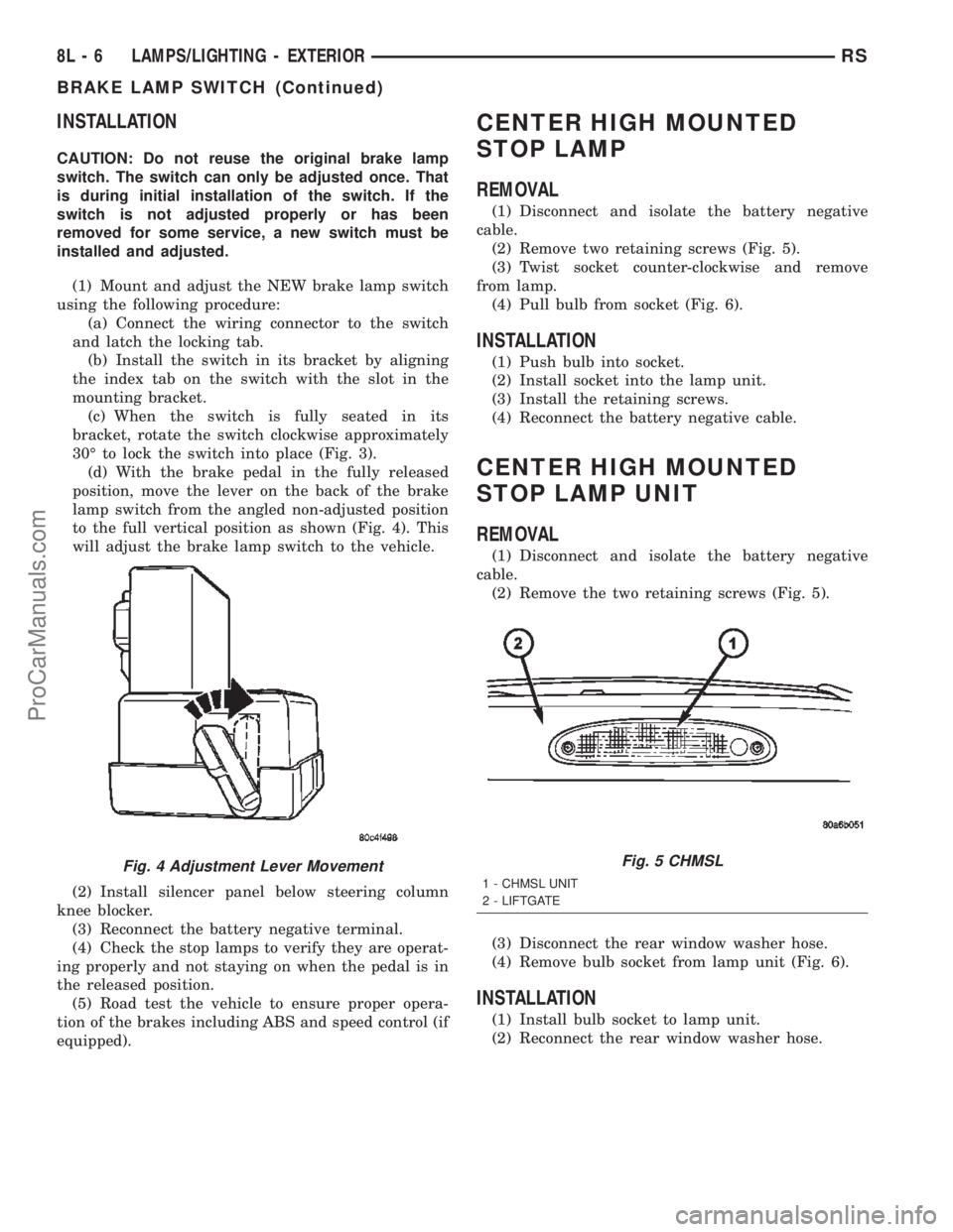
(1) Mount and adjust the NEW brake lamp switch
using the following procedure:
(a) Connect the wiring connector to the switch
and latch the locking tab.
(b) Install the switch in its bracket by aligning
the index tab on the switch with the slot in the
mounting bracket.
(c) When the switch is fully seated in its
bracket, rotate the switch clockwise approximately
30É to lock the switch into place (Fig. 3).
(d) With the brake pedal in the fully released
position, move the lever on the back of the brake
lamp switch from the angled non-adjusted position
to the full vertical position as shown (Fig. 4). This
will adjust the brake lamp switch to the vehicle.
(2) Install silencer panel below steering column
knee blocker.
(3) Reconnect the battery negative terminal.
(4) Check the stop lamps to verify they are operat-
ing properly and not staying on when the pedal is in
the released position.
(5) Road test the vehicle to ensure proper opera-
tion of the brakes including ABS and speed control (if
equipped).
CENTER HIGH MOUNTED
STOP LAMP
REMOVAL
(1) Disconnect and isolate the battery negative
cable.
(2) Remove two retaining screws (Fig. 5).
(3) Twist socket counter-clockwise and remove
from lamp.
(4) Pull bulb from socket (Fig. 6).
INSTALLATION
(1) Push bulb into socket.
(2) Install socket into the lamp unit.
(3) Install the retaining screws.
(4) Reconnect the battery negative cable.
CENTER HIGH MOUNTED
STOP LAMP UNIT
REMOVAL
(1) Disconnect and isolate the battery negative
cable.
(2) Remove the two retaining screws (Fig. 5).
(3) Disconnect the rear window washer hose.
(4) Remove bulb socket from lamp unit (Fig. 6).
INSTALLATION
(1) Install bulb socket to lamp unit.
(2) Reconnect the rear window washer hose.
Fig. 4 Adjustment Lever MovementFig. 5 CHMSL
1 - CHMSL UNIT
2 - LIFTGATE
8L - 6 LAMPS/LIGHTING - EXTERIORRS
BRAKE LAMP SWITCH (Continued)
ProCarManuals.com
Page 658 of 2399

WIRING
TABLE OF CONTENTS
page page
WIRING DIAGRAM INFORMATION....... 8W-01-1
COMPONENT INDEX.................. 8W-02-1
POWER DISTRIBUTION............... 8W-10-1
GROUND DISTRIBUTION.............. 8W-15-1
BUS COMMUNICATIONS.............. 8W-18-1
CHARGING SYSTEM.................. 8W-20-1
STARTING SYSTEM.................. 8W-21-1
FUEL/IGNITION SYSTEM.............. 8W-30-1
TRANSMISSION CONTROL SYSTEM..... 8W-31-1
VEHICLE SPEED CONTROL............ 8W-33-1
ANTILOCK BRAKES................... 8W-35-1
VEHICLE THEFT SECURITY SYSTEM..... 8W-39-1
INSTRUMENT CLUSTER............... 8W-40-1
HORN/CIGAR LIGHTER/POWER OUTLET . . 8W-41-1
AIR CONDITIONING-HEATER........... 8W-42-1
AIRBAG SYSTEM.................... 8W-43-1
INTERIOR LIGHTING.................. 8W-44-1
BODY CONTROL MODULE............. 8W-45-1MESSAGE CENTER................... 8W-46-1
AUDIO SYSTEM..................... 8W-47-1
REAR WINDOW DEFOGGER............ 8W-48-1
OVERHEAD CONSOLE................. 8W-49-1
FRONT LIGHTING.................... 8W-50-1
REAR LIGHTING..................... 8W-51-1
TURN SIGNALS...................... 8W-52-1
WIPERS............................ 8W-53-1
TRAILER TOW....................... 8W-54-1
POWER WINDOWS................... 8W-60-1
POWER DOOR LOCKS................ 8W-61-1
POWER MIRRORS................... 8W-62-1
POWER SEATS...................... 8W-63-1
SPLICE INFORMATION................ 8W-70-1
CONNECTOR PIN-OUTS............... 8W-80-1
CONNECTOR/GROUND/SPLICE
LOCATION........................ 8W-91-1
POWER DISTRIBUTION SYSTEM........ 8W-97-1 RSWIRING
8W-1
ProCarManuals.com
Page 676 of 2399

8W-02 COMPONENT INDEX
Component Page
A/C Compressor Clutch Relay............ 8W-42
A/C Compressor Clutch................. 8W-42
A/C- Heater Control.................... 8W-42
A/C Pressure Sensor................... 8W-42
A/C-Heater Control.................... 8W-42
Accelerator Pedal Position Sensor......... 8W-30
Accessory Relay....................... 8W-10
Adjustable Pedals Module............... 8W-30
Adjustable Pedals Switch................ 8W-30
Airbag Control Module.................. 8W-43
Ambient Temp Sensor.................. 8W-49
Antenna............................. 8W-47
Auto Shut Down Relay................. 8W-30
Auto Temp Control..................... 8W-42
Automatic Day/Night Mirror............. 8W-49
Back-Up Lamp Switch.................. 8W-51
Battery Temperature Sensor............. 8W-20
Battery............................. 8W-20
Blend Door Actuators................... 8W-42
Body Control Module................... 8W-45
Boost Pressure Sensor.................. 8W-30
B-Pillar Switches...................... 8W-61
Brake Lamp Switch................. 8W-30, 51
Brake Transmission Shift Interlock
Solenoid........................... 8W-31
Cabin Heater Assist.................... 8W-30
Camshaft Position Sensor............... 8W-30
CD Changer.......................... 8W-47
Center High Mounted Stop Lamp......... 8W-51
Cinch/Release Motors................... 8W-61
Clockspring.................. 8W-33, 41, 43, 47
Clutch Pedal Interlock Switch Jumper..... 8W-10
Clutch Pedal Interlock Switch............ 8W-10
Combination Relays.................... 8W-54
Controller Antilock Brake............... 8W-35
Crank Case Ventilation Heater........... 8W-30
Crankshaft Position Sensor.............. 8W-30
Cylinder Lock Switches................. 8W-39
Data Link Connector................... 8W-18
Diagnostic Junction Port................ 8W-18
Door Ajar Switches.................... 8W-39
Door Lock Motor/Ajar Switches........... 8W-61
Door Lock Switches.................... 8W-61
Driver Airbag......................... 8W-43
EGR Solenoid......................... 8W-30
Electric Wiper De-Icer.................. 8W-48
Engine Control Module................. 8W-30
Engine Coolant Temp Sensor............. 8W-30
Engine Oil Pressure Switch.............. 8W-30
EVAP/Purge Solenoid................... 8W-30
Evaporator Temperature Sensor.......... 8W-42
Floor Console Lamp.................... 8W-44Component Page
Fog Lamps........................... 8W-50
Front Blower Module................... 8W-42
Front Blower Motor Relay............... 8W-42
Front Blower Motor.................... 8W-42
Front Cigar Lighter.................... 8W-41
Front Control Module.................. 8W-10
Front Fog Lamp Relay.................. 8W-50
Front Intrusion Sensor................. 8W-39
Front Washer Pump Motor.............. 8W-53
Front Wiper On/Off Relay............... 8W-53
Fuel Heater.......................... 8W-30
Fuel Injectors........................ 8W-30
Fuel Pressure Solenoid................. 8W-30
Fuel Pump Module.................... 8W-30
Full Open Switches.................... 8W-61
Fuselink............................. 8W-10
Fuses............................... 8W-10
Generator............................ 8W-20
Glow Plug Relay...................... 8W-30
Glow Plugs........................... 8W-30
Grounds............................. 8W-15
Halo Lamp........................... 8W-44
Headlamp Leveling Motors.............. 8W-50
Headlamp Switch...................... 8W-50
Headlamp Washer Relay................ 8W-53
Headlamps........................... 8W-50
Heated Seat Backs..................... 8W-63
Heated Seat Cushions.................. 8W-63
Heated Seat Modules................... 8W-63
High Beam Lamps..................... 8W-50
High Note Horn....................... 8W-41
Horn Relay.......................... 8W-41
Idle Air Control Motor.................. 8W-30
Ignition Coil.......................... 8W-30
Ignition Switch....................... 8W-10
Inlet Air Temperature Sensor............ 8W-30
Instrument Cluster.................... 8W-40
Instrument Panel Switch Bank . . 8W-44, 52, 53, 63
Integrated Power Module................ 8W-10
Knock Sensor......................... 8W-30
License Lamp......................... 8W-51
Lift Pump Motor...................... 8W-30
Liftgate Ajar Switch................. 8W-39, 61
Liftgate Cinch/Release Motor............. 8W-61
Liftgate Cylinder Lock Switch............ 8W-39
Liftgate Flood Lamps................... 8W-44
Liftgate Right Pinch Sensor.............. 8W-61
Low Beam Lamps.................... 8W-50-9
Manifold Absolute Pressure Sensor........ 8W-30
Mass Air Flow Sensor.................. 8W-30
Memory Seat/Mirror Module.......... 8W-62, 63
Memory Set Switch.................... 8W-63
RS8W-02 COMPONENT INDEX8W-02-1
ProCarManuals.com
Page 677 of 2399

Component Page
Mid Reading Lamps.................... 8W-44
Mode Door Actuator.................... 8W-42
Multi- Function Switch........... 8W-50, 52, 53
Output Speed Sensor................... 8W-31
Overhead Console..................... 8W-49
Oxygen Sensor 1/1 Upstream............. 8W-30
Oxygen Sensor 1/2 Downstream.......... 8W-30
Park Lamp Relay...................... 8W-10
Park Lamps.......................... 8W-50
Park/Turn Signal Lamps................ 8W-50
Parking Brake Switch.................. 8W-40
Passenger Airbag...................... 8W-43
Positive Temperature Coefficients......... 8W-10
Power Liftgate Module.................. 8W-61
Power Liftgate Motor................... 8W-61
Power Mirror Switch................... 8W-62
Power Mirrors........................ 8W-62
Power Outlet......................... 8W-41
Power Seat Circuit Breaker.............. 8W-10
Power Seat Front Riser Motors........... 8W-63
Power Seat Horizontal Motors............ 8W-63
Power Seat Horizontal Position Sensors.... 8W-63
Power Seat Rear Riser Motors............ 8W-63
Power Seat Rear Riser Position Sensors.... 8W-63
Power Seat Recliner Motors.............. 8W-63
Power Seat Switches................... 8W-63
Power Window Circuit Breaker........... 8W-10
Power Window Motors.................. 8W-60
Power Window Switches................ 8W-60
Powertrain Control Module.............. 8W-30
Radiator Fan Relays................... 8W-42
Radiator Fans........................ 8W-42
Radio Choke.......................... 8W-47
Radio............................... 8W-47
Reading Lamps....................... 8W-44
Rear A/C-Heater Unit.................. 8W-42
Rear Auto Temp Control Switch........... 8W-42
Rear Blower Front Control Switch......... 8W-42
Rear Blower Motor Power Module......... 8W-42
Rear Blower Motor Relay................ 8W-42
Rear Blower Motor..................... 8W-42
Rear Blower Rear Control Switch......... 8W-42
Rear Intrusion Sensor.................. 8W-39Component Page
Rear Lamp Assemblies.................. 8W-51
Rear Mode Motor...................... 8W-42
Rear Power Outlet..................... 8W-41
Rear Temperature Motor................ 8W-42
Rear Washer Pump Motor............... 8W-53
Rear Window Defogger Grid............. 8W-48
Recirculation Door Actuator.............. 8W-42
Remote Keyless Entry Antenna........... 8W-61
Remote Radio Switches................. 8W-47
Repeater Lamps....................... 8W-52
Seat Airbag.......................... 8W-43
Seat Belt Tensioners................... 8W-43
Sentry Key Immobilizer Module.......... 8W-39
Side Impact Airbag Control Modules....... 8W-43
Siren............................... 8W-39
Sliding Door Control Modules............ 8W-61
Sliding Door Latch Sensing Switches....... 8W-61
Sliding Door Lock Motor/Ajar Switches..... 8W-61
Sliding Door Lock Motors............... 8W-61
Sliding Door Motors.................... 8W-61
Solenoid/Pressure Switch Assy............ 8W-31
Speakers............................ 8W-47
Speed Control Servo................... 8W-33
Speed Control Switches................. 8W-33
Splice Information..................... 8W-70
Starter Motor Relay.................... 8W-21
Starter Motor......................... 8W-21
Stop/Turn Signal Relays................ 8W-54
Thatcham Alarm Module................ 8W-39
Throttle Position Sensor................ 8W-30
Torque Converter Clutch Solenoid......... 8W-31
Traction Control Switch................. 8W-35
Trailer Tow Connector.................. 8W-54
Transmission Control Module............ 8W-31
Transmission Range Sensor.............. 8W-31
Turn Signal Lamps.................... 8W-52
TXV Solenoid......................... 8W-42
Vehicle Speed Sensor................... 8W-30
Vent Motors.......................... 8W-60
Visor/Vanity Lamps.................... 8W-44
Washer Fluid Level Switch.............. 8W-53
Water In Fuel Sensor................... 8W-30
Wheel Speed Sensors................... 8W-35
8W - 02 - 2 8W-02 COMPONENT INDEXRS
ProCarManuals.com
Page 1148 of 2399

8W-91 CONNECTOR/GROUND/SPLICE LOCATION
TABLE OF CONTENTS
page
CONNECTOR/GROUND/SPLICE LOCATION
DESCRIPTION..........................1
CONNECTOR/GROUND/SPLICE
LOCATION
DESCRIPTION
This section provides illustrations identifying con-
nector, ground, and splice locations in the vehicle.Connector, ground, and splice indexes are provided.
Use the wiring diagrams in each section for connec-
tor, ground, and splice identification. Refer to the
appropriate index for the proper figure number. For
items that are not shown in this section N/S is placed
in the Fig. column.
CONNECTORS
CONNECTOR NAME/NUMBER COLOR LOCATION FIG.
A/C Compressor Clutch LTGY Top of A/C Compressor 9, 10, 11, 13, 14
A/C-Heater Control C1 (MTC) BK/RD Rear of Control 15, 18, 20
A/C-Heater Control C2 (MTC) BK/BL Rear of Control 15, 18, 20
A/C Pressure Transducer GY At Throttle Body 9, 11, 12, 13
Accelerator Pedal Position Sensor
(Diesel)BK At Accelerator Pedal 36
Airbag Control Module YL/RD Right Side of Instrument Panel 15, 19, 20
Ambient Temperature Sensor BK On Radiator Closure Panel 1
ATC Remote Sensor Above ATC Control N/S
Automatic Day/Night Mirror BK At Mirror N/S
Autostick Switch BK Rear of Switch 16, 17, 18
Auto Temperature Control C1
(ATC)WT Rear of Control N/S
Auto Temperature Control C2
(ATC)BK Rear of Control N/S
Auto Temperature Control C3
(ATC)Rear of Control N/S
Back-Up Lamp Switch BK On Transmission 12
Battery Temperature Sensor
(Diesel)BK At Battery N/S
Blower Motor Resistor C1 (MTC) BK Right Side of HVAC N/S
Blower Motor Resistor C2 (MTC) Right Side of HVAC N/S
Body Control Module C1 BK Under Left Instrument Panel 35, 36
Body Control Module C2 BK/GN Under Left Instrument Panel 35, 36
Body Control Module C3 BK/WT Under Left Instrument Panel 35, 36
Body Control Module C4 BK/GY Under Left Instrument Panel 15, 16, 25
Body Control Module C5 BK Under Left Instrument Panel 15, 16, 25
RS8W-91 CONNECTOR/GROUND/SPLICE LOCATION8W-91-1
ProCarManuals.com
Page 1201 of 2399

WARNING: ON VEHICLES EQUIPPED WITH AIR-
BAGS, REFER TO RESTRAINTS BEFORE ATTEMPT-
ING ANY STEERING WHEEL, STEERING COLUMN,
SEAT OR INSTRUMENT PANEL COMPONENT DIAG-
NOSIS OR SERVICE. FAILURE TO TAKE THE
PROPER PRECAUTIONS COULD RESULT IN ACCI-
DENTAL AIRBAG DEPLOYMENT AND POSSIBLE
PERSONAL INJURY.
(1) Check the fused B(+) fuse in the Integrated
Power Module (IPM). If OK, go to Step 2. If not OK,
repair the shorted circuit or component as required
and replace the faulty fuse.
(2) Check for battery voltage at the fused B(+) fuse
in the IPM. If OK, go to Step 3. If not OK, repair the
open fused B(+) circuit to the IPM fuse as required.
(3)
Open the power outlet door. Check for continuity
between the inside circumference of the power outlet
receptacle and a good ground. There should be continu-
ity. If OK, go to Step 4. If not OK, go to Step 5.
(4) Check for battery voltage at the insulated con-
tact located at the back of the power outlet recepta-
cle. If not OK, go to Step 5.
(5) Disconnect and isolate the battery negative
cable. Remove the appropriate bezel. Check for conti-
nuity between the ground circuit cavity of the power
outlet wire harness connector and a good ground.
There should be continuity. If OK, go to Step 6. If not
OK, repair the open ground circuit to ground as
required.
(6) Connect the battery negative cable. Check for
battery voltage at the fused B(+) circuit cavity of the
power outlet wire harness connector. If OK, replace
the faulty power outlet receptacle. If not OK, repair
the open fused B(+) circuit to the IPM fuse as
required.
REMOVAL
(1) Disconnect and isolate the battery negative
cable.
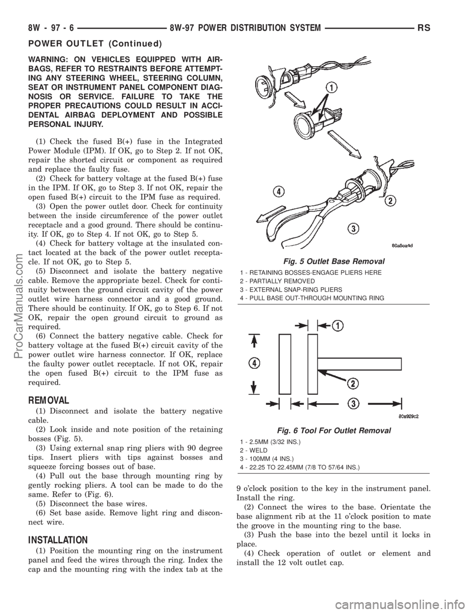
(2) Look inside and note position of the retaining
bosses (Fig. 5).
(3) Using external snap ring pliers with 90 degree
tips. Insert pliers with tips against bosses and
squeeze forcing bosses out of base.
(4) Pull out the base through mounting ring by
gently rocking pliers. A tool can be made to do the
same. Refer to (Fig. 6).
(5) Disconnect the base wires.
(6) Set base aside. Remove light ring and discon-
nect wire.
INSTALLATION
(1) Position the mounting ring on the instrument
panel and feed the wires through the ring. Index the
cap and the mounting ring with the index tab at the9 o'clock position to the key in the instrument panel.
Install the ring.
(2) Connect the wires to the base. Orientate the
base alignment rib at the 11 o'clock position to mate
the groove in the mounting ring to the base.
(3) Push the base into the bezel until it locks in
place.
(4) Check operation of outlet or element and
install the 12 volt outlet cap.
Fig. 5 Outlet Base Removal
1 - RETAINING BOSSES-ENGAGE PLIERS HERE
2 - PARTIALLY REMOVED
3 - EXTERNAL SNAP-RING PLIERS
4 - PULL BASE OUT-THROUGH MOUNTING RING
Fig. 6 Tool For Outlet Removal
1 - 2.5MM (3/32 INS.)
2 - WELD
3 - 100MM (4 INS.)
4 - 22.25 TO 22.45MM (7/8 TO 57/64 INS.)
8W - 97 - 6 8W-97 POWER DISTRIBUTION SYSTEMRS
POWER OUTLET (Continued)
ProCarManuals.com