2002 CHRYSLER TOWN AND COUNTRY index
[x] Cancel search: indexPage 1443 of 2399
(3) Install the six nuts attaching rear bumper rein-
forcement to frame rail extensions and tighten to 27
N´m (20 ft. lbs.) torque (Fig. 4).
(4) Install rear bumper fascia. (Refer to 13 -
FRAMES & BUMPERS/BUMPERS/REAR FASCIA -
INSTALLATION).
REAR FASCIA - SCUFF PAD
REMOVAL
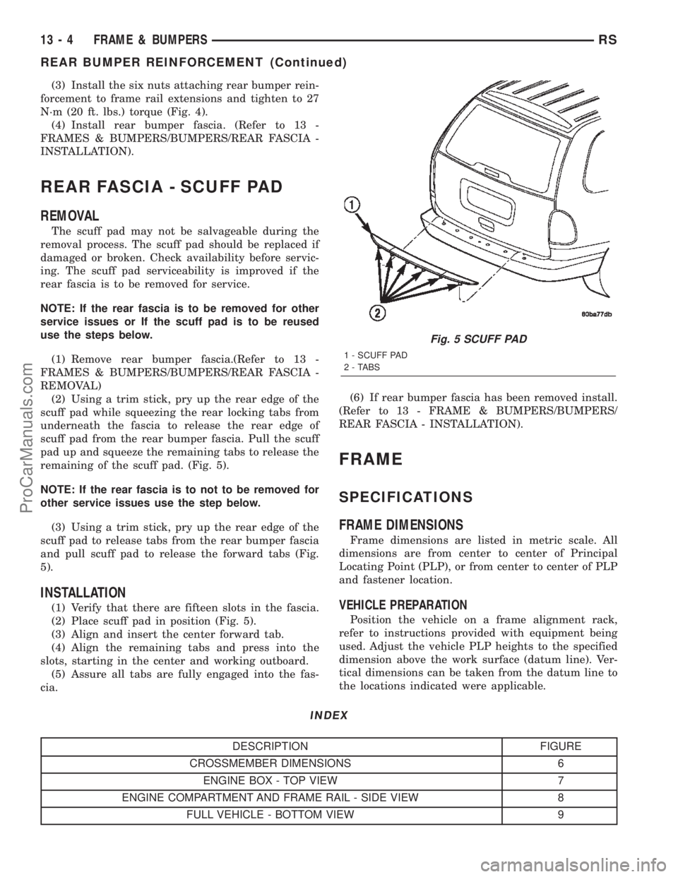
The scuff pad may not be salvageable during the
removal process. The scuff pad should be replaced if
damaged or broken. Check availability before servic-
ing. The scuff pad serviceability is improved if the
rear fascia is to be removed for service.
NOTE: If the rear fascia is to be removed for other
service issues or If the scuff pad is to be reused
use the steps below.
(1) Remove rear bumper fascia.(Refer to 13 -
FRAMES & BUMPERS/BUMPERS/REAR FASCIA -
REMOVAL)
(2) Using a trim stick, pry up the rear edge of the
scuff pad while squeezing the rear locking tabs from
underneath the fascia to release the rear edge of
scuff pad from the rear bumper fascia. Pull the scuff
pad up and squeeze the remaining tabs to release the
remaining of the scuff pad. (Fig. 5).
NOTE: If the rear fascia is to not to be removed for
other service issues use the step below.
(3) Using a trim stick, pry up the rear edge of the
scuff pad to release tabs from the rear bumper fascia
and pull scuff pad to release the forward tabs (Fig.
5).
INSTALLATION
(1) Verify that there are fifteen slots in the fascia.
(2) Place scuff pad in position (Fig. 5).
(3) Align and insert the center forward tab.
(4) Align the remaining tabs and press into the
slots, starting in the center and working outboard.
(5) Assure all tabs are fully engaged into the fas-
cia.(6) If rear bumper fascia has been removed install.
(Refer to 13 - FRAME & BUMPERS/BUMPERS/
REAR FASCIA - INSTALLATION).
FRAME
SPECIFICATIONS
FRAME DIMENSIONS
Frame dimensions are listed in metric scale. All
dimensions are from center to center of Principal
Locating Point (PLP), or from center to center of PLP
and fastener location.
VEHICLE PREPARATION
Position the vehicle on a frame alignment rack,
refer to instructions provided with equipment being
used. Adjust the vehicle PLP heights to the specified
dimension above the work surface (datum line). Ver-
tical dimensions can be taken from the datum line to
the locations indicated were applicable.
INDEX
DESCRIPTION FIGURE
CROSSMEMBER DIMENSIONS 6
ENGINE BOX - TOP VIEW 7
ENGINE COMPARTMENT AND FRAME RAIL - SIDE VIEW 8
FULL VEHICLE - BOTTOM VIEW 9
Fig. 5 SCUFF PAD
1 - SCUFF PAD
2 - TABS
13 - 4 FRAME & BUMPERSRS
REAR BUMPER REINFORCEMENT (Continued)
ProCarManuals.com
Page 1567 of 2399
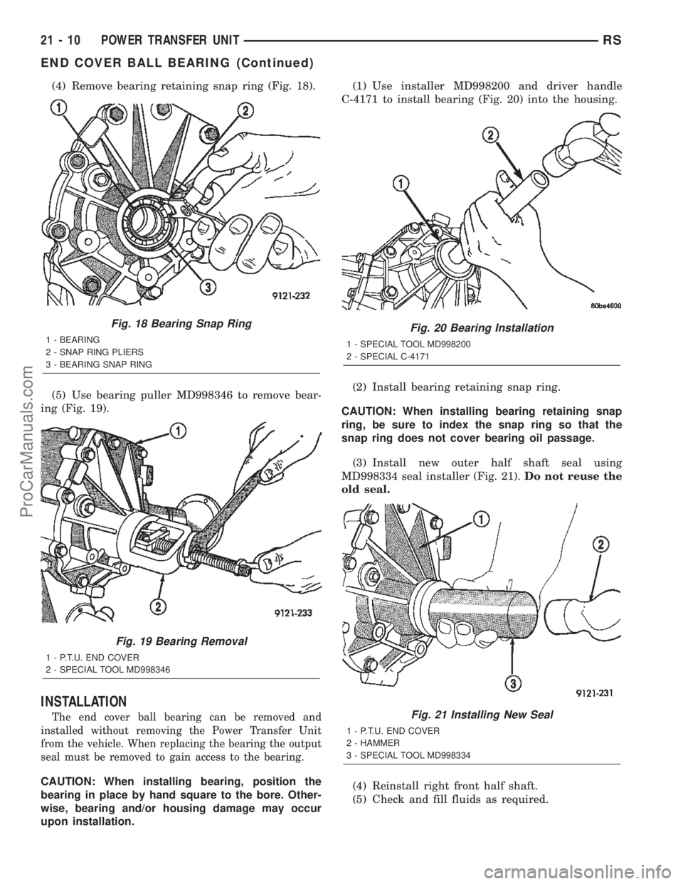
(4) Remove bearing retaining snap ring (Fig. 18).
(5) Use bearing puller MD998346 to remove bear-
ing (Fig. 19).
INSTALLATION
The end cover ball bearing can be removed and
installed without removing the Power Transfer Unit
from the vehicle. When replacing the bearing the output
seal must be removed to gain access to the bearing.
CAUTION: When installing bearing, position the
bearing in place by hand square to the bore. Other-
wise, bearing and/or housing damage may occur
upon installation.(1) Use installer MD998200 and driver handle
C-4171 to install bearing (Fig. 20) into the housing.
(2) Install bearing retaining snap ring.
CAUTION: When installing bearing retaining snap
ring, be sure to index the snap ring so that the
snap ring does not cover bearing oil passage.
(3) Install new outer half shaft seal using
MD998334 seal installer (Fig. 21).Do not reuse the
old seal.
(4) Reinstall right front half shaft.
(5) Check and fill fluids as required.
Fig. 18 Bearing Snap Ring
1 - BEARING
2 - SNAP RING PLIERS
3 - BEARING SNAP RING
Fig. 19 Bearing Removal
1 - P.T.U. END COVER
2 - SPECIAL TOOL MD998346
Fig. 20 Bearing Installation
1 - SPECIAL TOOL MD998200
2 - SPECIAL C-4171
Fig. 21 Installing New Seal
1 - P.T.U. END COVER
2 - HAMMER
3 - SPECIAL TOOL MD998334
21 - 10 POWER TRANSFER UNITRS
END COVER BALL BEARING (Continued)
ProCarManuals.com
Page 1577 of 2399
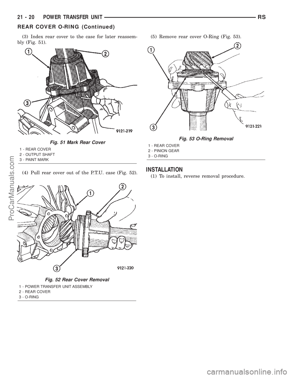
(3) Index rear cover to the case for later reassem-
bly (Fig. 51).
(4) Pull rear cover out of the P.T.U. case (Fig. 52).(5) Remove rear cover O-Ring (Fig. 53).
INSTALLATION
(1) To install, reverse removal procedure.
Fig. 52 Rear Cover Removal
1 - POWER TRANSFER UNIT ASSEMBLY
2 - REAR COVER
3 - O-RING
Fig. 51 Mark Rear Cover
1 - REAR COVER
2 - OUTPUT SHAFT
3 - PAINT MARK
Fig. 53 O-Ring Removal
1 - REAR COVER
2 - PINION GEAR
3 - O-RING
21 - 20 POWER TRANSFER UNITRS
REAR COVER O-RING (Continued)
ProCarManuals.com
Page 1653 of 2399
(4) Apply a bead of MopartSilicone Rubber Adhe-
sive Sealant to the adapter plate. Load differential
assembly into position and install adapter plate.
(5) Using Tool L-4435, index adapter plate until
bolt holes align.
(6) Install adapter plate-to-transaxle case bolts
and torque to 28 N´m (250 in. lbs.) torque.
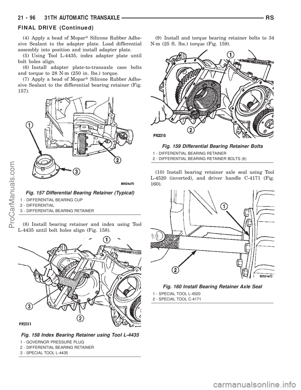
(7) Apply a bead of MopartSilicone Rubber Adhe-
sive Sealant to the differential bearing retainer (Fig.
157).
(8) Install bearing retainer and index using Tool
L-4435 until bolt holes align (Fig. 158).(9) Install and torque bearing retainer bolts to 34
N´m (25 ft. lbs.) torque (Fig. 159).
(10) Install bearing retainer axle seal using Tool
L-4520 (inverted), and driver handle C-4171 (Fig.
160).
Fig. 157 Differential Bearing Retainer (Typical)
1 - DIFFERENTIAL BEARING CUP
2 - DIFFERENTIAL
3 - DIFFERENTIAL BEARING RETAINER
Fig. 158 Index Bearing Retainer using Tool L-4435
1 - GOVERNOR PRESSURE PLUG
2 - DIFFERENTIAL BEARING RETAINER
3 - SPECIAL TOOL L-4435
Fig. 159 Differential Bearing Retainer Bolts
1 - DIFFERENTIAL BEARING RETAINER
2 - DIFFERENTIAL BEARING RETAINER BOLTS (6)
Fig. 160 Install Bearing Retainer Axle Seal
1 - SPECIAL TOOL L-4520
2 - SPECIAL TOOL C-4171
21 - 96 31TH AUTOMATIC TRANSAXLERS
FINAL DRIVE (Continued)
ProCarManuals.com
Page 1740 of 2399
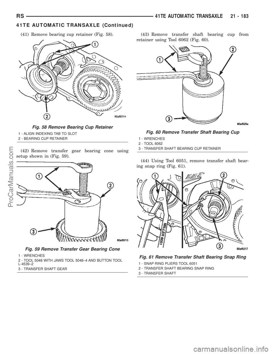
(41) Remove bearing cup retainer (Fig. 58).
(42) Remove transfer gear bearing cone using
setup shown in (Fig. 59).(43) Remove transfer shaft bearing cup from
retainer using Tool 6062 (Fig. 60).
(44) Using Tool 6051, remove transfer shaft bear-
ing snap ring (Fig. 61).
Fig. 58 Remove Bearing Cup Retainer
1 - ALIGN INDEXING TAB TO SLOT
2 - BEARING CUP RETAINER
Fig. 59 Remove Transfer Gear Bearing Cone
1 - WRENCHES
2 - TOOL 5048 WITH JAWS TOOL 5048±4 AND BUTTON TOOL
L-4539±2
3 - TRANSFER SHAFT GEAR
Fig. 60 Remove Transfer Shaft Bearing Cup
1 - WRENCHES
2 - TOOL 6062
3 - TRANSFER SHAFT BEARING CUP RETAINER
Fig. 61 Remove Transfer Shaft Bearing Snap Ring
1 - SNAP RING PLIERS TOOL 6051
2 - TRANSFER SHAFT BEARING SNAP RING
3 - TRANSFER SHAFT
RS41TE AUTOMATIC TRANSAXLE21 - 183
41TE AUTOMATIC TRANSAXLE (Continued)
ProCarManuals.com
Page 1756 of 2399
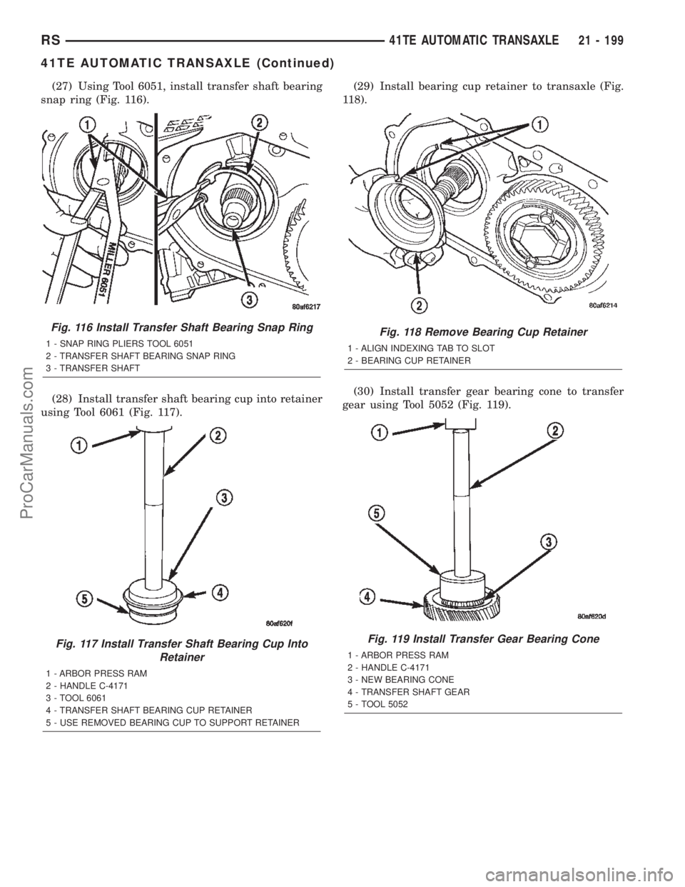
(27) Using Tool 6051, install transfer shaft bearing
snap ring (Fig. 116).
(28) Install transfer shaft bearing cup into retainer
using Tool 6061 (Fig. 117).(29) Install bearing cup retainer to transaxle (Fig.
118).
(30) Install transfer gear bearing cone to transfer
gear using Tool 5052 (Fig. 119).
Fig. 116 Install Transfer Shaft Bearing Snap Ring
1 - SNAP RING PLIERS TOOL 6051
2 - TRANSFER SHAFT BEARING SNAP RING
3 - TRANSFER SHAFT
Fig. 117 Install Transfer Shaft Bearing Cup Into
Retainer
1 - ARBOR PRESS RAM
2 - HANDLE C-4171
3 - TOOL 6061
4 - TRANSFER SHAFT BEARING CUP RETAINER
5 - USE REMOVED BEARING CUP TO SUPPORT RETAINER
Fig. 118 Remove Bearing Cup Retainer
1 - ALIGN INDEXING TAB TO SLOT
2 - BEARING CUP RETAINER
Fig. 119 Install Transfer Gear Bearing Cone
1 - ARBOR PRESS RAM
2 - HANDLE C-4171
3 - NEW BEARING CONE
4 - TRANSFER SHAFT GEAR
5 - TOOL 5052
RS41TE AUTOMATIC TRANSAXLE21 - 199
41TE AUTOMATIC TRANSAXLE (Continued)
ProCarManuals.com
Page 1963 of 2399
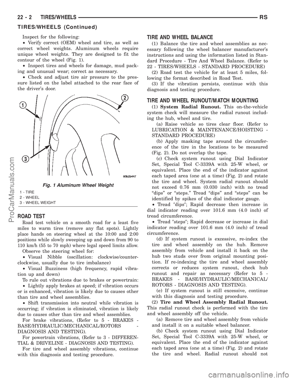
Inspect for the following:
²Verify correct (OEM) wheel and tire, as well as
correct wheel weights. Aluminum wheels require
unique wheel weights. They are designed to fit the
contour of the wheel (Fig. 1).
²Inspect tires and wheels for damage, mud pack-
ing and unusual wear; correct as necessary.
²Check and adjust tire air pressure to the pres-
sure listed on the label attached to the rear face of
the driver's door.
ROAD TEST
Road test vehicle on a smooth road for a least five
miles to warm tires (remove any flat spots). Lightly
place hands on steering wheel at the 10:00 and 2:00
positions while slowly sweeping up and down from 90 to
110 km/h (55 to 70 mph) where legal speed limits allow.
Observe the steering wheel for:
²Visual Nibble (oscillation: clockwise/counter-
clockwise, usually due to tire imbalance)
²Visual Buzziness (high frequency, rapid vibra-
tion up and down)
To rule out vibrations due to brakes or powertrain:
²Lightly apply brakes at speed; if vibration occurs
or is enhanced, vibration is likely due to causes other
than tire and wheel assemblies.
²
Shift transmission into neutral while vibration is
occurring; if vibration is eliminated, vibration is likely
due to causes other than tire and wheel assemblies.
For brake vibrations, (Refer to 5 - BRAKES -
BASE/HYDRAULIC/MECHANICAL/ROTORS -
DIAGNOSIS AND TESTING).
For powertrain vibrations, (Refer to 3 - DIFFEREN-
TIAL & DRIVELINE - DIAGNOSIS AND TESTING).
For tire and wheel assembly vibrations, continue
with this diagnosis and testing procedure.
TIRE AND WHEEL BALANCE
(1) Balance the tire and wheel assemblies as nec-
essary following the wheel balancer manufacturer's
instructions and using the information listed in Stan-
dard Procedure - Tire And Wheel Balance. (Refer to
22 - TIRES/WHEELS - STANDARD PROCEDURE)
(2) Road test the vehicle for at least 5 miles, fol-
lowing the format described in Road Test.
(3) If the vibration persists, continue with this
diagnosis and testing procedure.
TIRE AND WHEEL RUNOUT/MATCH MOUNTING
(1)System Radial Runout.This on-the-vehicle
system check will measure the radial runout includ-
ing the hub, wheel and tire.
(a) Raise vehicle so tires clear floor. (Refer to
LUBRICATION & MAINTENANCE/HOISTING -
STANDARD PROCEDURE)
(b) Apply masking tape around the circumfer-
ence of the tire in the locations to be measured
(Fig. 2). Do not overlap the tape.
(c) Check system runout using Dial Indicator
Set, Special Tool C-3339A with 25-W wheel, or
equivalent. Place the end of the indicator against
each taped area (one at a time) (Fig. 2) and rotate
the tire and wheel. System radial runout should
not exceed 0.76 mm (0.030 inch) with no tread
ªdipsº or ªsteps.º Tread ªdipsº and ªstepsº can be
identified by spikes of the dial indicator gauge.
²Tread9dips9; Rapid decrease then increase in
dial indicator reading over 101.6 mm (4.0 inch) of
tread circumference.
²Tread9steps9; Rapid decrease or increase in dial
indicator reading over 101.6 mm (4.0 inch) of tread
circumference.
(d) If system runout is excessive, re-index the
tire and wheel assembly on the hub. Remove
assembly from vehicle and install it back on the
hub two studs over from original mounting posi-
tion. If re-indexing the tire and wheel assembly
corrects or reduces system runout, check hub
runout and repair as necessary (Refer to 5 -
BRAKES - BASE/HYDRAULIC/MECHANICAL/
ROTORS - DIAGNOSIS AND TESTING).
(e) If system runout is still excessive, continue
with this diagnosis and testing procedure.
(2)Tire and Wheel Assembly Radial Runout.
This radial runout check is performed with the tire
and wheel assembly off the vehicle.
(a) Remove tire and wheel assembly from vehicle
and install it on a suitable wheel balancer.
(b) Check system runout using Dial Indicator
Set, Special Tool C-3339A with 25-W wheel, or
equivalent. Place the end of the indicator against
each taped area (one at a time) (Fig. 2) and rotate
the tire and wheel. Radial runout should not
Fig. 1 Aluminum Wheel Weight
1 - TIRE
2 - WHEEL
3 - WHEEL WEIGHT
22 - 2 TIRES/WHEELSRS
TIRES/WHEELS (Continued)
ProCarManuals.com
Page 1964 of 2399
exceed 0.76 mm (0.030 inch) with no tread ªdipsº
or ªsteps.º Tread ªdipsº and ªstepsº can be identi-
fied by spikes of the dial indicator gauge.
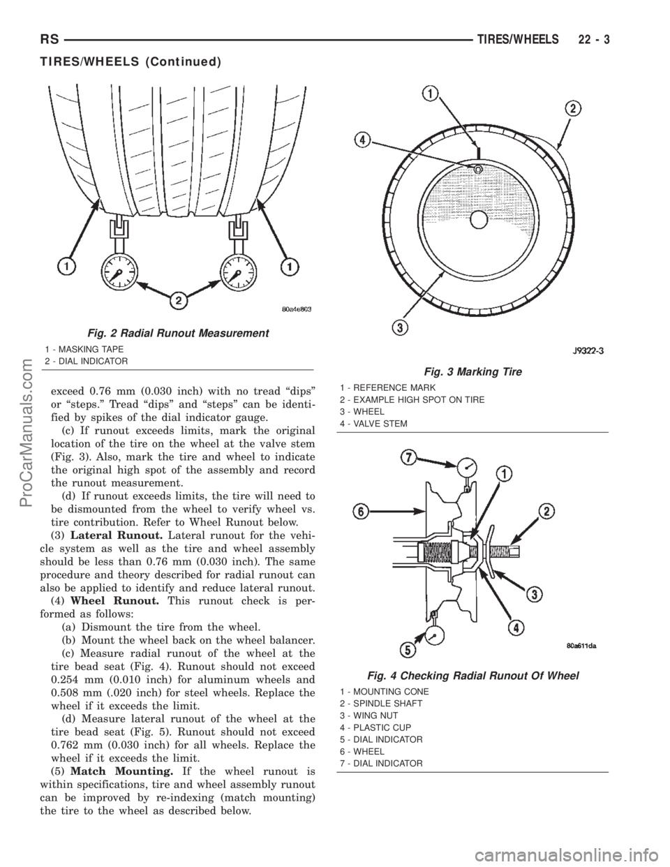
(c) If runout exceeds limits, mark the original
location of the tire on the wheel at the valve stem
(Fig. 3). Also, mark the tire and wheel to indicate
the original high spot of the assembly and record
the runout measurement.
(d) If runout exceeds limits, the tire will need to
be dismounted from the wheel to verify wheel vs.
tire contribution. Refer to Wheel Runout below.
(3)Lateral Runout.Lateral runout for the vehi-
cle system as well as the tire and wheel assembly
should be less than 0.76 mm (0.030 inch). The same
procedure and theory described for radial runout can
also be applied to identify and reduce lateral runout.
(4)Wheel Runout.This runout check is per-
formed as follows:
(a) Dismount the tire from the wheel.
(b) Mount the wheel back on the wheel balancer.
(c) Measure radial runout of the wheel at the
tire bead seat (Fig. 4). Runout should not exceed
0.254 mm (0.010 inch) for aluminum wheels and
0.508 mm (.020 inch) for steel wheels. Replace the
wheel if it exceeds the limit.
(d) Measure lateral runout of the wheel at the
tire bead seat (Fig. 5). Runout should not exceed
0.762 mm (0.030 inch) for all wheels. Replace the
wheel if it exceeds the limit.
(5)Match Mounting.If the wheel runout is
within specifications, tire and wheel assembly runout
can be improved by re-indexing (match mounting)
the tire to the wheel as described below.
Fig. 2 Radial Runout Measurement
1 - MASKING TAPE
2 - DIAL INDICATOR
Fig. 3 Marking Tire
1 - REFERENCE MARK
2 - EXAMPLE HIGH SPOT ON TIRE
3 - WHEEL
4 - VALVE STEM
Fig. 4 Checking Radial Runout Of Wheel
1 - MOUNTING CONE
2 - SPINDLE SHAFT
3 - WING NUT
4 - PLASTIC CUP
5 - DIAL INDICATOR
6 - WHEEL
7 - DIAL INDICATOR
RSTIRES/WHEELS22-3
TIRES/WHEELS (Continued)
ProCarManuals.com