2002 CHRYSLER TOWN AND COUNTRY fuel tank removal
[x] Cancel search: fuel tank removalPage 1460 of 2399
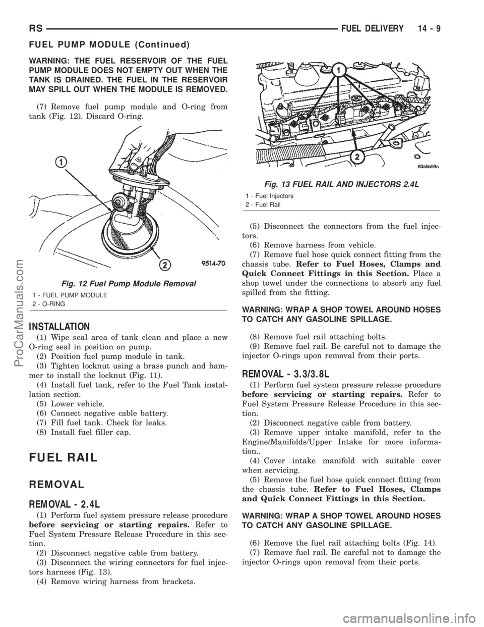
WARNING: THE FUEL RESERVOIR OF THE FUEL
PUMP MODULE DOES NOT EMPTY OUT WHEN THE
TANK IS DRAINED. THE FUEL IN THE RESERVOIR
MAY SPILL OUT WHEN THE MODULE IS REMOVED.
(7) Remove fuel pump module and O-ring from
tank (Fig. 12). Discard O-ring.
INSTALLATION
(1) Wipe seal area of tank clean and place a new
O-ring seal in position on pump.
(2) Position fuel pump module in tank.
(3) Tighten locknut using a brass punch and ham-
mer to install the locknut (Fig. 11).
(4) Install fuel tank, refer to the Fuel Tank instal-
lation section.
(5) Lower vehicle.
(6) Connect negative cable battery.
(7) Fill fuel tank. Check for leaks.
(8) Install fuel filler cap.
FUEL RAIL
REMOVAL
REMOVAL - 2.4L
(1) Perform fuel system pressure release procedure
before servicing or starting repairs.Refer to
Fuel System Pressure Release Procedure in this sec-
tion.
(2) Disconnect negative cable from battery.
(3) Disconnect the wiring connectors for fuel injec-
tors harness (Fig. 13).
(4) Remove wiring harness from brackets.(5) Disconnect the connectors from the fuel injec-
tors.
(6) Remove harness from vehicle.
(7) Remove fuel hose quick connect fitting from the
chassis tube.Refer to Fuel Hoses, Clamps and
Quick Connect Fittings in this Section.Place a
shop towel under the connections to absorb any fuel
spilled from the fitting.
WARNING: WRAP A SHOP TOWEL AROUND HOSES
TO CATCH ANY GASOLINE SPILLAGE.
(8) Remove fuel rail attaching bolts.
(9) Remove fuel rail. Be careful not to damage the
injector O-rings upon removal from their ports.
REMOVAL - 3.3/3.8L
(1) Perform fuel system pressure release procedure
before servicing or starting repairs.Refer to
Fuel System Pressure Release Procedure in this sec-
tion.
(2) Disconnect negative cable from battery.
(3) Remove upper intake manifold, refer to the
Engine/Manifolds/Upper Intake for more informa-
tion..
(4) Cover intake manifold with suitable cover
when servicing.
(5) Remove the fuel hose quick connect fitting from
the chassis tube.Refer to Fuel Hoses, Clamps
and Quick Connect Fittings in this Section.
WARNING: WRAP A SHOP TOWEL AROUND HOSES
TO CATCH ANY GASOLINE SPILLAGE.
(6) Remove the fuel rail attaching bolts (Fig. 14).
(7) Remove fuel rail. Be careful not to damage the
injector O-rings upon removal from their ports.
Fig. 12 Fuel Pump Module Removal
1 - FUEL PUMP MODULE
2 - O-RING
Fig. 13 FUEL RAIL AND INJECTORS 2.4L
1 - Fuel Injectors
2 - Fuel Rail
RSFUEL DELIVERY14-9
FUEL PUMP MODULE (Continued)
ProCarManuals.com
Page 1462 of 2399
REMOVAL
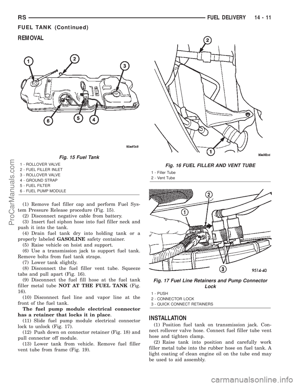
(1) Remove fuel filler cap and perform Fuel Sys-
tem Pressure Release procedure (Fig. 15).
(2) Disconnect negative cable from battery.
(3) Insert fuel siphon hose into fuel filler neck and
push it into the tank.
(4) Drain fuel tank dry into holding tank or a
properly labeledGASOLINEsafety container.
(5) Raise vehicle on hoist and support.
(6) Use a transmission jack to support fuel tank.
Remove bolts from fuel tank straps.
(7) Lower tank slightly.
(8) Disconnect the fuel filler vent tube. Squeeze
tabs and pull apart (Fig. 16).
(9) Disconnect the fuel fill hose at the fuel tank
filler metal tubeNOT AT THE FUEL TANK(Fig.
16).
(10) Disconnect fuel line and vapor line at the
front of the fuel tank.
The fuel pump module electrical connector
has a retainer that locks it in place.
(11) Slide fuel pump module electrical connector
lock to unlock (Fig. 17).
(12) Push down on connector retainer (Fig. 18) and
pull connector off module.
(13) Lower tank from vehicle. Remove fuel filler
vent tube from frame (Fig. 19).
INSTALLATION
(1) Position fuel tank on transmission jack. Con-
nect rollover valve hose. Connect fuel filler tube vent
hose and tighten clamp.
(2) Raise tank into position and carefully work
filler metal tube into the rubber hose on fuel tank. A
light coating of clean engine oil on the tube end may
be used to aid assembly.
Fig. 15 Fuel Tank
1 - ROLLOVER VALVE
2 - FUEL FILLER INLET
3 - ROLLOVER VALVE
4 - GROUND STRAP
5 - FUEL FILTER
6 - FUEL PUMP MODULEFig. 16 FUEL FILLER AND VENT TUBE
1 - Filler Tube
2 - Vent Tube
Fig. 17 Fuel Line Retainers and Pump Connector
Lock
1 - PUSH
2 - CONNECTOR LOCK
3 - QUICK CONNECT RETAINERS
RSFUEL DELIVERY14-11
FUEL TANK (Continued)
ProCarManuals.com
Page 1463 of 2399
(3) Feed filler vent line thru frame rail. Careful
not to cross lines.
(4) Tighten strap bolts to 54 N´m (40 ft. lbs.)
torque. Tighten T strap bolt to 28.2 N´m (250 in.
lbs.). Remove transmission jack.
(5) Tighten filler hose clamp to 3.3 N´m (30 in.
lbs.).
CAUTION: Ensure straps are not twisted or bent
before or after tightening strap nuts.
(6) Connect fuel pump/module electrical connector.
Place retainer in locked position.(7) Lubricate the fuel supply line with clean 30
weight engine oil, install the quick connect fuel fit-
ting. Refer to Tube/Fitting Assembly in the Fuel
Delivery section of this section.
(8) Attach filler vent line to filler tube. Pull on
connector to make sure of connection.
(9) Fill fuel tank, replace cap, and connect battery
negative cable.
(10) Use the DRBIIItscan tool to pressurize the
fuel system. Check for leaks.
FUEL TANK FILLER TUBE
REMOVAL
(1) Disconnect the negative battery cable.
(2) Remove the 3 screws at the filler door.
(3) Raise and support vehicle
(4) Remove the left rear tire.
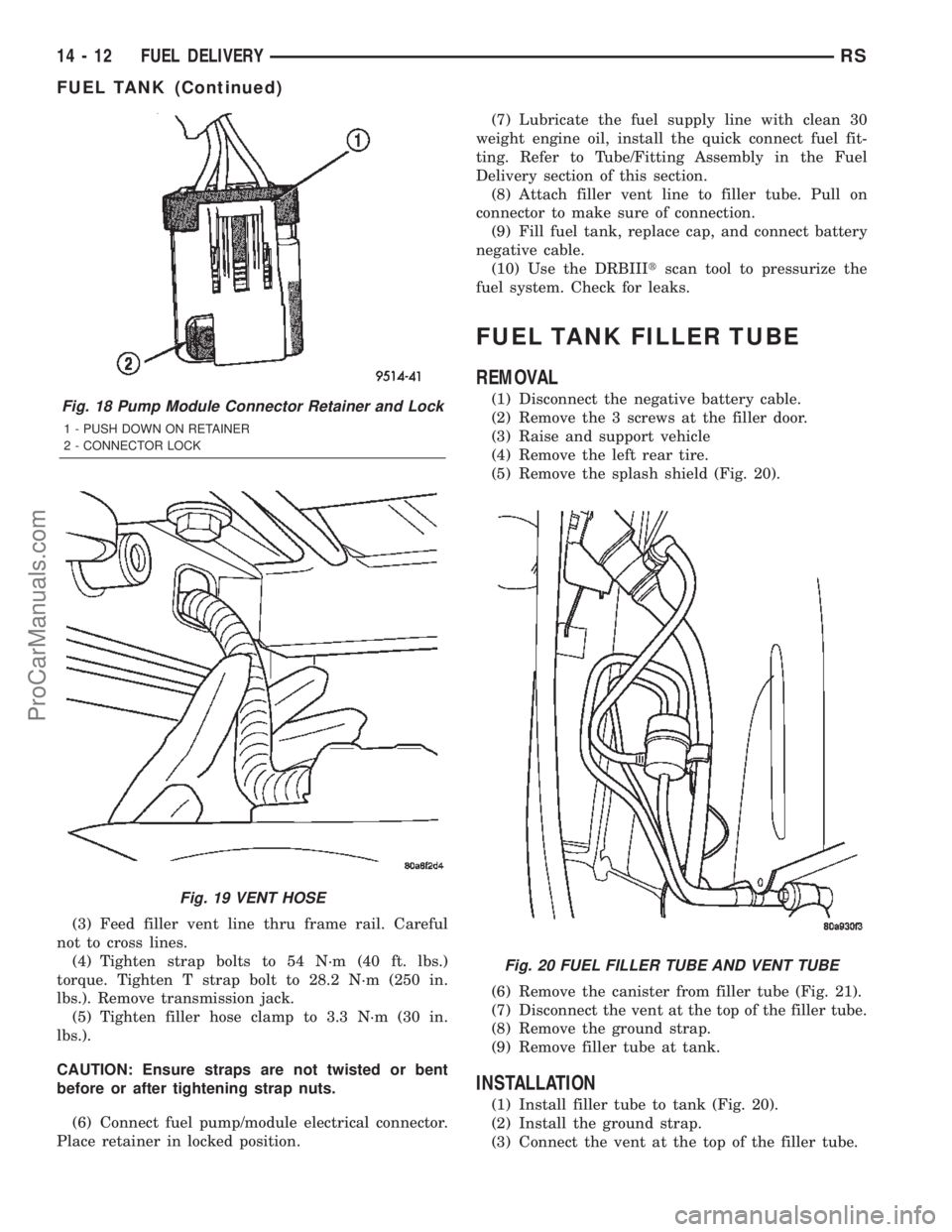
(5) Remove the splash shield (Fig. 20).
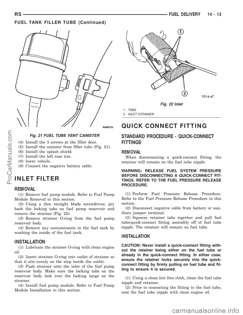
(6) Remove the canister from filler tube (Fig. 21).
(7) Disconnect the vent at the top of the filler tube.
(8) Remove the ground strap.
(9) Remove filler tube at tank.
INSTALLATION
(1) Install filler tube to tank (Fig. 20).
(2) Install the ground strap.
(3) Connect the vent at the top of the filler tube.
Fig. 18 Pump Module Connector Retainer and Lock
1 - PUSH DOWN ON RETAINER
2 - CONNECTOR LOCK
Fig. 19 VENT HOSE
Fig. 20 FUEL FILLER TUBE AND VENT TUBE
14 - 12 FUEL DELIVERYRS
FUEL TANK (Continued)
ProCarManuals.com
Page 1464 of 2399
(4) Install the 3 screws at the filler door.
(5) Install the canister from filler tube (Fig. 21).
(6) Install the splash shield.
(7) Install the left rear tire.
(8) lower vehicle.
(9) Connect the negative battery cable.
INLET FILTER
REMOVAL
(1) Remove fuel pump module. Refer to Fuel Pump
Module Removal in this section.
(2) Using a thin straight blade screwdriver, pry
back the locking tabs on fuel pump reservoir and
remove the strainer (Fig. 22).
(3) Remove strainer O-ring from the fuel pump
reservoir body.
(4) Remove any contaminants in the fuel tank by
washing the inside of the fuel tank.
INSTALLATION
(1) Lubricate the strainer O-ring with clean engine
oil.
(2) Insert strainer O-ring into outlet of strainer so
that it sits evenly on the step inside the outlet.
(3) Push strainer onto the inlet of the fuel pump
reservoir body. Make sure the locking tabs on the
reservoir body lock over the locking tangs on the
strainer.
(4) Install fuel pump module. Refer to Fuel Pump
Module Installation in this section.
QUICK CONNECT FITTING
STANDARD PROCEDURE - QUICK-CONNECT
FITTINGS
REMOVAL
When disconnecting a quick-connect fitting, the
retainer will remain on the fuel tube nipple.
WARNING: RELEASE FUEL SYSTEM PRESSURE
BEFORE DISCONNECTING A QUICK-CONNECT FIT-
TINGS. REFER TO THE FUEL PRESSURE RELEASE
PROCEDURE.
(1) Perform Fuel Pressure Release Procedure.
Refer to the Fuel Pressure Release Procedure in this
section.
(2) Disconnect negative cable from battery or aux-
iliary jumper terminal.
(3) Squeeze retainer tabs together and pull fuel
tube/quick-connect fitting assembly off of fuel tube
nipple. The retainer will remain on fuel tube.
INSTALLATION
CAUTION: Never install a quick-connect fitting with-
out the retainer being either on the fuel tube or
already in the quick-connect fitting. In either case,
ensure the retainer locks securely into the quick-
connect fitting by firmly pulling on fuel tube and fit-
ting to ensure it is secured.
(1) Using a clean lint free cloth, clean the fuel tube
nipple and retainer.
(2) Prior to connecting the fitting to the fuel tube,
coat the fuel tube nipple with clean engine oil.
Fig. 21 FUEL TUBE VENT CANISTER
Fig. 22 Inlet
1 - TABS
2 - INLET STRAINER
RSFUEL DELIVERY14-13
FUEL TANK FILLER TUBE (Continued)
ProCarManuals.com
Page 1493 of 2399
Refer to the maintenance schedules for the recom-
mended fuel filter replacement intervals.
For draining of water from canister, refer to Fuel
Filter/Water Separator Removal/Installation section.
A Water-In-Fuel (WIF) sensor is part of the fuel fil-
ter cap. Refer to Water-In-Fuel Sensor Description/
Operation.
The fuel heater is installed into the filter/separator
housing above the fuel filter. Refer to Fuel Heater
Description/Operation.
FUEL LINES
DESCRIPTION
DESCRIPTION
All fuel lines up to the fuel injection pump are con-
sidered low-pressure. This includes the fuel lines
from: the fuel tank to the fuel transfer pump, and
the fuel transfer pump to the fuel injection pump.
The fuel return lines and the fuel drain lines are also
considered low-pressure lines. High-pressure lines
are used between the fuel injection pump and the
fuel injectors. Also refer to High-Pressure Fuel Lines
Description/Operation.
DESCRIPTION - HIGH PRESSURE FUEL LINES
The high-pressure fuel lines are the 4 lines located
between the fuel injection pump and the fuel injec-
torsctor tubes. All other fuel lines are considered low-
pressure lines.
OPERATION - HIGH PRESSURE FUEL LINES
CAUTION: The high-pressure fuel lines cannot con-
tact each other or other components. Do not
attempt to weld high-pressure fuel lines or to repair
lines that are damaged. If lines are ever kinked or
bent, they must be replaced. Use only the recom-
mended lines when replacement of high-pressure
fuel line is necessary.
High-pressure fuel lines deliver fuel under
extremely high pressure from the injection pump to
the fuel injectors. The lines expand and contract from
the high-pressure fuel pulses generated during the
injection process. All high-pressure fuel lines are of
the same length and inside diameter. Correct high-
pressure fuel line usage and installation is critical to
smooth engine operation.
WARNING: USE EXTREME CAUTION WHEN
INSPECTING FOR HIGH-PRESSURE FUEL LEAKS.
INSPECT FOR HIGH-PRESSURE FUEL LEAKS WITH
A SHEET OF CARDBOARD. HIGH FUEL INJECTIONPRESSURE CAN CAUSE PERSONAL INJURY IF
CONTACT IS MADE WITH THE SKIN.
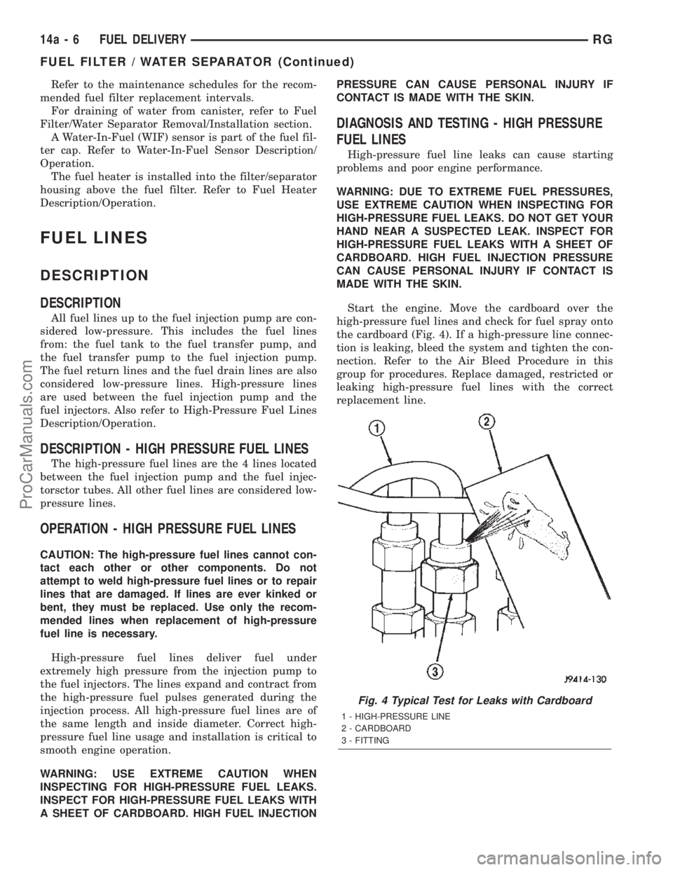
DIAGNOSIS AND TESTING - HIGH PRESSURE
FUEL LINES
High-pressure fuel line leaks can cause starting
problems and poor engine performance.
WARNING: DUE TO EXTREME FUEL PRESSURES,
USE EXTREME CAUTION WHEN INSPECTING FOR
HIGH-PRESSURE FUEL LEAKS. DO NOT GET YOUR
HAND NEAR A SUSPECTED LEAK. INSPECT FOR
HIGH-PRESSURE FUEL LEAKS WITH A SHEET OF
CARDBOARD. HIGH FUEL INJECTION PRESSURE
CAN CAUSE PERSONAL INJURY IF CONTACT IS
MADE WITH THE SKIN.
Start the engine. Move the cardboard over the
high-pressure fuel lines and check for fuel spray onto
the cardboard (Fig. 4). If a high-pressure line connec-
tion is leaking, bleed the system and tighten the con-
nection. Refer to the Air Bleed Procedure in this
group for procedures. Replace damaged, restricted or
leaking high-pressure fuel lines with the correct
replacement line.
Fig. 4 Typical Test for Leaks with Cardboard
1 - HIGH-PRESSURE LINE
2 - CARDBOARD
3 - FITTING
14a - 6 FUEL DELIVERYRG
FUEL FILTER / WATER SEPARATOR (Continued)
ProCarManuals.com
Page 1494 of 2399
CAUTION: The high-pressure fuel lines cannot con-
tact each other or other components. Do not
attempt to weld high-pressure fuel lines or to repair
lines that are damaged. Only use the recommended
lines when replacement of high-pressure fuel line is
necessary.
FUEL TRANSFER PUMP
DESCRIPTION
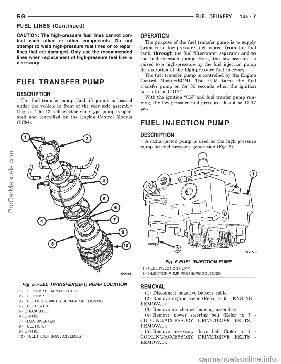
The fuel transfer pump (fuel lift pump) is located
under the vehicle in front of the rear axle assembly
(Fig. 5). The 12±volt electric vane-type pump is oper-
ated and controlled by the Engine Control Module
(ECM).
OPERATION
The purpose of the fuel transfer pump is to supply
(transfer) a low-pressure fuel source:fromthe fuel
tank,throughthe fuel filter/water separator andto
the fuel injection pump. Here, the low-pressure is
raised to a high-pressure by the fuel injection pump
for operation of the high-pressure fuel injectors.
The fuel transfer pump is controlled by the Engine
Control Module(ECM). The ECM turns the fuel
transfer pump on for 30 seconds when the ignition
ket is turned ªONº.
With the ignition ªONº and fuel tranfer pump run-
ning, the low-pressure fuel pressure should be 13-17
psi.
FUEL INJECTION PUMP
DESCRIPTION
A radial-piston pump is used as the high pressure
pump for fuel pressure generation (Fig. 6).
REMOVAL
(1) Disconnect negative battery cable.
(2) Remove engine cover (Refer to 9 - ENGINE -
REMOVAL)
(3) Remove air cleaner housing assembly.
(4) Remove power steering belt (Refer to 7 -
COOLING/ACCESSORY DRIVE/DRIVE BELTS -
REMOVAL).
(5) Remove accessory drive belt (Refer to 7 -
COOLING/ACCESSORY DRIVE/DRIVE BELTS -
REMOVAL).
Fig. 5 FUEL TRANSFER(LIFT) PUMP LOCATION
1 - LIFT PUMP RETAINING BOLTS
2 - LIFT PUMP
3 - FUEL FILTER/WATER SEPARATOR HOUSING
4 - FUEL HEATER
5 - CHECK BALL
6 - O-RING
7 - FLOW DIVERTER
8 - FUEL FILTER
9 - O-RING
10 - FUEL FILTER BOWL ASSEMBLY
Fig. 6 FUEL INJECTION PUMP
1 - FUEL INJECTION PUMP
2 - INJECTION PUMP PRESSURE SOLENOID
RGFUEL DELIVERY14a-7
FUEL LINES (Continued)
ProCarManuals.com
Page 1499 of 2399
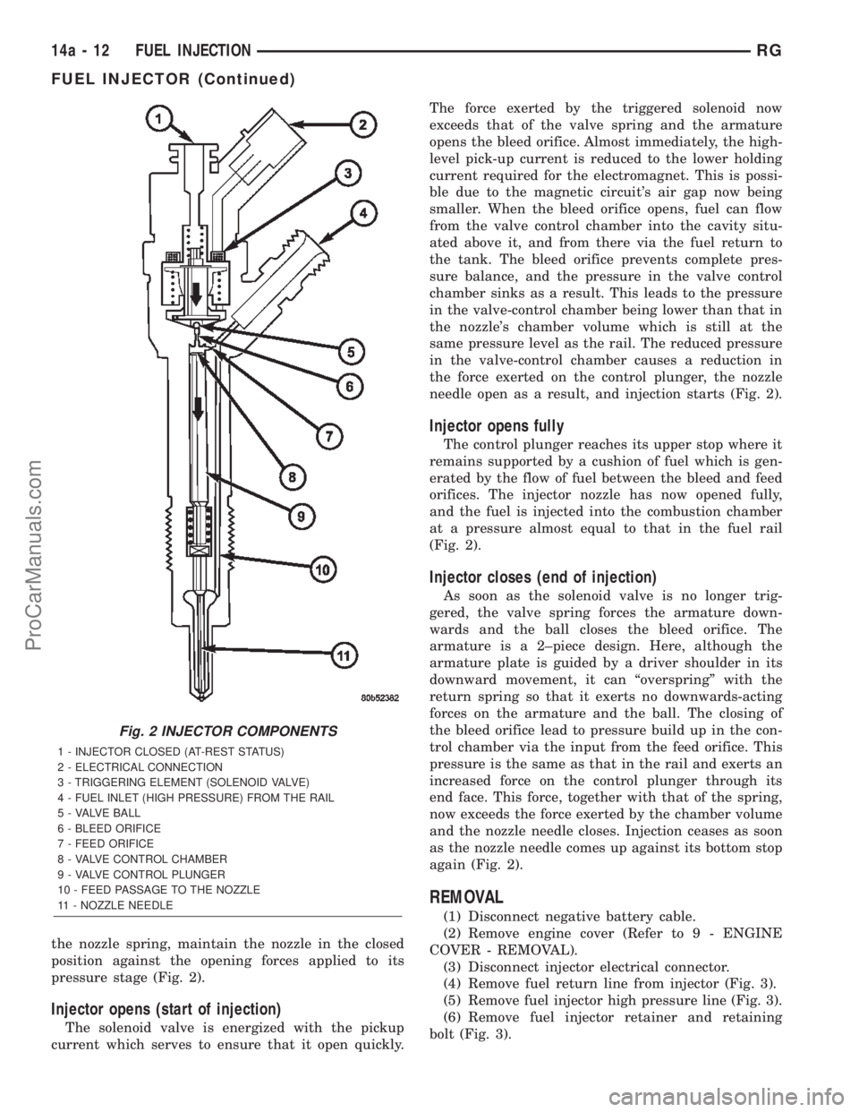
the nozzle spring, maintain the nozzle in the closed
position against the opening forces applied to its
pressure stage (Fig. 2).
Injector opens (start of injection)
The solenoid valve is energized with the pickup
current which serves to ensure that it open quickly.The force exerted by the triggered solenoid now
exceeds that of the valve spring and the armature
opens the bleed orifice. Almost immediately, the high-
level pick-up current is reduced to the lower holding
current required for the electromagnet. This is possi-
ble due to the magnetic circuit's air gap now being
smaller. When the bleed orifice opens, fuel can flow
from the valve control chamber into the cavity situ-
ated above it, and from there via the fuel return to
the tank. The bleed orifice prevents complete pres-
sure balance, and the pressure in the valve control
chamber sinks as a result. This leads to the pressure
in the valve-control chamber being lower than that in
the nozzle's chamber volume which is still at the
same pressure level as the rail. The reduced pressure
in the valve-control chamber causes a reduction in
the force exerted on the control plunger, the nozzle
needle open as a result, and injection starts (Fig. 2).
Injector opens fully
The control plunger reaches its upper stop where it
remains supported by a cushion of fuel which is gen-
erated by the flow of fuel between the bleed and feed
orifices. The injector nozzle has now opened fully,
and the fuel is injected into the combustion chamber
at a pressure almost equal to that in the fuel rail
(Fig. 2).
Injector closes (end of injection)
As soon as the solenoid valve is no longer trig-
gered, the valve spring forces the armature down-
wards and the ball closes the bleed orifice. The
armature is a 2±piece design. Here, although the
armature plate is guided by a driver shoulder in its
downward movement, it can ªoverspringº with the
return spring so that it exerts no downwards-acting
forces on the armature and the ball. The closing of
the bleed orifice lead to pressure build up in the con-
trol chamber via the input from the feed orifice. This
pressure is the same as that in the rail and exerts an
increased force on the control plunger through its
end face. This force, together with that of the spring,
now exceeds the force exerted by the chamber volume
and the nozzle needle closes. Injection ceases as soon
as the nozzle needle comes up against its bottom stop
again (Fig. 2).
REMOVAL
(1) Disconnect negative battery cable.
(2) Remove engine cover (Refer to 9 - ENGINE
COVER - REMOVAL).
(3) Disconnect injector electrical connector.
(4) Remove fuel return line from injector (Fig. 3).
(5) Remove fuel injector high pressure line (Fig. 3).
(6) Remove fuel injector retainer and retaining
bolt (Fig. 3).
Fig. 2 INJECTOR COMPONENTS
1 - INJECTOR CLOSED (AT-REST STATUS)
2 - ELECTRICAL CONNECTION
3 - TRIGGERING ELEMENT (SOLENOID VALVE)
4 - FUEL INLET (HIGH PRESSURE) FROM THE RAIL
5 - VALVE BALL
6 - BLEED ORIFICE
7 - FEED ORIFICE
8 - VALVE CONTROL CHAMBER
9 - VALVE CONTROL PLUNGER
10 - FEED PASSAGE TO THE NOZZLE
11 - NOZZLE NEEDLE
14a - 12 FUEL INJECTIONRG
FUEL INJECTOR (Continued)
ProCarManuals.com
Page 2058 of 2399
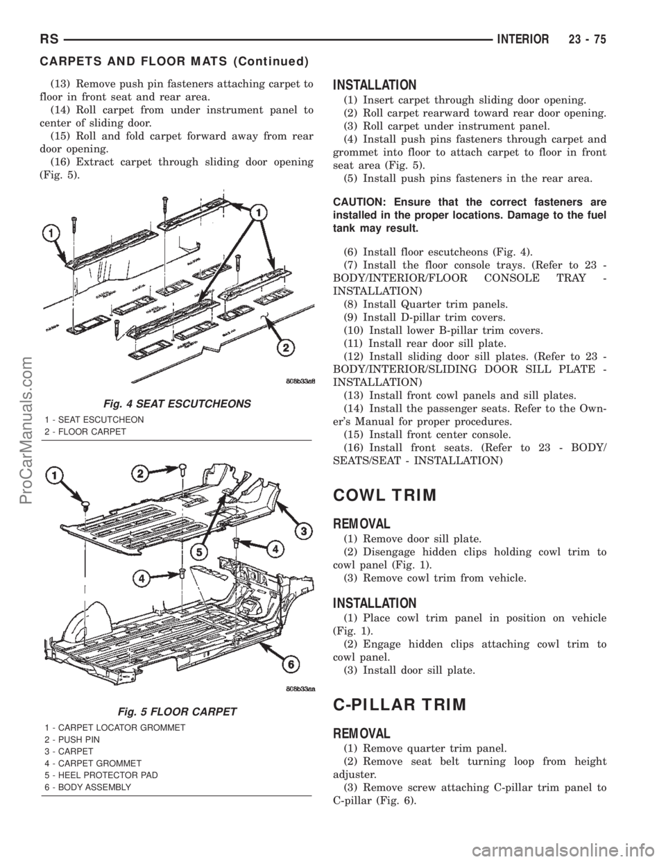
(13) Remove push pin fasteners attaching carpet to
floor in front seat and rear area.
(14) Roll carpet from under instrument panel to
center of sliding door.
(15) Roll and fold carpet forward away from rear
door opening.
(16) Extract carpet through sliding door opening
(Fig. 5).INSTALLATION
(1) Insert carpet through sliding door opening.
(2) Roll carpet rearward toward rear door opening.
(3) Roll carpet under instrument panel.
(4) Install push pins fasteners through carpet and
grommet into floor to attach carpet to floor in front
seat area (Fig. 5).
(5) Install push pins fasteners in the rear area.
CAUTION: Ensure that the correct fasteners are
installed in the proper locations. Damage to the fuel
tank may result.
(6) Install floor escutcheons (Fig. 4).
(7) Install the floor console trays. (Refer to 23 -
BODY/INTERIOR/FLOOR CONSOLE TRAY -
INSTALLATION)
(8) Install Quarter trim panels.
(9) Install D-pillar trim covers.
(10) Install lower B-pillar trim covers.
(11) Install rear door sill plate.
(12) Install sliding door sill plates. (Refer to 23 -
BODY/INTERIOR/SLIDING DOOR SILL PLATE -
INSTALLATION)
(13) Install front cowl panels and sill plates.
(14) Install the passenger seats. Refer to the Own-
er's Manual for proper procedures.
(15) Install front center console.
(16) Install front seats. (Refer to 23 - BODY/
SEATS/SEAT - INSTALLATION)
COWL TRIM
REMOVAL
(1) Remove door sill plate.
(2) Disengage hidden clips holding cowl trim to
cowl panel (Fig. 1).
(3) Remove cowl trim from vehicle.
INSTALLATION
(1) Place cowl trim panel in position on vehicle
(Fig. 1).
(2) Engage hidden clips attaching cowl trim to
cowl panel.
(3) Install door sill plate.
C-PILLAR TRIM
REMOVAL
(1) Remove quarter trim panel.
(2) Remove seat belt turning loop from height
adjuster.
(3) Remove screw attaching C-pillar trim panel to
C-pillar (Fig. 6).
Fig. 4 SEAT ESCUTCHEONS
1 - SEAT ESCUTCHEON
2 - FLOOR CARPET
Fig. 5 FLOOR CARPET
1 - CARPET LOCATOR GROMMET
2 - PUSH PIN
3 - CARPET
4 - CARPET GROMMET
5 - HEEL PROTECTOR PAD
6 - BODY ASSEMBLY
RSINTERIOR23-75
CARPETS AND FLOOR MATS (Continued)
ProCarManuals.com