2002 CHRYSLER TOWN AND COUNTRY center console install
[x] Cancel search: center console installPage 526 of 2399

LAMPS/LIGHTING - INTERIOR
TABLE OF CONTENTS
page page
LAMPS/LIGHTING - INTERIOR
SPECIFICATIONS
INTERIOR LAMPS.....................25
CENTER CONSOLE LAMP SWITCH
REMOVAL.............................26
INSTALLATION.........................26
CLUSTER ILLUMINATION LAMPS
REMOVAL.............................26
INSTALLATION.........................26
COURTESY LAMP
REMOVAL.............................26
INSTALLATION.........................26
DOME LAMP
REMOVAL.............................26INSTALLATION.........................26
GLOVE BOX LAMP SWITCH
REMOVAL.............................26
INSTALLATION.........................27
LIFTGATE LAMP
REMOVAL.............................27
INSTALLATION.........................27
READING LAMP
REMOVAL.............................27
INSTALLATION.........................28
VANITY LAMP
REMOVAL.............................28
INSTALLATION.........................28
LAMPS/LIGHTING - INTERIOR
SPECIFICATIONS
INTERIOR LAMPS
BULB APPLICATION TABLE
LAMP BULB
ABS LED
AIRBAG LED
ALARM SET PC74
AUTOSTICK VFD*
BRAKE SYSTEM WARNING LED
CONSOLE 194
CRUISE INDICATOR VFD*
DOME/RAIL LAMPS 578
DOOR AJAR INDICATOR LED
DOOR COURTESY LAMP 578
FRONT DOOR COURTESY 567
GLOVE BOX 194
HIGH BEAM INDICATOR (BASE
CLUSTER)LED
HIGH BEAM INDICATOR PC74
CLUSTER ILLUMINATION PC74
LAMP BULB
LIFTGATE 578
LIFTGATE AJAR LED
LOW FUEL INDICATOR LED
LOW WASHER FLUID
INDICATORLED
MIL (BASE CLUSTER) LED
MIL PC74
OIL INDICATOR (BASE
CLUSTER)LED
OIL INDICATOR PC74
OVERHEAD CONSOLE READING PC579
OVERDRIVE OFF INDICATOR VFD*
READING 578
SEAT BELT INDICATOR LED
TEMPERATURE INDICATOR LED
TRAC OFF INDICATOR VFD*
TURN SIGNAL INDICATOR
(BASE CLUSTER)LED
TURN SIGNAL INDICATOR PC74
VISOR VANITY 6501966
VOLTAGE INDICATOR LED
* VFD = VACUUM FLUORESCENT DISPLAY
RSLAMPS/LIGHTING - INTERIOR8L-25
ProCarManuals.com
Page 527 of 2399

CENTER CONSOLE LAMP
SWITCH
REMOVAL
(1)Disconnect and isolate the battery negative cable.
(2) Open console lid and remove tray.
(3) Using a flat bladed tool, pry up on the switch.
(4) Remove bulb from switch.
INSTALLATION
(1) Install bulb into switch.
(2) Push switch into console opening.
(3) Install tray and close lid.
(4) Connect battery negative cable.
CLUSTER ILLUMINATION
LAMPS
REMOVAL
(1) Remove the Instrument Cluster. Refer to Elec-
trical, Instrument Cluster, Removal.
(2) Turn over cluster and expose the illumination
bulb sockets.
(3) Identify which bulb is defective and twist it out
of the cluster using a counterclockwise motion.
INSTALLATION
(1) Install the new bulb socket into the cluster
using a clockwise motion.
(2) Install the Instrument Cluster. Refer to Electri-
cal, Instrument Cluster, Installation.
COURTESY LAMP
REMOVAL
(1)Disconnect and isolate the battery negative cable.
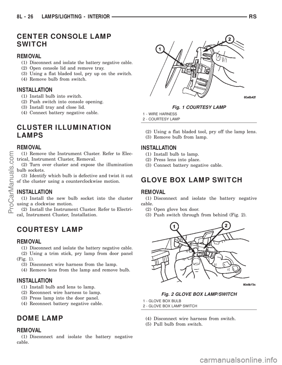
(2) Using a trim stick, pry lamp from door panel
(Fig. 1).
(3) Disconnect wire harness from the lamp.
(4) Remove lens from the lamp and remove bulb.
INSTALLATION
(1) Install bulb and lens to lamp.
(2) Reconnect wire harness to lamp.
(3) Press lamp into the door panel.
(4) Reconnect battery negative cable.
DOME LAMP
REMOVAL
(1) Disconnect and isolate the battery negative
cable.(2) Using a flat bladed tool, pry off the lamp lens.
(3) Remove bulb from lamp.
INSTALLATION
(1) Install bulb to lamp.
(2) Press lens into place.
(3) Connect battery negative cable.
GLOVE BOX LAMP SWITCH
REMOVAL
(1) Disconnect and isolate the battery negative
cable.
(2) Open glove box door.
(3) Push switch through from behind (Fig. 2).
(4) Disconnect wire harness from switch.
(5) Pull bulb from switch.
Fig. 1 COURTESY LAMP
1 - WIRE HARNESS
2 - COURTESY LAMP
Fig. 2 GLOVE BOX LAMP/SWITCH
1 - GLOVE BOX BULB
2 - GLOVE BOX LAMP SWITCH
8L - 26 LAMPS/LIGHTING - INTERIORRS
ProCarManuals.com
Page 530 of 2399

MESSAGE SYSTEMS
TABLE OF CONTENTS
page page
OVERHEAD CONSOLE
DESCRIPTION..........................1
OPERATION............................2
DIAGNOSIS AND TESTING - OVERHEAD
CONSOLE............................2
STANDARD PROCEDURE
STANDARD PROCEDURE - READING/
COURTESY LAMP REPLACEMENT.........3
STANDARD PROCEDURE - COMPASS
CALIBRATION.........................3
STANDARD PROCEDURE - COMPASS
DEMAGNETIZING......................4
STANDARD PROCEDURE - COMPASS
VARIATION ADJUSTMENT................4
REMOVAL - OVERHEAD CONSOLE..........5
INSTALLATION..........................5
ELECTRONIC VEHICLE INFO CENTER
DESCRIPTION..........................6
OPERATION............................6
DIAGNOSIS AND TESTING - ELECTRONIC
VEHICLE INFORMATION CENTER.........6
STANDARD PROCEDURE - ELECTRONIC
VEHICLE INFORMATION CENTER
PROGRAMMING.......................7REMOVAL.............................8
INSTALLATION..........................8
COMPASS/MINI-TRIP COMPUTER
DESCRIPTION..........................9
OPERATION............................9
DIAGNOSIS AND TESTING - COMPASS
MINI-TRIP COMPUTER..................9
REMOVAL.............................9
INSTALLATION..........................9
UNIVERSAL TRANSMITTER
DESCRIPTION..........................9
OPERATION...........................10
DIAGNOSIS AND TESTING - UNIVERSAL
TRANSMITTER.......................10
AMBIENT TEMP SENSOR
DESCRIPTION.........................10
OPERATION...........................10
DIAGNOSIS AND TESTING
DIAGNOSIS AND TESTING - AMBIENT
TEMPERATURE SENSOR...............11
DIAGNOSIS AND TESTING - AMBIENT
TEMPERATURE SENSOR CIRCUIT........11
REMOVAL.............................11
INSTALLATION.........................11
OVERHEAD CONSOLE
DESCRIPTION
Three overhead consoles are available on RS/RG
models. These are the Electronic Vehicle Information
Center (EVIC), Compass Mini-Trip Computer
(CMTC) or a Compass Temperature Computer (CT).
All consoles are equipped with two reading/courtesy
lamps and if the vehicle is equipped with a power
liftgate or power sliding door(s) the overhead console
will also include command switches for these fea-
tures. The overhead console is mounted with one
screw and two snap clips to a molded plastic retainer
bracket located above the headliner.
DESCRIPTION - COMPASS
All the available overhead consoles on this model
include Compass information. While in the compass/
temperature mode, the compass will display the
direction in which the vehicle is pointed using the
eight major compass headings (Examples: north is N,
northeast is NE). The self-calibrating compass unit
requires no adjusting in normal use. The only cali-bration that may prove necessary is to drive the vehi-
cle in three complete circles at 5 to 8 kilometers-per-
hour (3 to 5 miles-per-hour), on level ground, in not
less than forty-eight seconds. This will reorient the
compass unit to its vehicle.
The compass unit also will compensate for magne-
tism the body of the vehicle may acquire during nor-
mal use. However, avoid placing anything magnetic
directly on the roof of the vehicle. Magnetic mounts
for an antenna, a repair order hat, or a funeral pro-
cession flag can exceed the compensating ability of
the compass unit if placed on the roof panel. Mag-
netic bit drivers used on the fasteners that hold the
overhead console assembly to the roof header can
also affect compass operation. If the vehicle roof
should become magnetized, the demagnetizing and
calibration procedures found in this section may be
required to restore proper compass operation.
DESCRIPTION - TEMPERATURE
All the available overhead consoles on this model
include Temperature information. The temperature
displays the outside ambient temperature in whole
degrees. The temperature display can be toggled
RSMESSAGE SYSTEMS8M-1
ProCarManuals.com
Page 532 of 2399

ure. The electronics module is faulty and must be
replaced.
c.Failed J1850 Communication (EVIC only),
BUS (CT, CMTC)- The electronics module is not
receiving proper message input through the J1850
PCI data bus circuit. This can result from one or
more faulty electronic modules in the vehicle, or from
a faulty PCI data bus. The use of a DRB IIItscan
tool and the proper Diagnostic Procedures manual
are required for further diagnosis.
NOTE: If the compass functions, but accuracy is
suspect, it may be necessary to perform a variation
adjustment. This procedure allows the compass
unit to accommodate variations in the earth's mag-
netic field strength, based on geographic location.
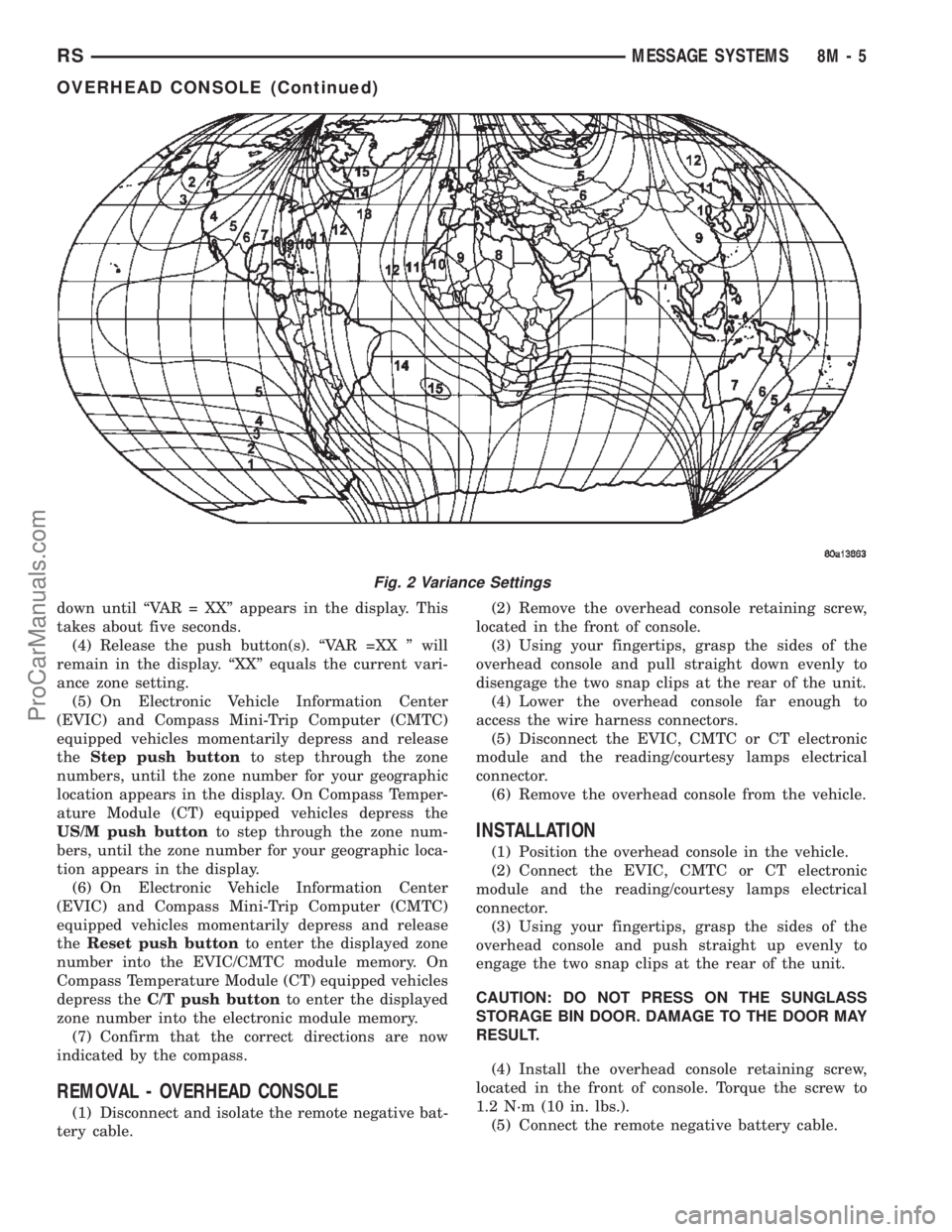
Refer to Compass Variation Adjustment in the Ser-
vice Procedures section of this group.
NOTE: If the compass reading displays dashes, and
only ªCALº appears in the display, demagnetizing
may be necessary to remove excessive residual
magnetic fields from the vehicle. Refer to Compass
Demagnetizing in the Service Procedures section of
this group.
STANDARD PROCEDURE
STANDARD PROCEDURE - READING/
COURTESY LAMP REPLACEMENT
(1) Open hood, disconnect and isolate the negative
battery cable remote terminal from the remote bat-
tery post.
(2) Remove the reading/courtesy lamp lens. Using
a trim stick, gently pry the forward edge of the read-
ing/courtesy lamp lens outward.
(3) Remove the reading/courtesy lamp socket from
the overhead console. Rotate the reading/courtesy
lamp socket one quarter turn counter clockwise.
(4) Remove the lamp and socket assembly.
(5) Reverse the above procedure to install.
STANDARD PROCEDURE - COMPASS
CALIBRATION
CAUTION: Do not place any external magnets, such
as magnetic roof mount antennas, in the vicinity of
the compass. Do not use magnetic tools when ser-
vicing the overhead console.
The electronic compass unit features a self-cali-
brating design, which simplifies the calibration pro-
cedure. This feature automatically updates the
compass calibration while the vehicle is being driven.This allows the compass unit to compensate for small
changes in the residual magnetism that the vehicle
may acquire during normal use. If the compass read-
ings appear to be erratic or out of calibration, per-
form the following calibration procedure. Also, new
service replacement Electronic Modules (EVIC,
CMTC, CT) must have their compass calibrated
using this procedure. Do not attempt to calibrate the
compass near large metal objects such as other vehi-
cles, large buildings, or bridges; or, near overhead or
underground power lines.
NOTE: Whenever the compass is calibrated manu-
ally, the variance number must also be reset. Refer
to Compass Variation Adjustment in this group.
Calibrate the compass manually as follows:
(1) Turn the ignition switch to the On position. If
the compass/thermometer data is not currently being
displayed, momentarily depress and release the C/T
push button to reach the compass/thermometer dis-
play.
(2) On Electronic Vehicle Information Center
(EVIC) and Compass Mini-Trip Computer (CMTC)
equipped vehicles depress the Reset push button and
hold the button down until ªCALº appears in the dis-
play. This takes about ten seconds, and appears
about five seconds after ªVAR = XXº is displayed. On
Compass Temperature Module (CT) equipped vehicles
depress the C/T push button and US/M push button
down until ªCALº appears in the display. This takes
about ten seconds, and appears about five seconds
after ªVAR = XXº is displayed.
(3) Release the push button(s).
(4) Drive the vehicle on a level surface, away from
large metal objects and power lines, through three or
more complete circles at between five and eight kilo-
meters-per-hour (three and five miles-per-hour) in
not less than 48 seconds. The ªCALº message will
disappear from the display to indicate that the com-
pass is now calibrated.
NOTE: If the ªCALº message remains in the display,
either there is excessive magnetism near the com-
pass, or the unit is faulty. Repeat the calibration
procedure one more time.
NOTE: If the wrong direction is still indicated in the
compass display, the area selected for calibration
may be too close to a strong magnetic field. Repeat
the calibration procedure in another location.
RSMESSAGE SYSTEMS8M-3
OVERHEAD CONSOLE (Continued)
ProCarManuals.com
Page 534 of 2399

down until ªVAR = XXº appears in the display. This
takes about five seconds.
(4) Release the push button(s). ªVAR =XX º will
remain in the display. ªXXº equals the current vari-
ance zone setting.
(5) On Electronic Vehicle Information Center
(EVIC) and Compass Mini-Trip Computer (CMTC)
equipped vehicles momentarily depress and release
theStep push buttonto step through the zone
numbers, until the zone number for your geographic
location appears in the display. On Compass Temper-
ature Module (CT) equipped vehicles depress the
US/M push buttonto step through the zone num-
bers, until the zone number for your geographic loca-
tion appears in the display.
(6) On Electronic Vehicle Information Center
(EVIC) and Compass Mini-Trip Computer (CMTC)
equipped vehicles momentarily depress and release
theReset push buttonto enter the displayed zone
number into the EVIC/CMTC module memory. On
Compass Temperature Module (CT) equipped vehicles
depress theC/T push buttonto enter the displayed
zone number into the electronic module memory.
(7) Confirm that the correct directions are now
indicated by the compass.
REMOVAL - OVERHEAD CONSOLE
(1) Disconnect and isolate the remote negative bat-
tery cable.(2) Remove the overhead console retaining screw,
located in the front of console.
(3) Using your fingertips, grasp the sides of the
overhead console and pull straight down evenly to
disengage the two snap clips at the rear of the unit.
(4) Lower the overhead console far enough to
access the wire harness connectors.
(5) Disconnect the EVIC, CMTC or CT electronic
module and the reading/courtesy lamps electrical
connector.
(6) Remove the overhead console from the vehicle.
INSTALLATION
(1) Position the overhead console in the vehicle.
(2) Connect the EVIC, CMTC or CT electronic
module and the reading/courtesy lamps electrical
connector.
(3) Using your fingertips, grasp the sides of the
overhead console and push straight up evenly to
engage the two snap clips at the rear of the unit.
CAUTION: DO NOT PRESS ON THE SUNGLASS
STORAGE BIN DOOR. DAMAGE TO THE DOOR MAY
RESULT.
(4) Install the overhead console retaining screw,
located in the front of console. Torque the screw to
1.2 N´m (10 in. lbs.).
(5) Connect the remote negative battery cable.
Fig. 2 Variance Settings
RSMESSAGE SYSTEMS8M-5
OVERHEAD CONSOLE (Continued)
ProCarManuals.com
Page 537 of 2399

driver door unlocks when the Unlock button of the
Remote Keyless Entry (RKE) transmitter is
depressed once. The Unlock button of the RKE trans-
mitter must be depressed twice to unlock all doors.
When All Doors is selected, all doors unlock when the
Unlock button of the RKE transmitter is depressed
once.
²REMOTE LINKED TO MEMORY?- This pro-
grammable feature only applies to vehicles equipped
with the optional memory / heated system. The
options include Yes and No. The default is No. When
Yes is selected, the memory system will recall the
Driver 1 or Driver 2 memory settings assigned to the
RKE transmitter being used to unlock the vehicle.
When No is selected, the memory system will only
recall memory settings when the Driver 1 or Driver 2
push buttons of the memory switch on the driver side
front door trim panel are depressed.
²SOUND HORN ON LOCK?- The options
include Yes and No. The default is No. When Yes is
selected, a short horn chirp will provide an audible
confirmation when the RKE receiver recognizes a
valid Lock signal from an RKE transmitter. When No
is selected, no horn chirp will occur with the RKE
Lock event. This feature may be selected indepen-
dent of theFLASH LIGHTS WITH LOCKS?pro-
grammable feature.
²FLASH LIGHTS WITH LOCKS?- The options
include Yes and No. The default is Yes. When Yes is
selected, a single flash of the hazard warning lamps
will provide an optical confirmation when the RKE
receiver recognizes a valid Lock signal from an RKE
transmitter, and two flashes of the same lamps will
occur when the RKE receiver recognizes a valid
Unlock signal from an RKE transmitter. When No is
selected, no lamp flash will occur with the RKE Lock
or Unlock event. This feature may be selected inde-
pendent of theSOUND HORN ON LOCK?pro-
grammable feature.
²HEADLAMP DELAY =- The options include
Off, 30 Sec, 60 Sec, and 90 Sec. The default is 90 Sec.
When a time interval is selected, the headlamps will
remain on for that length of time when the head-
lamps are turned off after the ignition is turned off,
or if the Auto mode is selected on vehicles with the
Auto Headlamps option. When Off is selected, the
headlamp delay feature is disabled.
²HEADLAMPS ON WITH WIPERS?- This pro-
grammable feature only applies to vehicles equipped
with the optional Auto Headlamps. The options
include Yes and No. The default is No. When Yes is
selected, the headlamps will turn on automatically
when the windshield wipers are turned on. The head-
lamps will turn off when the wipers are turned off,
as long as the headlamp switch is in the Auto or Off
positions. When No is selected, the headlamps willonly turn on if manually selected or if the Auto mode
is selected and the outside ambient light levels dic-
tate that they should be on.
²RETRAIN TIRE SENSORS?- This program-
mable feature only applies to vehicles equipped with
the optional Tire Pressure Monitoring System. The
options include Yes and No. The default is No. When
Yes is selected, and the menu button is depressed the
EVIC will enter the training mode, starting with the
left front tire.
²POWER ACCESSORY DELAY?- The options
include Yes and No. The default is Yes. When No is
selected, the accessory powered components will turn
off automatically when the ignition key is turned off.
When Yes is selected, the accessory powered compo-
nents will remain on for 45 seconds when the igni-
tion key is turned off.
REMOVAL
(1) Disconnect and isolate the battery negative
cable.
(2) Remove overhead console. Refer to Overhead
Console Removal and Installation in this section(Re-
fer to 8 - ELECTRICAL/OVERHEAD CONSOLE -
REMOVAL).
(3) Remove the ten screws holding the EVIC mod-
ule in the overhead console.
(4) Remove EVIC module from console assembly.
NOTE: IF THE EVIC MODULE IS BEING REPLACED
THE TIRE PRESSURE MONITORING SYSTEM (if
equipped) MUST BE RETRAINED. REFER TO THE
TIRES/WHEELS SECTION OF THIS MANUAL FOR
DETAILED INSTRUCTIONS.
INSTALLATION
(1) Position the EVIC module in the overhead con-
sole.
(2) Install the ten screws holding the EVIC module
in the overhead console.
(3) Install the overhead console (Refer to 8 -
ELECTRICAL/OVERHEAD CONSOLE - INSTALLA-
TION).
(4) Connect the battery negative cable.
NOTE: IF THE EVIC MODULE IS BEING REPLACED
THE TIRE PRESSURE MONITORING SYSTEM (if
equipped) MUST BE RETRAINED. REFER TO THE
TIRES/WHEELS SECTION OF THIS MANUAL FOR
DETAILED INSTRUCTIONS.
8M - 8 MESSAGE SYSTEMSRS
ELECTRONIC VEHICLE INFO CENTER (Continued)
ProCarManuals.com
Page 538 of 2399

NOTE: IF A NEW EVIC MODULE HAS BEEN
INSTALLED, THE COMPASS WILL HAVE TO BE
CALIBRATED AND THE VARIANCE SET. REFER TO
COMPASS VARIATION ADJUSTMENT AND COM-
PASS CALIBRATION IN THE SERVICE PROCE-
DURES SECTION OF THIS GROUP FOR THE
PROCEDURES.
COMPASS/MINI-TRIP
COMPUTER
DESCRIPTION
The Compass Mini-Trip Computer (CMTC) and
Compass Temperature (CT) computer are modules
located in the overhead console. Vehicles are
equipped with either the CMTC or the CT computers
not both. The CMTC is different in the fact that it is
equipped with the mini-trip feature. The CMTC, CT
consists of a electronic control module with a vacuum
fluorescent display (VFD) and function switches. The
CMTC, CT consists of a electronic module that dis-
plays compass, trip computer (CMTC only), and tem-
perature features. Actuating the STEP push button
(CMTC only) will cause the CMTC to change mode of
operation when ignition is ON. Actuating the STEP
push button (CMTC only) will cause the CMTC to
change mode of operation when ignition is ON.
Example:
²Average miles per gallon (ECO)
²Distance to empty (DTE)
²Instant miles per gallon (ECO)
²Trip odometer (ODO)
²Elapsed time (ET)
²Off
Actuating the C/T push button will cause the
CMTC, CT to change to Compass/Temperature dis-
play.
OPERATION
The Compass Mini-Trip Computer (CMTC), Com-
pass Temperature (CT) module in the overhead con-
sole has buttons used to select various functions. The
CMTC, CT selector buttons will not operate until the
ignition is in the RUN position.
When the ignition switch is first turned to the
RUN position the CMTC, CT display;
²Blanks momentarily
²All segments of the VFD will light for one sec-
ond
²Blanks momentarily
²Returns to the last mode setting selected before
the ignition was last switched OFF.
DIAGNOSIS AND TESTING - COMPASS
MINI-TRIP COMPUTER
Compass Mini-Trip Computer (CMTC) and Com-
pass Temperature (CT) data is obtained from the
Body Control Module (BCM) on the J1850 Data Bus
circuit. The CMTC and CT will display dashes (- -)
for any of the screens it did not receive the bus mes-
sages. The label corresponding to the missing infor-
mation will be lit. If no compass mini-trip computer
data is displayed, check the J1850 Data Bus circuit
communications and the BCM. If the brightness level
is improper check the J1850 Data Bus circuit.
The DRB IIItis recommended for checking the
J1850 Data Bus circuit and the BCM. Perform the
CMTC, CT self diagnosis before replacing the CMTC
or CT module.
REMOVAL
(1) Disconnect and isolate the battery negative
cable.
(2) Remove overhead console. Refer to Overhead
Console Removal and Installation in this section(Re-
fer to 8 - ELECTRICAL/OVERHEAD CONSOLE -
REMOVAL).
(3) Remove the screws holding Compass Mini-Trip
Computer module in the overhead console.
(4) Remove CMTC module from console assembly.
INSTALLATION
(1) Position the compass mini-trip computer mod-
ule in the overhead console.
(2) Install the ten screws holding the compass
mini-trip computer module in the overhead console.
(3) Install the overhead console. Refer to Overhead
Console Removal and Installation in this section.
(4) Connect the battery negative cable.
NOTE: If a new module has been installed, the com-
pass will have to be calibrated and the variance set.
Refer to Compass Variation Adjustment and Com-
pass Calibration in the Service Procedures section
of this group for the procedures.
UNIVERSAL TRANSMITTER
DESCRIPTION
On some RS models a Universal Transmitter trans-
ceiver is standard factory-installed equipment. The
universal transmitter transceiver is integral to the
Electronic Vehicle Information Center (EVIC) and the
Compass Mini-Trip Computer (CMTC), which is
located in the overhead console. The only visible com-
ponent of the universal transmitter are the three
transmitter push buttons centered between the mod-
RSMESSAGE SYSTEMS8M-9
ELECTRONIC VEHICLE INFO CENTER (Continued)
ProCarManuals.com
Page 559 of 2399

POWER SLIDING DOOR SYSTEM
TABLE OF CONTENTS
page page
POWER SLIDING DOOR SYSTEM
DESCRIPTION.........................18
OPERATION...........................20
DIAGNOSIS AND TESTING - POWER SLIDING
DOOR SYSTEM.......................21
STANDARD PROCEDURE
STANDARD PROCEDURE - WELLNUT
REPLACEMENT.......................27
STANDARD PROCEDURE - POWER DOOR
LEARN CYCLE.......................27
STANDARD PROCEDURE - SLIDING DOOR
ADJUSTMENT........................27
LATCH
DESCRIPTION.........................28
OPERATION...........................28
REMOVAL.............................28
INSTALLATION.........................29
SLIDING DOOR MOTOR
DESCRIPTION.........................29
OPERATION...........................29
REMOVAL.............................29
INSTALLATION.........................30
FULL OPEN SWITCH
DESCRIPTION.........................30
OPERATION...........................30
LEFT B-PILLAR SWITCH
DESCRIPTION.........................31
OPERATION...........................31
REMOVAL.............................31
INSTALLATION.........................31RIGHT B-PILLAR SWITCH
DESCRIPTION.........................31
OPERATION...........................31
REMOVAL.............................31
INSTALLATION.........................31
LOWER DRIVE UNIT
DESCRIPTION.........................31
OPERATION...........................31
REMOVAL.............................32
INSTALLATION.........................32
LOWER DRIVE UNIT TRACK & RACK
DESCRIPTION.........................33
OPERATION...........................33
REMOVAL.............................33
INSTALLATION.........................33
WIRING HARNESS
DESCRIPTION.........................34
OPERATION...........................34
REMOVAL.............................34
INSTALLATION.........................35
FLEX DRIVE
DESCRIPTION.........................35
OPERATION...........................36
REMOVAL.............................36
INSTALLATION.........................36
SLIDING DOOR MODULE
DESCRIPTION.........................37
OPERATION...........................37
REMOVAL.............................38
INSTALLATION.........................38
POWER SLIDING DOOR
SYSTEM
DESCRIPTION
Some vehicles are equipped with a power opening
and closing sliding door system (Fig. 1). Depending
on how the vehicle is ordered it may be equipped
with only a right side power door or right and left
side power doors. This power sliding door system is a
complex system consisting of many components.
Some of these components are the door motor, latch
assembly, sliding door control module, lower drive
unit, flex drive assembly, wire harness and track,
lower drive unit track and rack assembly, full open
switch, B-pillar switch, overhead console switch, key
fob switches (Fig. 2), pawl switch, ratchet switch and
child lockout and handle switches.Each power side door has its own door control mod-
ule, located in the center of the door behind the door
trim panel. (Refer to 8 - ELECTRICAL/ELEC-
TRONIC CONTROL MODULES/DOOR CONTROL
MODULE - DESCRIPTION) The power side door
motor is located in the front portion of the door, on
the inner door panel sheet metal. The latch assembly
is located in the rear of the power side door, near the
body line. The lower drive unit is attached to the
lower door hinge. The flex drive assembly connects
the door motor to the lower drive unit. The wire har-
ness and track and the lower drive unit track are vis-
ible with the door open in the lower door sill area.
The power side door full open switch is located under
the lower drive unit and is part of the hold open
latch assembly. The pawl, ratchet, handle and child
lockout switches are all located on the power side
door latch assembly. The B-pillar switch, as it will be
8N - 18 POWER SLIDING DOOR SYSTEMRS
ProCarManuals.com