2002 CHRYSLER TOWN AND COUNTRY front shroud
[x] Cancel search: front shroudPage 215 of 2399

DESCRIPTION - ELECTRONIC VARIABLE
BRAKE PROPORTIONING
Vehicles equipped with ABS use electronic variable
brake proportioning (EVBP) to balance front-to-rear
braking. The EVBP is used in place of a rear propor-
tioning valve. The EVBP system uses the ABS sys-
tem to control the slip of the rear wheels in partial
braking range. The braking force of the rear wheels
is controlled electronically by using the inlet and out-
let valves located in the integrated control unit
(ICU).
DESCRIPTION - TRACTION CONTROL SYSTEM
Traction control reduces wheel slip and maintains
traction at the driving wheels at speeds below 56
km/h (35 mph) when road surfaces are slippery. The
traction control system reduces wheel slip by braking
the wheel that is losing traction.
HYDRAULIC SHUTTLE VALVES
Two pressure relief hydraulic shuttle valves are
included on vehicles with traction control. These
valves are located inside the HCU and cannot be ser-
viced separately from the HCU.
TRACTION CONTROL LAMP
The traction control function lamp is located in the
transmission range indicator display of the instru-
ment cluster, displaying TRAC, TRAC OFF or nei-
ther depending on system mode.
The TRAC OFF lamp is controlled by a Traction
Control Off switch that is a momentary contact type
switch. The Traction Control Off switch is located on
the steering column upper shroud.
OPERATION
OPERATION - ANTILOCK BRAKE SYSTEM
There are a few performance characteristics of the
Mark 20e Antilock Brake System that may at first
seem abnormal, but in fact are normal. These char-
acteristics are described below.
NORMAL BRAKING
Under normal braking conditions, the ABS func-
tions the same as a standard base brake system with
a diagonally split master cylinder and conventional
vacuum assist.
ABS BRAKING
ABS operation is available at all vehicle speeds
above 3±5 mph. If a wheel locking tendency is
detected during a brake application, the brake sys-
tem enters the ABS mode. During ABS braking,
hydraulic pressure in the four wheel circuits is mod-ulated to prevent any wheel from locking. Each
wheel circuit is designed with a set of electric sole-
noids to allow modulation, although for vehicle sta-
bility, both rear wheel solenoids receive the same
electrical signal. Wheel lockup may be perceived at
the very end of an ABS stop and is considered nor-
mal.
During an ABS stop, the brakes hydraulic system
is still diagonally split. However, the brake system
pressure is further split into three control channels.
During antilock operation of the vehicle's brake sys-
tem, the front wheels are controlled independently
and are on two separate control channels, and the
rear wheels of the vehicle are controlled together.
The system can build and release pressure at each
wheel, depending on signals generated by the wheel
speed sensors (WSS) at each wheel and received at
the controller antilock brake (CAB).
NOISE AND BRAKE PEDAL FEEL
During ABS braking, some brake pedal movement
may be felt. In addition, ABS braking will create
ticking, popping, or groaning noises heard by the
driver. This is normal and is due to pressurized fluid
being transferred between the master cylinder and
the brakes. If ABS operation occurs during hard
braking, some pulsation may be felt in the vehicle
body due to fore and aft movement of the suspension
as brake pressures are modulated.
At the end of an ABS stop, ABS is turned off when
the vehicle is slowed to a speed of 3±4 mph. There
may be a slight brake pedal drop anytime that the
ABS is deactivated, such as at the end of the stop
when the vehicle speed is less than 3 mph or during
an ABS stop where ABS is no longer required. These
conditions exist when a vehicle is being stopped on a
road surface with patches of ice, loose gravel, or sand
on it. Also, stopping a vehicle on a bumpy road sur-
face activates ABS because of the wheel hop caused
by the bumps.
TIRE NOISE AND MARKS
Although the ABS system prevents complete wheel
lockup, some wheel slip is desired in order to achieve
optimum braking performance. Wheel slip is defined
as follows: 0 percent slip means the wheel is rolling
freely and 100 percent slip means the wheel is fully
locked. During brake pressure modulation, wheel slip
is allowed to reach up to 25±30 percent. This means
that the wheel rolling velocity is 25±30 percent less
than that of a free rolling wheel at a given vehicle
speed. This slip may result in some tire chirping,
depending on the road surface. This sound should not
be interpreted as total wheel lockup.
Complete wheel lockup normally leaves black tire
marks on dry pavement. The ABS will not leave dark
5 - 86 BRAKES - ABSRS
BRAKES - ABS (Continued)
ProCarManuals.com
Page 221 of 2399

(2) Install wheel speed sensor head into rear of
hub and bearing aligning index tab with the notch in
the top of the mounting hole. Push the sensor in
until it snaps into place on the metal retaining clip.
(3) Install secondary (yellow) retaining clip over
wheel speed sensor head and engage the tabs on each
side.
(4) Route sensor cable under leaf spring along rear
of axle. Install speed sensor cable into routing clips
on rear brake flex hose (Fig. 3).
(5) Install cable into metal routing clip and attach
it to the rear axle with mounting bolt (Fig. 3).
Tighten mounting bolt to 16 N´m (140 in. lbs.).
(6) Connect wheel speed sensor cable to vehicle
wiring harness (Fig. 2).Be sure speed sensor
cable connector is fully seated and locked into
vehicle wiring harness connector.
(7) Install speed sensor cable grommet into hole in
floor pan making sure grommet is fully seated into
hole.
(8) Lower vehicle.
(9) Road test vehicle to ensure proper operation of
the base and ABS braking systems.
TONE WHEEL
INSPECTION - TONE WHEEL
NOTE: Rear tone wheels for front-wheel-drive vehi-
cles are sealed within the hub and bearing assem-
bly and cannot be inspected or replaced.
Replacement of the hub and bearing is necessary.Tone wheels can cause erratic wheel speed sensor
signals. Inspect tone wheels for the following possible
causes.
²missing, chipped, or broken teeth
²contact with the wheel speed sensor
²wheel speed sensor to tone wheel alignment
²wheel speed sensor to tone wheel clearance
²excessive tone wheel runout
²tone wheel loose on its mounting surface
If a front tone wheel is found to need replacement,
the drive shaft must be replaced. No attempt should
be made to replace just the tone wheel. (Refer to 3 -
DIFFERENTIAL & DRIVELINE/HALF SHAFT -
REMOVAL)
If a rear tone wheel is found to need replacement
on an all-wheel-drive model, the drive shaft must be
replaced. No attempt should be made to replace just
the tone wheel. (Refer to 3 - DIFFERENTIAL &
DRIVELINE/HALF SHAFT - REMOVAL)
If wheel speed sensor to tone wheel contact is evi-
dent, determine the cause and correct it before
replacing the wheel speed sensor or tone wheel.
Check the gap between the speed sensor head and
the tone wheel to ensure it is within specifications.
(Refer to 5 - BRAKES - ABS/ELECTRICAL - SPEC-
IFICATIONS)
Excessive wheel speed sensor runout can cause
erratic wheel speed sensor signals. Refer to SPECI-
FICATIONS in this section of the service manual for
the maximum allowed tone wheel runout (Refer to 5 -
BRAKES - ABS/ELECTRICAL - SPECIFICATIONS).
If tone wheel runout is excessive, determine if it is
caused by a defect in the driveshaft assembly or hub
and bearing. Replace as necessary.
Tone wheels are pressed onto their mounting sur-
faces and should not rotate independently from the
mounting surface. Replacement of the front drive-
shaft, rear driveshaft (AWD only) or rear hub and
bearing is necessary.
TRACTION CONTROL SWITCH
DIAGNOSIS AND TESTING - TRACTION
CONTROL SWITCH
(1) Remove lower column shroud.
(2) Disconnect traction control switch harness from
column harness below column.
(3) Using an ohmmeter, check for continuity read-
ing between pins. Refer to TRACTION CONTROL
SWITCH CONTINUITY test table and (Fig. 5).
Fig. 4 SENSOR CONNECTION AT HUB AND
BEARING
1 - SECONDARY SENSOR RETAINING CLIP
2 - METAL SENSOR RETAINING CLIP
3 - HUB AND BEARING
5 - 92 BRAKES - ABSRS
REAR WHEEL SPEED SENSOR - FWD (Continued)
ProCarManuals.com
Page 612 of 2399
(6) Refer to the proper Body Diagnostic Procedures
manual if any diagnostic codes are found in Step 4 or
Step 5.
(7) Erase stored diagnostic codes if there are no
active diagnostic codes. If problems remain, diagnos-
tic codes will not erase. Refer to the Proper Body
Diagnostic Procedures Manual to diagnose the prob-
lem.If airbag warning lamp either fails to light,
or goes on and stays on, there is a system mal-
function. Refer to the proper Body Diagnostic
Procedures manual to diagnose the problem.
CLOCK SPRING
DESCRIPTION
The clock spring is screwed to a plastic mounting
platform on the steering column behind the steering
wheel. The clock spring is used to maintain a contin-
uous electrical circuit between the wiring harness
and the drivers airbag.
OPERATION
This assembly consists of a flat ribbon like electri-
cally conductive tape which winds and unwinds with
the steering wheel rotation. The clock spring cannot
be repaired. If the clock spring is faulty, damaged, or
if the airbag has been deployed, the clock spring
must be replaced.
STANDARD PROCEDURE - CLOCK SPRING
CENTERING
If the rotating tape (wire coil) in the clock spring is
not positioned properly with the steering wheel and
the front wheels, the clock spring may fail. The fol-
lowing procedure MUST BE USED to center the
clock spring if it is not known to be properly posi-
tioned, or if the front wheels were moved from the
straight ahead position.
(1) Adjust the steering wheel so that the tires are
in a straight ahead position.
(2) Remove Driver Airbag from steering wheel.
(3) Disconnect wire connectors from back of airbag.
(4) Remove steering wheel.
(5) Rotate the clock spring rotor clockwise until
the rotor stops. Do not apply excessive force.
(6) From the end of travel, rotate the rotor two
turns counterclockwise until the wires end up at the
top.
(7) Install steering wheel and airbag.
WARNING: DO NOT CONNECT THE BATTERY NEG-
ATIVE CABLE. REFER TO ELECTRICAL,
RESTRAINTS, DIAGNOSIS AND TESTING - AIRBAG
SYSTEM FIRST.
REMOVAL
(1) Position steering wheel and front wheels
straight ahead.
(2) Release hood latch and open hood. Disconnect
and isolate the battery negative cable.
(3) Remove driver airbag from steering wheel.
(4) Disconnect wire connectors from back of driver
airbag.
(5) Disconnect the 2±way connector from remote
radio control harness and the 4-way connector from
the speed control/horn harness.
(6) Remove steering wheel.
(7) Remove steering column shrouds.
(8) Disconnect 4-way and 6-way connectors
between the clock spring and the instrument panel
wiring harness.
(9) Remove clock spring from housing assembly by
removing the two retaining screws retaining the
clock spring.
INSTALLATION
(1) Position the clock spring into the housing.
Install the two retaining screws to clock spring.
(2) Connect the 4-way and 6-way harness between
the clock spring and the instrument panel.
(3) Install the steering wheel. Refer to Steering,
Column, Steering Wheel, Installation.
(4) Connect the harness connector to the driver
airbag.
(5) Connect the remote radio control harness and
the speed control/horn harness.
(6) Install the driver airbag into the steering
wheel.
(7) Install the steering column upper and lower
shrouds.
WARNING: DO NOT CONNECT THE BATTERY NEG-
ATIVE CABLE. REFER TO ELECTRICAL,
RESTRAINTS, DIAGNOSIS AND TESTING - AIRBAG
SYSTEM FIRST.
DRIVER AIRBAG
DESCRIPTION
The Driver Airbag is located in the center of the
steering wheel. The most visible part of the airbag is
the cover/horn switch.
OPERATION
The Driver Airbag cover contains the horn switch,
inflator device, and a fabric bag. The airbag cover/
horn switch is serviced separately from the inflator
and bag components.
RSRESTRAINTS8O-3
RESTRAINTS (Continued)
ProCarManuals.com
Page 613 of 2399
When the front airbag system is deployed, the fol-
lowingMUSTbe replaced:
²Complete Steering Column Assembly.
²Lower Steering Column Coupler.
²Steering Wheel.
²Clock Spring.
²Driver Airbag
²Passenger Airbag
²Upper Instrument Panel with Pad.
CARE OF UNDEPLOYED AIRBAGS
Airbags must be stored in their original special
container until used for service. At no time should a
source of electricity be permitted near the inflator on
the back of an airbag. When carrying or handling an
undeployed airbag, the trim side of the airbag should
be pointing away from the body to minimize possibil-
ity of injury if accidental deployment occurs. Do not
place undeployed airbag face down on a solid surface,
the airbag will propel into the air if accidental
deployment occurs.
STANDARD PROCEDURE - CLEAN UP
Roll or fold the driver airbag towards the steering
wheel and then tape the bag to the steering wheel.
Use a vacuum cleaner to remove any residual pow-
der from the vehicle interior. Work from the outside
in to avoid kneeling or sitting in a contaminated
area. Vacuum the heater and A/C outlets as well. If
HVAC was in RECIRC mode at time of airbag
deployment, operate HVAC blower on low speed/heat
and vacuum powder residue expelled from the heat
outlets. Multiple vacuum cleaning may be necessary
to decontaminate the interior of the vehicle.
REMOVAL
DEPLOYED AIRBAG
The Driver Airbag and Driver Airbag Cover/Horn
Pad are serviced separately from each other.
(1) Clean powder residue from interior of vehicle,
(Refer to 8 - ELECTRICAL/RESTRAINTS/DRIVER
AIRBAG - STANDARD PROCEDURE ) Cleanup.
(2) Remove two screws attaching Driver Airbag to
steering wheel.
(3) Remove the driver airbag from steering wheel.
(4) Disconnect wire connectors from Airbag and
Clock Spring.
(5) Adjust the steering wheel so that the tires are
in a straight ahead position. Remove steering wheel,
(Refer to 19 - STEERING/COLUMN/STEERING
WHEEL - REMOVAL)
(6) Disconnect the 2-way and 4-way connectors
between the clock spring and the instrument panel
wiring harness.(7) Remove upper and lower steering column
shrouds.
(8) Remove clock spring from the housing assem-
bly by depressing the 2 tabs on the clock spring.
UNDEPLOYED AIRBAG
(1) Remove screws attaching airbag/horn switch to
steering wheel.
(2) Remove Driver Airbag from steering wheel.
(3) Disconnect wire connectors from driver airbag
and clock spring.
INSTALLATION
DEPLOYED AIRBAG
(1) Perform cleanup procedure.(Refer to 8 - ELEC-
TRICAL/RESTRAINTS/DRIVER AIRBAG - STAN-
DARD PROCEDURE)
(2) Install a new steering column assembly and
lower steering column coupler. Refer to Steering, Col-
umn, Installation.
(3) Install the clock spring.
(4) Install the driver airbag and the two screws
retaining the airbag. Tighten screws to 10 N´m (90
in. lbs.)
WARNING: DO NOT CONNECT THE BATTERY NEG-
ATIVE CABLE. REFER TO ELECTRICAL,
RESTRAINTS, DIAGNOSIS AND TESTING - AIRBAG
SYSTEM FIRST.
UNDEPLOYED AIRBAG
(1) Position a new airbag into the airbag cavity.
(2) Install the two screws retaining the airbag.
Tighten screws to 10 N´m (90 in. lbs.)
WARNING: DO NOT CONNECT THE BATTERY NEG-
ATIVE CABLE. REFER TO ELECTRICAL,
RESTRAINTS, DIAGNOSIS AND TESTING - AIRBAG
SYSTEM FIRST.
DRIVER AIRBAG TRIM COVER
REMOVAL
The horn switch is integral to the driver airbag
trim cover. If either component is faulty or damaged,
the entire driver airbag trim cover and horn switch
unit must be replaced.
(1) Disconnect and isolate the battery negative
cable.
WARNING: WAIT TWO MINUTES FOR THE AIRBAG
SYSTEM RESERVE CAPACITOR TO DISCHARGE.
8O - 4 RESTRAINTSRS
DRIVER AIRBAG (Continued)
ProCarManuals.com
Page 1510 of 2399
CONDITION POSSIBLE CAUSES CORRECTION
11. Worn or binding seat and bearing
in front strut assembly.11. Replace seat and bearing in front strut
assembly.
STEERING WHEEL DOES
NOT RETURN TO
CENTER POSITION.1. Tires not inflated properly. 1. Inflate tires to specified pressure.
2. Improper front wheel alignment. 2. Check and adjust wheel alignment as
necessary.
3. Lack of lubrication causing binding
in front lower control arm ball joints.3. Lubricate ball joints if ball joints are not a
lubricated for life type of ball joint, then
inspect ball joint for wear, replace lower
control arm as necessary. If ball joint is a
lubricated for life ball joint, replace lower
control arm ball joint.
4. Steering column coupling joints
misaligned.4. Realign steering column coupling joints.
5. Steering wheel rubbing.** 5. Adjust steering column shrouds to
eliminate rubbing condition.
6. Damaged, mispositioned or
unlubricated steering column coupler
to dash seal.**6. Replace, reposition, or lubricate dash
seal.
7. Binding mount bearing in front
strut assembly.7. Replace mount bearing in front strut
assembly.
8. Binding shaft bearing in steering
column.8. Replace the steering column.
9. Excessive friction in steering
column coupling.9. Replace steering column coupling.
10. Excessive friction in power
steering gear.10. Replace power steering gear.
EXCESSIVE STEERING
WHEEL KICKBACK OR
TOO MUCH STEERING
WHEEL FREE PLAY.1. Air in the fluid of the power
steering system.1. Bleed air from system following the the
power steering pump initial operation
service procedure.*
2. Power steering gear loose on
cradle/crossmember.2. Inspect power steering gear mounting
bolts. Replace as necessary. Tighten to the
specified torque.
3. Steering column coupling or
intermediate shaft worn, broken or
loose.3. Replace steering column coupling or
intermediate shaft.
4. Free play in steering column. 4. Check all components of the steering
column and repair or replace as required.
5. Worn lower control arm ball joints. 5. Replace lower control arm ball joints as
required.
6. Loose steering knuckle-to-ball joint
stud pinch bolt.6. Inspect pinch bolt, replace as necessary,
and tighten to specified torque.
7. Front wheel bearing loose or
worn.7. Replace hub and bearing as necessary.
8. Loose outer tie rod end. 8. Replace outer tie rod end that has
excessive free play.
RSSTEERING19-7
STEERING (Continued)
ProCarManuals.com
Page 1515 of 2399
WARNING: THE AIR BAG SYSTEM IS A SENSITIVE,
COMPLEX ELECTRO-MECHANICAL UNIT. BEFORE
ATTEMPTING TO DIAGNOSE, REMOVE OR INSTALL
THE AIR BAG SYSTEM COMPONENTS YOU MUST
FIRST DISCONNECT AND ISOLATE THE BATTERY
NEGATIVE (GROUND) CABLE. THEN WAIT TWO
MINUTES FOR THE SYSTEM CAPACITOR TO DIS-
CHARGE. FAILURE TO DO SO COULD RESULT IN
ACCIDENTAL DEPLOYMENT OF THE AIR BAG AND
POSSIBLE PERSONAL INJURY. THE FASTENERS,
SCREWS, AND BOLTS, ORIGINALLY USED FOR
THE AIR BAG COMPONENTS, HAVE SPECIAL
COATINGS AND ARE SPECIFICALLY DESIGNED
FOR THE AIR BAG SYSTEM. THEY MUST NEVER
BE REPLACED WITH ANY SUBSTITUTES. ANYTIME
A NEW FASTENER IS NEEDED, REPLACE WITH
THE CORRECT FASTENERS PROVIDED IN THE
SERVICE PACKAGE OR FASTENERS LISTED IN
THE PARTS BOOKS.
WARNING: SAFETY GOGGLES SHOULD BE WORN
AT ALL TIMES WHEN WORKING ON STEERING
COLUMNS.
CAUTION: Disconnect negative (ground) cable from
the battery before servicing any column compo-
nent.
CAUTION: Do not attempt to remove the pivot pins
to disassemble the tilting mechanism. Damage will
occur.
DIAGNOSIS AND TESTING - STEERING
COLUMN
For diagnosis of conditions relating to the steering
column (Refer to 19 - STEERING - DIAGNOSIS ANDTESTING) and (Refer to 19 - STEERING - DIAGNO-
SIS AND TESTING).
REMOVAL
NOTE: Before proceeding, (Refer to 19 - STEERING/
COLUMN - WARNING).
(1) Make sure the front wheels of the vehicle are
in the STRAIGHT AHEAD position before beginning
the column removal procedure.
(2) Disconnect negative (ground) cable from the
battery and isolate cable from battery terminal.
(3) Remove the lower shroud (Refer to 19 -
STEERING/COLUMN/LOWER SHROUD - REMOV-
AL).
(4) Remove the traction off switch.
(5) Remove the upper shroud.
(6) Remove the cluster trim bezel (Refer to 23 -
BODY/INSTRUMENT PANEL/CLUSTER BEZEL -
REMOVAL).
(7) Remove the knee blocker (Refer to 23 - BODY/
INSTRUMENT PANEL/STEERING COLUMN
OPENING COVER - REMOVAL).
(8) Remove the parking brake handle link.
(9) Remove the knee blocker reinforcement (Refer
to 23 - BODY/INSTRUMENT PANEL/KNEE
BLOCKER - REMOVAL).
(10) Remove the airbag (Refer to 8 - ELECTRI-
CAL/RESTRAINTS/DRIVER AIRBAG - REMOVAL).
(11) Remove the steering wheel retaining nut.
(12) Remove the vibration damper weight.
(13) Remove the steering wheel (Refer to 19 -
STEERING/COLUMN/STEERING WHEEL -
REMOVAL). (Fig. 3)
(14) Disconnect the wiring harness connectors
from the clockspring, multi-function switch, halo
lamp, SKIM module, ignition switch and BTSI sole-
noid.
1 - CLOCKSPRING WIRING
2 - STEERING WHEEL
3 - UPPER SHROUD
4 - FIXED SHROUD
5 - SCREW
6 - STEERING COLUMN MOUNTING PLATE
7 - NUT
8 - DASH PANEL STEERING COLUMN MOUNTING BRACKET
9 - STUDS (4)
10 - STEERING COLUMN LOCKING PIN
11 - NUT/WASHER ASSEMBLY
12 - STEERING COLUMN ASSEMBLY
13 - LOWER SHROUD
14 - SCREWS
15 - STEERING WHEEL RETAINING NUT16 - STEERING WHEEL DAMPER
17 - CLOCKSPRING
18 - SCREW
19 - MULTI-FUNCTION SWITCH
20 - PINCH BOLT
21 - STEERING COLUMN COUPLER
22 - PINCH BOLT RETAINING PIN
23 - DASH PANEL
24 - SILENCER SHELL
25 - INTERMEDIATE SHAFT SHIELD AND SEAL
26 - INTERMEDIATE SHAFT
27 - ROLL PIN
28 - POWER STEERING GEAR
29 - FRONT SUSPENSION CRADLE/CROSSMEMBER
19 - 12 COLUMNRS
COLUMN (Continued)
ProCarManuals.com
Page 2048 of 2399
INSTALLATION
(1) Install the glove box latch striker.
(2) Install the screws holding latch striker to
instrument panel.
(3) Close glove box door.
INSTRUMENT PANEL
ASSEMBLY
REMOVAL
(1) Disconnect and isolate the battery negative
cable.
(2) Remove the lower console:
(a) Remove six retaining screws.
(b) Pull rearward and disconnect the auxiliary
power outlet.
(c) Remove lower console from vehicle.
(3) Remove the bolts attaching the lower supports
to the instrument panel frame (Fig. 3).
(4) Remove the bolts attaching the lower supports
to the floor pan.
(5) Disconnect the wire connectors from the Pas-
senger Airbag.
(6) Remove the two screws to each right and left
cowl trim covers.
(7) Remove the both left and right side A-pillar
trim covers using a trim stick (special tool #C-4755)
or equivalent gently pry out on the trim covers and
remove.
(8) Remove the glove box:
(a) Push in on sides of glove box bin and lower
door.
(b) Pivot glove box downward and disengage
hinge hooks from instrument panel.
(c) Remove glove box from vehicle.
(9) Disconnect the antenna lead connector from
behind the glove box.
(10) Remove the four screws to the lower steering
column cover.
(11) Remove the eight screws to the steering col-
umn backing plate.
(12) Unclip the Data Link Connector (DLC) from
the steering column backing plate.
(13) Remove two screws to the left side instrument
panel silencer and remove (Fig. 4).
(14) Disconnect the left side wiring:
(a) Brake switch.
(b) Main bulkhead connector.
(c) Five harness connectors.
(d) Driver airbag connector.
(15) Remove the two screws to the hood release
handle.
(16) Remove five screws to steering column back-
ing plate and remove (Refer to 23 - BODY/INSTRU-
MENT PANEL/KNEE BLOCKER - REMOVAL).(17) Remove the two steering column shroud
retaining screws. Separate the shrouds and remove
from vehicle.
(18) Remove the screws attaching the instrument
panel reinforcement and remove (Fig. 5).
(19) Disconnect the steering column wiring. There
are seven connectors and then unclip the harness
from the column.
(20) Disconnect the Occupant Restraint Controller
(ORC) harness connector.
(21) Remove the four nuts retaining the steering
column to the dash panel steering column mounting
bracket and lower column to the floor (Fig. 6).
(22) Remove the four nuts attaching the instru-
ment panel to the brake pedal support bracket.
(23) Loosen the left side roll down bolt (Fig. 7).
(24) Remove the left side A-pillar retaining bolts.
There are two 13 mm bolts and one 10 mm bolt.
(25) If equipped with a mechanical transmission
range indicator:
(a) Remove the indicator cable loop.
(b) Remove the clip holding gear shift cable end
to the gear selector adapter.
(c) Pull the cable end from gear selector.
(d) Disconnect the clip for the indicator cable
and guide tube from the shift cable bracket and
move out of the way.
(26) Remove the instrument panel top cover. Using
a trim stick or equivalent, gently pry up on the front
edge of the top cover, pull rearward and remove from
vehicle.
(27) Disconnect the right side wire connectors from
the HVAC behind the glove box area and the two
antenna connectors behind the glove box hinge.
(28) Remove the right end cover by pulling out-
board.
(29) Remove the right side A-pillar retaining bolts.
There are two 13 mm bolts and one 10 mm bolt.
(30) Loosen the right side roll down bolt.
(31) Disconnect the two front window defroster
grid wire connectors. One on each side of vehicle.
(32) Remove both the left and right power mirrors:
(a) Using a trim stick or equivalent, gently pry
out on mirror trim cover.
(b) Open door and remove the three torx retain-
ing screws.
(c) Disconnect the wire connector and remove
mirror from the vehicle.
(33) Feed power mirror wire harness inboard
through the A-pillar.
(34) Remove the bolts attaching the instrument
panel frame to the dash panel below windshield
opening.
(35) With the help of an assistant remove the
instrument panel from vehicle. Lift the instrument
RSINSTRUMENT PANEL23-65
GLOVE BOX LATCH STRIKER (Continued)
ProCarManuals.com
Page 2051 of 2399
(17) Install the screws attaching the instrument
panel reinforcement (Fig. 5).
(18) Connect the shrouds and install the two steer-
ing column shroud retaining screws.
(19) Install five screws to the left under column
instrument panel reinforcement brace.
(20) Install the two screws to the hood release
handle.
(21) Connect the left side wiring:
(a) Brake switch.
(b) Main bulkhead connector.
(c) Five harness connectors.
(d) Driver airbag connector.
(22) Install two screws to the left side instrument
panel silencer (Fig. 4).
(23) Clip the Data Link Connector (DLC) to the
steering column backing plate.
(24) Install the eight screws to the steering column
backing plate.
(25) Install the four screws to the lower steering
column cover.
(26) Install the glove box:
(a) Install glove box into the vehicle. Line up the
hinges and firmly snap together.
(b) Push in on sides of glove box bin and raise
door.
(27) Install the both left and right side A-pillar
trim covers. Position trim cover over slots and firmly
snap into place.
(28) Install the two screws to each right and left
cowl trim covers.
(29) Connect the wire connectors to the Passenger
Airbag.
(30) Install the bolts attaching the lower supports
to the floor pan.
(31) Install the bolts attaching the lower supports
to the instrument panel frame (Fig. 3).
(32) Install the lower console:
(a) Install lower console to vehicle.
(b) Connect the auxiliary power outlet.
(c) Install the six retaining screws.
(33) Connect the battery negative cable.
INSTRUMENT PANEL CENTER
BEZEL
REMOVAL
(1) Disconnect and isolate the battery negative
cable.
(2) Insert the trim stick (special tool #C-4755) or
equivalent between access cover and center bezel
gently pry outward.
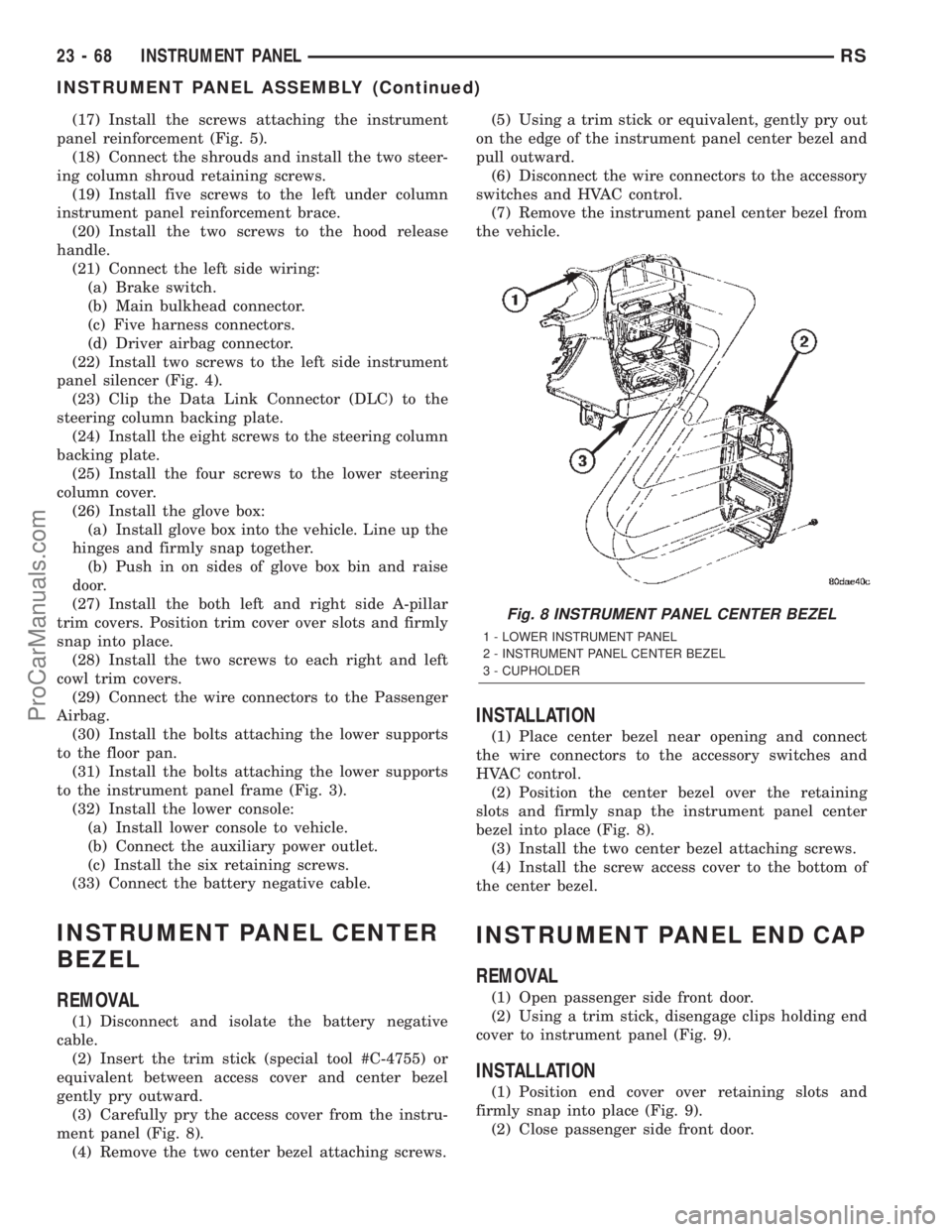
(3) Carefully pry the access cover from the instru-
ment panel (Fig. 8).
(4) Remove the two center bezel attaching screws.(5) Using a trim stick or equivalent, gently pry out
on the edge of the instrument panel center bezel and
pull outward.
(6) Disconnect the wire connectors to the accessory
switches and HVAC control.
(7) Remove the instrument panel center bezel from
the vehicle.
INSTALLATION
(1) Place center bezel near opening and connect
the wire connectors to the accessory switches and
HVAC control.
(2) Position the center bezel over the retaining
slots and firmly snap the instrument panel center
bezel into place (Fig. 8).
(3) Install the two center bezel attaching screws.
(4) Install the screw access cover to the bottom of
the center bezel.
INSTRUMENT PANEL END CAP
REMOVAL
(1) Open passenger side front door.
(2) Using a trim stick, disengage clips holding end
cover to instrument panel (Fig. 9).
INSTALLATION
(1) Position end cover over retaining slots and
firmly snap into place (Fig. 9).
(2) Close passenger side front door.
Fig. 8 INSTRUMENT PANEL CENTER BEZEL
1 - LOWER INSTRUMENT PANEL
2 - INSTRUMENT PANEL CENTER BEZEL
3 - CUPHOLDER
23 - 68 INSTRUMENT PANELRS
INSTRUMENT PANEL ASSEMBLY (Continued)
ProCarManuals.com