2002 CHRYSLER TOWN AND COUNTRY Hoses
[x] Cancel search: HosesPage 1727 of 2399
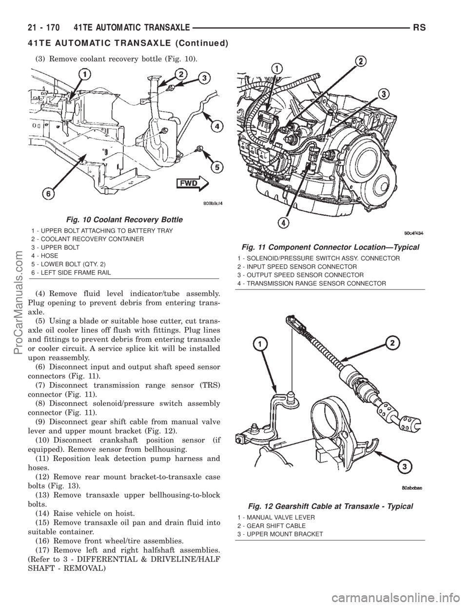
(3) Remove coolant recovery bottle (Fig. 10).
(4) Remove fluid level indicator/tube assembly.
Plug opening to prevent debris from entering trans-
axle.
(5) Using a blade or suitable hose cutter, cut trans-
axle oil cooler lines off flush with fittings. Plug lines
and fittings to prevent debris from entering transaxle
or cooler circuit. A service splice kit will be installed
upon reassembly.
(6) Disconnect input and output shaft speed sensor
connectors (Fig. 11).
(7) Disconnect transmission range sensor (TRS)
connector (Fig. 11).
(8) Disconnect solenoid/pressure switch assembly
connector (Fig. 11).
(9) Disconnect gear shift cable from manual valve
lever and upper mount bracket (Fig. 12).
(10) Disconnect crankshaft position sensor (if
equipped). Remove sensor from bellhousing.
(11) Reposition leak detection pump harness and
hoses.
(12) Remove rear mount bracket-to-transaxle case
bolts (Fig. 13).
(13) Remove transaxle upper bellhousing-to-block
bolts.
(14) Raise vehicle on hoist.
(15) Remove transaxle oil pan and drain fluid into
suitable container.
(16) Remove front wheel/tire assemblies.
(17) Remove left and right halfshaft assemblies.
(Refer to 3 - DIFFERENTIAL & DRIVELINE/HALF
SHAFT - REMOVAL)
Fig. 10 Coolant Recovery Bottle
1 - UPPER BOLT ATTACHING TO BATTERY TRAY
2 - COOLANT RECOVERY CONTAINER
3 - UPPER BOLT
4 - HOSE
5 - LOWER BOLT (QTY. 2)
6 - LEFT SIDE FRAME RAIL
Fig. 11 Component Connector LocationÐTypical
1 - SOLENOID/PRESSURE SWITCH ASSY. CONNECTOR
2 - INPUT SPEED SENSOR CONNECTOR
3 - OUTPUT SPEED SENSOR CONNECTOR
4 - TRANSMISSION RANGE SENSOR CONNECTOR
Fig. 12 Gearshift Cable at Transaxle - Typical
1 - MANUAL VALVE LEVER
2 - GEAR SHIFT CABLE
3 - UPPER MOUNT BRACKET
21 - 170 41TE AUTOMATIC TRANSAXLERS
41TE AUTOMATIC TRANSAXLE (Continued)
ProCarManuals.com
Page 2033 of 2399
COWL GRILLE
REMOVAL
(1) Remove wiper arms. (Refer to 8 - ELECTRI-
CAL/WIPERS/WASHERS/WIPER ARMS -
REMOVAL)
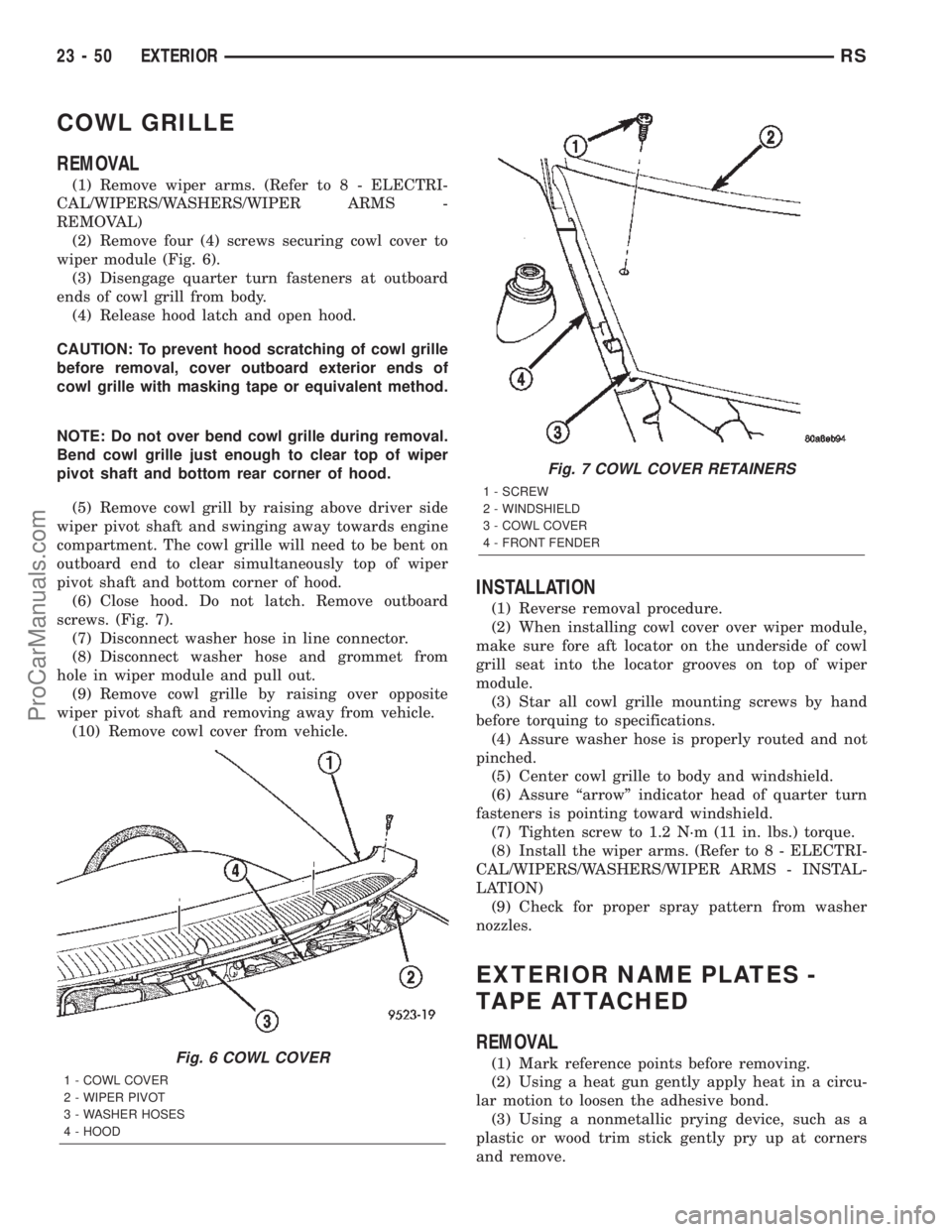
(2) Remove four (4) screws securing cowl cover to
wiper module (Fig. 6).
(3) Disengage quarter turn fasteners at outboard
ends of cowl grill from body.
(4) Release hood latch and open hood.
CAUTION: To prevent hood scratching of cowl grille
before removal, cover outboard exterior ends of
cowl grille with masking tape or equivalent method.
NOTE: Do not over bend cowl grille during removal.
Bend cowl grille just enough to clear top of wiper
pivot shaft and bottom rear corner of hood.
(5) Remove cowl grill by raising above driver side
wiper pivot shaft and swinging away towards engine
compartment. The cowl grille will need to be bent on
outboard end to clear simultaneously top of wiper
pivot shaft and bottom corner of hood.
(6) Close hood. Do not latch. Remove outboard
screws. (Fig. 7).
(7) Disconnect washer hose in line connector.
(8) Disconnect washer hose and grommet from
hole in wiper module and pull out.
(9) Remove cowl grille by raising over opposite
wiper pivot shaft and removing away from vehicle.
(10) Remove cowl cover from vehicle.
INSTALLATION
(1) Reverse removal procedure.
(2) When installing cowl cover over wiper module,
make sure fore aft locator on the underside of cowl
grill seat into the locator grooves on top of wiper
module.
(3) Star all cowl grille mounting screws by hand
before torquing to specifications.
(4) Assure washer hose is properly routed and not
pinched.
(5) Center cowl grille to body and windshield.
(6) Assure ªarrowº indicator head of quarter turn
fasteners is pointing toward windshield.
(7) Tighten screw to 1.2 N´m (11 in. lbs.) torque.
(8) Install the wiper arms. (Refer to 8 - ELECTRI-
CAL/WIPERS/WASHERS/WIPER ARMS - INSTAL-
LATION)
(9) Check for proper spray pattern from washer
nozzles.
EXTERIOR NAME PLATES -
TAPE ATTACHED
REMOVAL
(1) Mark reference points before removing.
(2) Using a heat gun gently apply heat in a circu-
lar motion to loosen the adhesive bond.
(3) Using a nonmetallic prying device, such as a
plastic or wood trim stick gently pry up at corners
and remove.Fig. 6 COWL COVER
1 - COWL COVER
2 - WIPER PIVOT
3 - WASHER HOSES
4 - HOOD
Fig. 7 COWL COVER RETAINERS
1 - SCREW
2 - WINDSHIELD
3 - COWL COVER
4 - FRONT FENDER
23 - 50 EXTERIORRS
ProCarManuals.com
Page 2249 of 2399
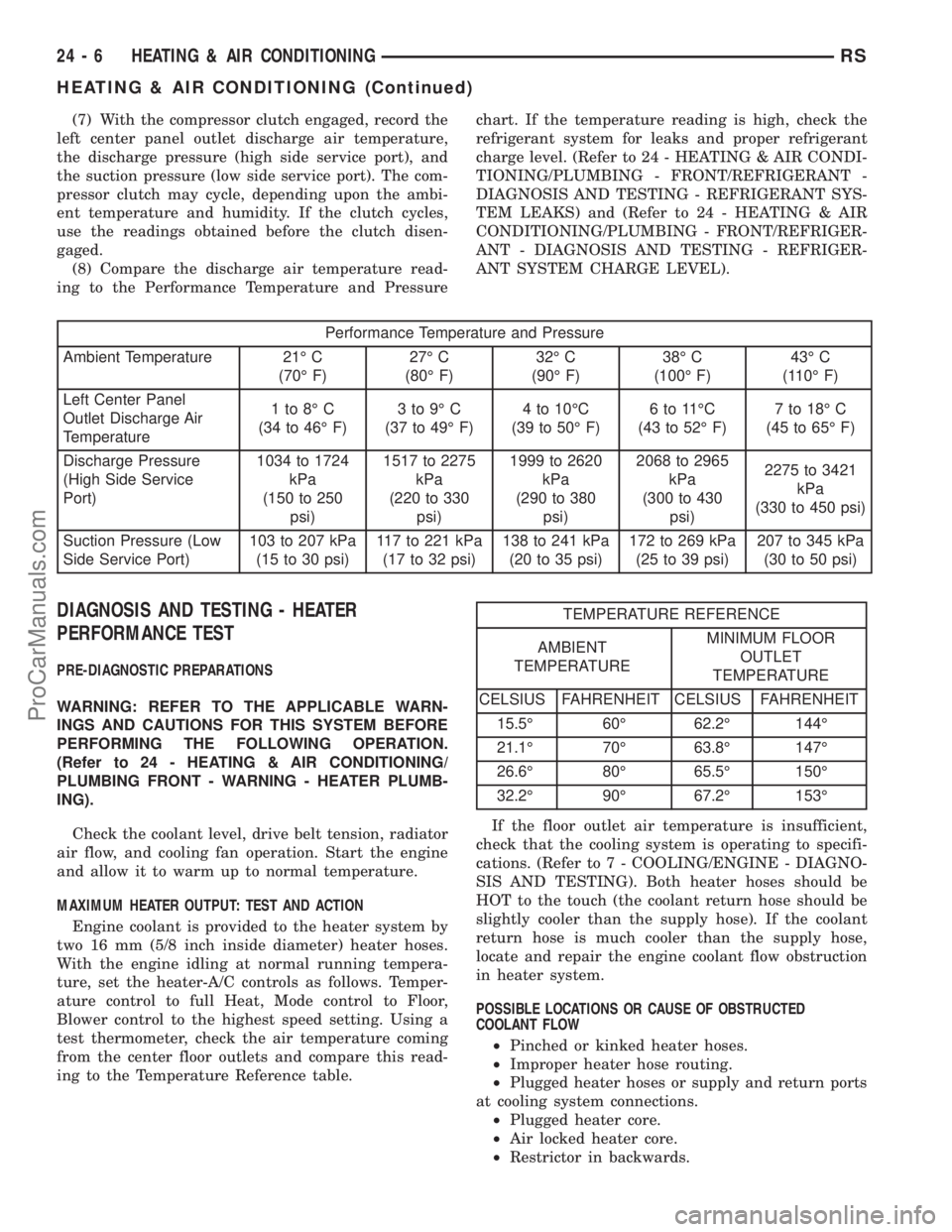
(7) With the compressor clutch engaged, record the
left center panel outlet discharge air temperature,
the discharge pressure (high side service port), and
the suction pressure (low side service port). The com-
pressor clutch may cycle, depending upon the ambi-
ent temperature and humidity. If the clutch cycles,
use the readings obtained before the clutch disen-
gaged.
(8) Compare the discharge air temperature read-
ing to the Performance Temperature and Pressurechart. If the temperature reading is high, check the
refrigerant system for leaks and proper refrigerant
charge level. (Refer to 24 - HEATING & AIR CONDI-
TIONING/PLUMBING - FRONT/REFRIGERANT -
DIAGNOSIS AND TESTING - REFRIGERANT SYS-
TEM LEAKS) and (Refer to 24 - HEATING & AIR
CONDITIONING/PLUMBING - FRONT/REFRIGER-
ANT - DIAGNOSIS AND TESTING - REFRIGER-
ANT SYSTEM CHARGE LEVEL).
Performance Temperature and Pressure
Ambient Temperature 21É C
(70É F)27É C
(80É F)32É C
(90É F)38É C
(100É F)43É C
(110É F)
Left Center Panel
Outlet Discharge Air
Temperature1to8ÉC
(34 to 46É F)3to9ÉC
(37 to 49É F)4 to 10ÉC
(39 to 50É F)6to11ÉC
(43 to 52É F)7 to 18É C
(45 to 65É F)
Discharge Pressure
(High Side Service
Port)1034 to 1724
kPa
(150 to 250
psi)1517 to 2275
kPa
(220 to 330
psi)1999 to 2620
kPa
(290 to 380
psi)2068 to 2965
kPa
(300 to 430
psi)2275 to 3421
kPa
(330 to 450 psi)
Suction Pressure (Low
Side Service Port)103 to 207 kPa
(15 to 30 psi)117 to 221 kPa
(17 to 32 psi)138 to 241 kPa
(20 to 35 psi)172 to 269 kPa
(25 to 39 psi)207 to 345 kPa
(30 to 50 psi)
DIAGNOSIS AND TESTING - HEATER
PERFORMANCE TEST
PRE-DIAGNOSTIC PREPARATIONS
WARNING: REFER TO THE APPLICABLE WARN-
INGS AND CAUTIONS FOR THIS SYSTEM BEFORE
PERFORMING THE FOLLOWING OPERATION.
(Refer to 24 - HEATING & AIR CONDITIONING/
PLUMBING FRONT - WARNING - HEATER PLUMB-
ING).
Check the coolant level, drive belt tension, radiator
air flow, and cooling fan operation. Start the engine
and allow it to warm up to normal temperature.
MAXIMUM HEATER OUTPUT: TEST AND ACTION
Engine coolant is provided to the heater system by
two 16 mm (5/8 inch inside diameter) heater hoses.
With the engine idling at normal running tempera-
ture, set the heater-A/C controls as follows. Temper-
ature control to full Heat, Mode control to Floor,
Blower control to the highest speed setting. Using a
test thermometer, check the air temperature coming
from the center floor outlets and compare this read-
ing to the Temperature Reference table.
TEMPERATURE REFERENCE
AMBIENT
TEMPERATUREMINIMUM FLOOR
OUTLET
TEMPERATURE
CELSIUS FAHRENHEIT CELSIUS FAHRENHEIT
15.5É 60É 62.2É 144É
21.1É 70É 63.8É 147É
26.6É 80É 65.5É 150É
32.2É 90É 67.2É 153É
If the floor outlet air temperature is insufficient,
check that the cooling system is operating to specifi-
cations. (Refer to 7 - COOLING/ENGINE - DIAGNO-
SIS AND TESTING). Both heater hoses should be
HOT to the touch (the coolant return hose should be
slightly cooler than the supply hose). If the coolant
return hose is much cooler than the supply hose,
locate and repair the engine coolant flow obstruction
in heater system.
POSSIBLE LOCATIONS OR CAUSE OF OBSTRUCTED
COOLANT FLOW
²Pinched or kinked heater hoses.
²Improper heater hose routing.
²Plugged heater hoses or supply and return ports
at cooling system connections.
²Plugged heater core.
²Air locked heater core.
²Restrictor in backwards.
24 - 6 HEATING & AIR CONDITIONINGRS
HEATING & AIR CONDITIONING (Continued)
ProCarManuals.com
Page 2292 of 2399
HVAC HOUSING
REMOVAL
WARNING: REFER TO THE APPLICABLE WARN-
INGS AND CAUTIONS FOR THIS SYSTEM BEFORE
PERFORMING THE FOLLOWING OPERATION.
(Refer to 24 - HEATING & AIR CONDITIONING/
PLUMBING - FRONT - WARNING - A/C PLUMBING),
(Refer to 24 - HEATING & AIR CONDITIONING/
PLUMBING - FRONT - CAUTION - A/C PLUMBING),
and (Refer to 24 - HEATING & AIR CONDITIONING/
PLUMBING - FRONT - WARNING - HEATER PLUMB-
ING).
WARNING: ON VEHICLES EQUIPPED WITH AIR-
BAGS, DISABLE THE AIRBAG SYSTEM BEFORE
ATTEMPTING ANY STEERING WHEEL, STEERING
COLUMN, OR INSTRUMENT PANEL COMPONENT
DIAGNOSIS OR SERVICE. DISCONNECT AND ISO-
LATE THE BATTERY NEGATIVE (GROUND) CABLE,
THEN WAIT TWO MINUTES FOR THE AIRBAG SYS-
TEM CAPACITOR TO DISCHARGE BEFORE PER-
FORMING FURTHER DIAGNOSIS OR SERVICE. THIS
IS THE ONLY SURE WAY TO DISABLE THE AIRBAG
SYSTEM. FAILURE TO TAKE THE PROPER PRE-
CAUTIONS COULD RESULT IN ACCIDENTAL AIR-
BAG DEPLOYMENT AND POSSIBLE PERSONAL
INJURY.
(1) Recover the refrigerant from the refrigerant
system. (Refer to 24 - HEATING & AIR CONDI-
TIONING/PLUMBING - FRONT/REFRIGERANT -
STANDARD PROCEDURE - REFRIGERANT
RECOVERY).
(2) Drain the engine cooling system. (Refer to 7 -
COOLING - STANDARD PROCEDURE - COOLING
SYSTEM DRAIN).
(3) Disconnect and isolate the battery negative
cable.
(4) Disconnect the liquid line and suction line from
the expansion valve. (Refer to 24 - HEATING & AIR
CONDITIONING/PLUMBING - FRONT/LIQUID
LINE - REMOVAL) and (Refer to 24 - HEATING &
AIR CONDITIONING/PLUMBING - FRONT/SUC-
TION LINE - REMOVAL).
(5) Disconnect the heater hoses from the heater
core tubes. (Refer to 24 - HEATING & AIR CONDI-
TIONING/PLUMBING - FRONT/HEATER HOSE -
REMOVAL).
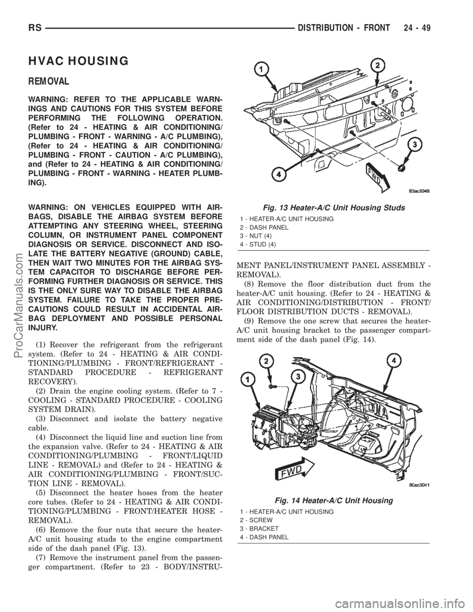
(6) Remove the four nuts that secure the heater-
A/C unit housing studs to the engine compartment
side of the dash panel (Fig. 13).
(7) Remove the instrument panel from the passen-
ger compartment. (Refer to 23 - BODY/INSTRU-MENT PANEL/INSTRUMENT PANEL ASSEMBLY -
REMOVAL).
(8) Remove the floor distribution duct from the
heater-A/C unit housing. (Refer to 24 - HEATING &
AIR CONDITIONING/DISTRIBUTION - FRONT/
FLOOR DISTRIBUTION DUCTS - REMOVAL).
(9) Remove the one screw that secures the heater-
A/C unit housing bracket to the passenger compart-
ment side of the dash panel (Fig. 14).
Fig. 13 Heater-A/C Unit Housing Studs
1 - HEATER-A/C UNIT HOUSING
2 - DASH PANEL
3 - NUT (4)
4 - STUD (4)
Fig. 14 Heater-A/C Unit Housing
1 - HEATER-A/C UNIT HOUSING
2 - SCREW
3 - BRACKET
4 - DASH PANEL
RSDISTRIBUTION - FRONT24-49
ProCarManuals.com
Page 2293 of 2399
(10) Pull the heater-A/C unit housing rearward far
enough for the mounting studs to clear the dash
panel and remove the unit from the passenger com-
partment.
INSTALLATION
(1) Position the heater-A/C unit housing against
the dash panel in the passenger compartment with
the four mounting studs located in their proper
mounting holes in the dash panel.
(2) Install and tighten the one screw that secures
the heater-A/C unit housing bracket to the passenger
compartment side of the dash panel. Tighten the
screw to 3 N´m (26 in. lbs.).
(3) Install and tighten the four nuts that secure
the heater-A/C unit housing studs to the engine com-
partment side of the dash panel. Tighten the nuts to
7 N´m (62 in. lbs.).
(4) Reinstall the floor distribution duct onto the
heater-A/C unit housing. (Refer to 24 - HEATING &
AIR CONDITIONING/DISTRIBUTION - FRONT/
FLOOR DISTRIBUTION DUCTS - INSTALLATION).
(5) Reinstall the instrument panel into the passen-
ger compartment. (Refer to 23 - BODY/INSTRU-
MENT PANEL/INSTRUMENT PANEL ASSEMBLY -
INSTALLATION).
(6) Reconnect the heater hoses to the heater core
tubes. (Refer to 24 - HEATING & AIR CONDITION-
ING/PLUMBING - FRONT/HEATER HOSE -
INSTALLATION).
(7) Reconnect the suction line and liquid line to
the expansion valve. (Refer to 24 - HEATING & AIR
CONDITIONING/PLUMBING - FRONT/SUCTION
LINE - INSTALLATION) and (Refer to 24 - HEAT-
ING & AIR CONDITIONING/PLUMBING - FRONT/
LIQUID LINE - INSTALLATION).
(8) Reconnect the battery negative cable.
(9) Refill the engine cooling system. (Refer to 7 -
COOLING - STANDARD PROCEDURE - COOLING
SYSTEM REFILL).
(10) Evacuate the refrigerant system. (Refer to 24
- HEATING & AIR CONDITIONING/PLUMBING -
FRONT/REFRIGERANT - STANDARD PROCE-
DURE - REFRIGERANT SYSTEM EVACUATE).
(11) Charge the refrigerant system. (Refer to 24 -
HEATING & AIR CONDITIONING/PLUMBING -
FRONT/REFRIGERANT - STANDARD PROCE-
DURE - REFRIGERANT SYSTEM CHARGE).
PANEL DUCTS
REMOVAL
WARNING: ON VEHICLES EQUIPPED WITH AIR-
BAGS, DISABLE THE AIRBAG SYSTEM BEFORE
ATTEMPTING ANY STEERING WHEEL, STEERING
COLUMN, OR INSTRUMENT PANEL COMPONENT
DIAGNOSIS OR SERVICE. DISCONNECT AND ISO-
LATE THE BATTERY NEGATIVE (GROUND) CABLE,
THEN WAIT TWO MINUTES FOR THE AIRBAG SYS-
TEM CAPACITOR TO DISCHARGE BEFORE PER-
FORMING FURTHER DIAGNOSIS OR SERVICE. THIS
IS THE ONLY SURE WAY TO DISABLE THE AIRBAG
SYSTEM. FAILURE TO TAKE THE PROPER PRE-
CAUTIONS COULD RESULT IN ACCIDENTAL AIR-
BAG DEPLOYMENT AND POSSIBLE PERSONAL
INJURY.
(1) Disconnect and isolate the battery negative
cable.
(2) Remove the instrument panel from the vehicle.
(Refer to 23 - BODY/INSTRUMENT PANEL/IN-
STRUMENT PANEL ASSEMBLY - REMOVAL).
(3) Place the instrument panel face down on a
suitable work surface. Be certain to take the proper
precautions to protect the face of the instrument
panel from cosmetic damage.
(4) Remove the fasteners that secure the panel
ducts to the instrument panel armature.
(5) Disengage the panel ducts from the panel out-
lets.
(6) Remove the panel ducts from the instrument
panel.
INSTALLATION
(1) Position the panel ducts to the instrument
panel.
(2) Engage the panel ducts to the panel outlets.
(3) Install the fasteners that secure the panel
ducts to the instrument panel armature.
(4) Reinstall the instrument panel into the vehicle.
(Refer to 23 - BODY/INSTRUMENT PANEL/IN-
STRUMENT PANEL ASSEMBLY - INSTALLA-
TION).
(5) Reconnect the battery negative cable.
24 - 50 DISTRIBUTION - FRONTRS
HVAC HOUSING (Continued)
ProCarManuals.com
Page 2299 of 2399
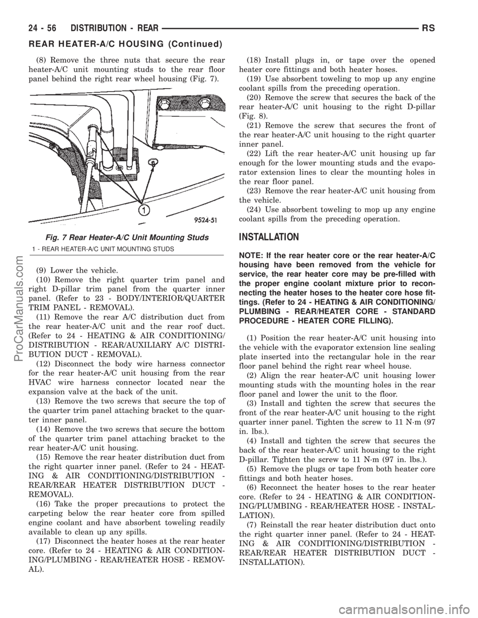
(8) Remove the three nuts that secure the rear
heater-A/C unit mounting studs to the rear floor
panel behind the right rear wheel housing (Fig. 7).
(9) Lower the vehicle.
(10) Remove the right quarter trim panel and
right D-pillar trim panel from the quarter inner
panel. (Refer to 23 - BODY/INTERIOR/QUARTER
TRIM PANEL - REMOVAL).
(11) Remove the rear A/C distribution duct from
the rear heater-A/C unit and the rear roof duct.
(Refer to 24 - HEATING & AIR CONDITIONING/
DISTRIBUTION - REAR/AUXILIARY A/C DISTRI-
BUTION DUCT - REMOVAL).
(12) Disconnect the body wire harness connector
for the rear heater-A/C unit housing from the rear
HVAC wire harness connector located near the
expansion valve at the back of the unit.
(13) Remove the two screws that secure the top of
the quarter trim panel attaching bracket to the quar-
ter inner panel.
(14) Remove the two screws that secure the bottom
of the quarter trim panel attaching bracket to the
rear heater-A/C unit housing.
(15) Remove the rear heater distribution duct from
the right quarter inner panel. (Refer to 24 - HEAT-
ING & AIR CONDITIONING/DISTRIBUTION -
REAR/REAR HEATER DISTRIBUTION DUCT -
REMOVAL).
(16) Take the proper precautions to protect the
carpeting below the rear heater core from spilled
engine coolant and have absorbent toweling readily
available to clean up any spills.
(17) Disconnect the heater hoses at the rear heater
core. (Refer to 24 - HEATING & AIR CONDITION-
ING/PLUMBING - REAR/HEATER HOSE - REMOV-
AL).(18) Install plugs in, or tape over the opened
heater core fittings and both heater hoses.
(19) Use absorbent toweling to mop up any engine
coolant spills from the preceding operation.
(20) Remove the screw that secures the back of the
rear heater-A/C unit housing to the right D-pillar
(Fig. 8).
(21) Remove the screw that secures the front of
the rear heater-A/C unit housing to the right quarter
inner panel.
(22) Lift the rear heater-A/C unit housing up far
enough for the lower mounting studs and the evapo-
rator extension lines to clear the mounting holes in
the rear floor panel.
(23) Remove the rear heater-A/C unit housing from
the vehicle.
(24) Use absorbent toweling to mop up any engine
coolant spills from the preceding operation.
INSTALLATION
NOTE: If the rear heater core or the rear heater-A/C
housing have been removed from the vehicle for
service, the rear heater core may be pre-filled with
the proper engine coolant mixture prior to recon-
necting the heater hoses to the heater core hose fit-
tings. (Refer to 24 - HEATING & AIR CONDITIONING/
PLUMBING - REAR/HEATER CORE - STANDARD
PROCEDURE - HEATER CORE FILLING).
(1) Position the rear heater-A/C unit housing into
the vehicle with the evaporator extension line sealing
plate inserted into the rectangular hole in the rear
floor panel behind the right rear wheel house.
(2) Align the rear heater-A/C unit housing lower
mounting studs with the mounting holes in the rear
floor panel and lower the unit to the floor.
(3) Install and tighten the screw that secures the
front of the rear heater-A/C unit housing to the right
quarter inner panel. Tighten the screw to 11 N´m (97
in. lbs.).
(4) Install and tighten the screw that secures the
back of the rear heater-A/C unit housing to the right
D-pillar. Tighten the screw to 11 N´m (97 in. lbs.).
(5) Remove the plugs or tape from both heater core
fittings and both heater hoses.
(6) Reconnect the heater hoses to the rear heater
core. (Refer to 24 - HEATING & AIR CONDITION-
ING/PLUMBING - REAR/HEATER HOSE - INSTAL-
LATION).
(7) Reinstall the rear heater distribution duct onto
the right quarter inner panel. (Refer to 24 - HEAT-
ING & AIR CONDITIONING/DISTRIBUTION -
REAR/REAR HEATER DISTRIBUTION DUCT -
INSTALLATION).
Fig. 7 Rear Heater-A/C Unit Mounting Studs
1 - REAR HEATER-A/C UNIT MOUNTING STUDS
24 - 56 DISTRIBUTION - REARRS
REAR HEATER-A/C HOUSING (Continued)
ProCarManuals.com
Page 2302 of 2399
PLUMBING - FRONT
TABLE OF CONTENTS
page page
PLUMBING - FRONT
WARNING
WARNING...........................60
WARNING...........................60
WARNING - A/C PLUMBING.............60
CAUTION - A/C PLUMBING...............61
COMPRESSOR
DESCRIPTION.........................62
OPERATION...........................62
DIAGNOSIS AND TESTING - COMPRESSOR
NOISE DIAGNOSIS....................62
REMOVAL
REMOVAL - COMPRESSOR.............63
REMOVAL - COMPRESSOR MOUNTING
BRACKET - 2.4L ENGINE...............64
INSTALLATION
INSTALLATION - COMPRESSOR..........64
INSTALLATION - COMPRESSOR
MOUNTING BRACKET - 2.4L ENGINE......65
CONDENSER
DESCRIPTION.........................65
OPERATION...........................65
REMOVAL.............................65
INSTALLATION.........................66
DISCHARGE LINE
REMOVAL.............................67
INSTALLATION.........................68
EVAPORATOR
DESCRIPTION.........................68
OPERATION...........................68
REMOVAL.............................69
INSTALLATION.........................70
EXPANSION VALVE
DESCRIPTION.........................71
OPERATION...........................71
DIAGNOSIS AND TESTING - EXPANSION
VALVE ..............................71
REMOVAL.............................72
INSTALLATION.........................73
HEATER CORE
DESCRIPTION.........................73
OPERATION...........................73
REMOVAL
REMOVAL- HEATER CORE EXTENSION
TUBES.............................74
REMOVAL - HEATER CORE.............75
INSTALLATION
INSTALLATION- HEATER CORE
EXTENSION TUBES...................76
INSTALLATION - HEATER CORE..........77HEATER HOSE
REMOVAL.............................78
INSTALLATION.........................79
HEATER HOSES - DIESEL SUPPLEMENTAL
HEATER - BUX
REMOVAL.............................80
INSTALLATION.........................80
HEATER PIPES - DIESEL SUPPLEMENTAL
HEATER - BUX
REMOVAL.............................80
INSTALLATION.........................82
LIQUID LINE
REMOVAL.............................82
INSTALLATION.........................84
RECEIVER/DRIER
DESCRIPTION.........................85
OPERATION...........................85
REMOVAL.............................85
INSTALLATION.........................86
REFRIGERANT
DESCRIPTION.........................87
OPERATION...........................87
DIAGNOSIS AND TESTING
DIAGNOSIS AND TESTING - REFRIGERANT
SYSTEM CHARGE LEVEL...............87
DIAGNOSIS AND TESTING - REFRIGERANT
SYSTEM LEAKS......................88
DIAGNOSIS AND TESTING - REFRIGERANT
SYSTEM CHARGE LEVEL 2.5L DIESEL.....89
STANDARD PROCEDURE
STANDARD PROCEDURE - REFRIGERANT
SYSTEM SERVICE EQUIPMENT..........90
STANDARD PROCEDURE - REFRIGERANT
SYSTEM CHARGE.....................91
STANDARD PROCEDURE - REFRIGERANT
SYSTEM EVACUATE...................92
STANDARD PROCEDURE - REFRIGERANT
RECOVERY..........................93
REFRIGERANT OIL
DESCRIPTION.........................93
OPERATION...........................93
STANDARD PROCEDURE - REFRIGERANT
OIL LEVEL...........................93
SUCTION LINE
REMOVAL.............................94
INSTALLATION.........................95
SERVICE PORTS
REMOVAL.............................95
INSTALLATION.........................96
RSPLUMBING - FRONT24-59
ProCarManuals.com
Page 2303 of 2399
PLUMBING - FRONT
WARNING
WARNING
WARNING: DO NOT OPERATE DCHA IN AN
ENCLOSED AREA SUCH AS A GARAGE THAT
DOES NOT HAVE EXHAUST VENTILATION FACILI-
TIES. ALWAYS VENT THE DCHA'S EXHAUST WHEN
OPERATING THE DCHA. FAILURE TO FOLLOW
THESE INSTRUCTION MAY RESULT IN PERSONAL
INJURY OR DEATH.
ALLOW THE DCHA ASSEMBLY TO COOL BEFORE
PERFORMING A COMPONENT INSPECTION/RE-
PAIR/REPLACEMENT. FAILURE TO FOLLOW THESE
INSTRUCTIONS MY RESULT IN PERSONAL INJURY.
VERIFY THAT ALL DCHA FUEL LINES ARE
SECURELY FASTENED TO THEIR RESPECTIVE
COMPONENTS BEFORE THIS PROCEDURE.
WARNING
WARNING:: THE ENGINE COOLING SYSTEM IS
DESIGNED TO DEVELOP INTERNAL PRESSURES
OF 97 TO 123 KILOPASCALS (14 TO 18 POUNDS
PER SQUARE INCH). DO NOT REMOVE OR
LOOSEN THE COOLANT PRESSURE CAP, CYLIN-
DER BLOCK DRAIN PLUGS, RADIATOR DRAIN,
RADIATOR HOSES, HEATER HOSES, OR HOSE
CLAMPS WHILE THE SYSTEM IS HOT AND UNDER
PRESSURE. FAILURE TO OBSERVE THIS WARNING
CAN RESULT IN SERIOUS BURNS FROM THE
HEATED ENGINE COOLANT. ALLOW THE VEHICLE
TO COOL FOR A MINIMUM OF 15 MINUTES
BEFORE OPENING THE COOLING SYSTEM FOR
SERVICE.
WARNING: THE ENGINE COOLING SYSTEM CON-
TAINS ANTIFREEZE. ANTIFREEZE IS AN ETHYLENE
GLYCOL BASED COOLANT AND IS HARMFUL IF
SWALLOWED OR IF THE VAPORS ARE INHALED. IF
SWALLOWED, DRINK TWO GLASSES OF WATER
AND INDUCE VOMITING. IF VAPORS ARE INHALED,
MOVE TO AN AREA FOR FRESH AIR. SEEK MEDI-
CAL ATTENTION IMMEDIATELY. DO NOT STORE IN
OPEN OR UNMARKED CONTAINERS. WASH SKIN
AND CLOTHING THOROUGHLY AFTER COMING IN
CONTACT WITH ETHYLENE GLYCOL. KEEP OUT
OF REACH OF CHILDREN.
WARNING: DISPOSE OF ETHYLENE GLYCOL
BASED COOLANT PROPERLY. CONTACT YOURDEALER OR A LOCAL GOVERNMENT AGENCY FOR
THE LOCATION OF AN APPROVED ETHYLENE GLY-
COL COLLECTION AND/OR RECYCLING CENTER IN
YOUR AREA.
WARNING - A/C PLUMBING
WARNING:: THE AIR CONDITIONING SYSTEM CON-
TAINS REFRIGERANT UNDER HIGH PRESSURE.
SEVERE PERSONAL INJURY MAY RESULT FROM
IMPROPER SERVICE PROCEDURES. REPAIRS
SHOULD ONLY BE PERFORMED BY QUALIFIED
SERVICE PERSONNEL.
WARNING: AVOID BREATHING THE REFRIGERANT
AND REFRIGERANT OIL VAPOR OR MIST. EXPO-
SURE MAY IRRITATE THE EYES, NOSE, AND/OR
THROAT. WEAR EYE PROTECTION WHEN SERVIC-
ING THE AIR CONDITIONING REFRIGERANT SYS-
TEM. SERIOUS EYE INJURY CAN RESULT FROM
DIRECT CONTACT WITH THE REFRIGERANT. IF
EYE CONTACT OCCURS, SEEK MEDICAL ATTEN-
TION IMMEDIATELY.
WARNING: DO NOT EXPOSE THE REFRIGERANT
TO OPEN FLAME. POISONOUS GAS IS CREATED
WHEN REFRIGERANT IS BURNED. AN ELEC-
TRONIC LEAK DETECTOR IS RECOMMENDED.
WARNING: IF ACCIDENTAL SYSTEM DISCHARGE
OCCURS, VENTILATE THE WORK AREA BEFORE
RESUMING SERVICE. LARGE AMOUNTS OF
REFRIGERANT RELEASED IN A CLOSED WORK
AREA WILL DISPLACE THE OXYGEN AND CAUSE
SUFFOCATION.
WARNING: THE EVAPORATION RATE OF R-134a
REFRIGERANT AT AVERAGE TEMPERATURE AND
ALTITUDE IS EXTREMELY HIGH. AS A RESULT,
ANYTHING THAT COMES IN CONTACT WITH THE
REFRIGERANT WILL FREEZE. ALWAYS PROTECT
THE SKIN OR DELICATE OBJECTS FROM DIRECT
CONTACT WITH THE REFRIGERANT.
WARNING: THE R-134a SERVICE EQUIPMENT OR
THE VEHICLE REFRIGERANT SYSTEM SHOULD
NOT BE PRESSURE TESTED OR LEAK TESTED
WITH COMPRESSED AIR. SOME MIXTURES OF AIR
AND R-134a HAVE BEEN SHOWN TO BE COMBUS-
TIBLE AT ELEVATED PRESSURES. THESE MIX-
TURES ARE POTENTIALLY DANGEROUS, AND MAY
RESULT IN FIRE OR EXPLOSION CAUSING INJURY
OR PROPERTY DAMAGE.
24 - 60 PLUMBING - FRONTRS
ProCarManuals.com