2002 CHRYSLER TOWN AND COUNTRY High pressure lines
[x] Cancel search: High pressure linesPage 156 of 2399
allow the brake fluid to drain out of the master cyl-
inder reservoir when the lines are opened.
(2) Raise the vehicle. Refer to HOISTING in
LUBRICATION AND MAINTENANCE.
(3) Remove the front tire and wheel assembly.
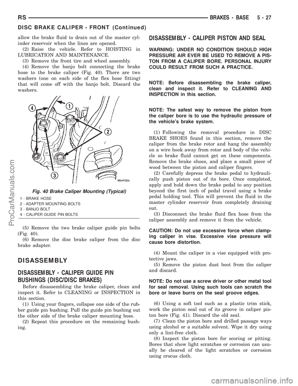
(4) Remove the banjo bolt connecting the brake
hose to the brake caliper (Fig. 40). There are two
washers (one on each side of the flex hose fitting)
that will come off with the banjo bolt. Discard the
washers.
(5) Remove the two brake caliper guide pin bolts
(Fig. 40).
(6) Remove the disc brake caliper from the disc
brake adapter.
DISASSEMBLY
DISASSEMBLY - CALIPER GUIDE PIN
BUSHINGS (DISC/DISC BRAKES)
Before disassembling the brake caliper, clean and
inspect it. Refer to CLEANING or INSPECTION in
this section.
(1) Using your fingers, collapse one side of the rub-
ber guide pin bushing. Pull the guide pin bushing out
the other side of the brake caliper mounting boss.
(2) Repeat this procedure on the remaining bush-
ing.
DISASSEMBLY - CALIPER PISTON AND SEAL
WARNING: UNDER NO CONDITION SHOULD HIGH
PRESSURE AIR EVER BE USED TO REMOVE A PIS-
TON FROM A CALIPER BORE. PERSONAL INJURY
COULD RESULT FROM SUCH A PRACTICE.
NOTE: Before disassembling the brake caliper,
clean and inspect it. Refer to CLEANING AND
INSPECTION in this section.
NOTE: The safest way to remove the piston from
the caliper bore is to use the hydraulic pressure of
the vehicle's brake system.
(1) Following the removal procedure in DISC
BRAKE SHOES found in this section, remove the
caliper from the brake rotor and hang the assembly
on a wire hook away from rotor and body of the vehi-
cle so brake fluid cannot get on these components.
Remove the brake shoes, and place a small piece of
wood between the piston and caliper fingers.
(2) Carefully depress the brake pedal to hydrauli-
cally push piston out of its bore. Once completed,
apply and hold down the brake pedal to any position
beyond the first inch of pedal travel using a brake
pedal holding tool. This will prevent the fluid in the
master cylinder reservoir from completely draining
out.
(3) Disconnect the brake fluid flex hose from the
caliper assembly and remove it from the vehicle.
CAUTION: Do not use excessive force when clamp-
ing caliper in vise. Excessive vise pressure will
cause bore distortion.
(4) Mount the caliper in a vise equipped with pro-
tective jaws.
(5) Remove the piston dust boot from the caliper
and discard.
NOTE: Do not use a screw driver or other metal tool
for seal removal. Using such tools can scratch the
bore or leave burrs on the seal groove edges.
(6) Using a soft tool such as a plastic trim stick,
work the piston seal out of its groove in caliper pis-
ton bore (Fig. 41). Discard the old seal.
(7) Clean the piston bore and drilled passage ways
using alcohol or a suitable solvent. Wipe it dry using
only a lint-free cloth.
(8) Inspect the piston bore for scoring or pitting.
Bores that show light scratches or corrosion can usu-
ally be cleared of the light scratches or corrosion
using crocus cloth.
Fig. 40 Brake Caliper Mounting (Typical)
1 - BRAKE HOSE
2 - ADAPTER MOUNTING BOLTS
3 - BANJO BOLT
4 - CALIPER GUIDE PIN BOLTS
RSBRAKES - BASE5-27
DISC BRAKE CALIPER - FRONT (Continued)
ProCarManuals.com
Page 186 of 2399
OPERATION - PROPORTIONING VALVE
(HEIGHT SENSING)
Vehicles not equipped with ABS use a height sens-
ing proportioning valve.
The height sensing proportioning valve operates
similarly to a standard proportioning valve in the fol-
lowing way. As hydraulic pressure is applied to the
valve, full input hydraulic pressure is supplied to the
rear brakes up to a certain pressure point, called the
split point. Beyond the split point, the proportioning
valve reduces the amount of hydraulic pressure to
the rear brakes according to a given ratio. Thus, on
light brake applications, approximately equal
hydraulic pressure will be transmitted to both the
front and rear brakes. Upon heavier brake applica-
tions, the hydraulic pressure transmitted to the rear
brakes will be lower than the front brakes. This will
prevent premature rear wheel lockup and skid.
Here is how the height sensing proportioning valve
differs from a standard proportioning valve. As the
height of the rear suspension changes, the height
sensing portion of the proportioning valve changes
the split point of the proportioning valve. When the
height of the rear suspension is low, the proportion-
ing valve interprets this as extra load and the split
point of the proportioning valve is raised to a higher
pressure to allow for more rear braking. When the
height of the rear suspension is high, the proportion-
ing valve interprets this as a light load and the split
point of the proportioning valve is lowered to a lower
pressure and rear braking is reduced.
The height sensing proportioning valve regulates
the pressure by sensing the load condition of the
vehicle through the movement of the proportioning
valve actuator lever (Fig. 91). As the position of the
rear axle changes, depending on the load the vehicle
is carrying, the movement is transferred to the pro-
portioning valve. The proportioning valve adjusts the
hydraulic pressure accordingly.
The height sensing proportioning valve allows the
brake system to maintain the optimal front to rear
brake balance regardless of the vehicle load condi-
tion. Under a light load condition, hydraulic pressure
to the rear brakes is minimized. As the rear load con-
dition increases, so does the hydraulic pressure to
the rear brakes.
DIAGNOSIS AND TESTING - PROPORTIONING
VALVE (HEIGHT SENSING)
CAUTION: The use of aftermarket load leveling or
load capacity increasing devices on this vehicle is
prohibited. Using air shock absorbers or helper
springs on this vehicle will cause the height sens-
ing proportioning valve to inappropriately reduce
the hydraulic pressure to the rear brakes. This inap-propriate reduction in hydraulic pressure potentially
could result in increased stopping distance of the
vehicle.
When a premature rear wheel skid is obtained on a
brake application, it may be an indication that the
hydraulic pressure to the rear brakes is above the
specified output from the proportioning valve. This
condition indicates a possible malfunction of the
height sensing proportioning valve, which will
require testing to verify that it is properly controlling
the hydraulic pressure allowed to the rear brakes.
Premature rear wheel skid may also be caused by
contaminated front or rear brake linings.
Prior to testing a proportioning valve for function,
check that all tire pressures are correct. Also, ensure
the front and rear brake linings are in satisfactory
condition.It is also necessary to verify that the
brakes shoe assemblies on a vehicle being
tested are either original equipment manufac-
turers (OEM) or original replacement brake
shoe assemblies meeting the OEM lining mate-
rial specification. This vehicles brake system is
not balanced for aftermarket brake shoe assem-
bly lining material.
If both front and rear brakes check OK, proceed
with the following test procedure for the height sens-
ing proportioning valve.
(1) Road test the vehicle to determine which rear
wheel brake is exhibiting premature wheel skid.
(2) Raise vehicle. (Refer to LUBRICATION &
MAINTENANCE/HOISTING - STANDARD PROCE-
DURE)
(3) Remove the chassis brake tube going to the
rear brake in question at the proportioning valve.
Remove the chassis brake tube coming from the junc-
tion block at the proportioning valve (Fig. 92).
(4) Install the appropriate fittings from Pressure
Test Fittings, Special Tool 6833, into the open ports
of the proportioning valve.
(5) Install the previously removed brake lines into
the Pressure Test Fittings. Tighten all tube nuts to
17 N´m (145 in. lbs.).
(6) Install a pressure gauge from Gauge Set, Spe-
cial Tool C-4007-A into the open port on each pres-
sure test fitting. Bleed air out of hose from pressure
test fittings to pressure gauges at the pressure
gauges. Then bleed air out of the brake line being
tested at that rear wheel brake bleeder.
NOTE: Actuator rod is a linear spring and is meant
to flex by design. When rod is raised, it will have
some curvature to it.
(7) Remove the screw fastening the proportioning
valve actuator rod bracket to the rear axle. Raise the
actuator lever to the full-upward position and hold it
there.
RSBRAKES - BASE5-57
PROPORTIONING VALVE (Continued)
ProCarManuals.com
Page 218 of 2399

The ABS portion of the brake system must be bled
separately. Use the following procedure to properly
bleed the brake hydraulic system including the ABS.
BLEEDING
When bleeding the ABS system, the following
bleeding sequence must be followed to insure com-
plete and adequate bleeding.
(1) Make sure all hydraulic fluid lines are installed
and properly torqued.
(2) Connect the DRBIIItscan tool to the diagnos-
tics connector. The diagnostic connector is located
under the lower steering column cover to the left of
the steering column.
(3) Using the DRB, check to make sure the CAB
does not have any fault codes stored. If it does, clear
them using the DRB.
WARNING: WHEN BLEEDING THE BRAKE SYSTEM
WEAR SAFETY GLASSES. A CLEAR BLEED TUBE
MUST BE ATTACHED TO THE BLEEDER SCREWS
AND SUBMERGED IN A CLEAR CONTAINER FILLED
PART WAY WITH CLEAN BRAKE FLUID. DIRECT
THE FLOW OF BRAKE FLUID AWAY FROM YOUR-
SELF AND THE PAINTED SURFACES OF THE VEHI-
CLE. BRAKE FLUID AT HIGH PRESSURE MAY
COME OUT OF THE BLEEDER SCREWS WHEN
OPENED.
(4) Bleed the base brake system using the stan-
dard pressure or manual bleeding procedure. (Refer
to 5 - BRAKES - BASE - STANDARD PROCEDURE)
(5) Using the DRB, select ANTILOCK BRAKES,
followed by MISCELLANEOUS, then BLEED
BRAKES. Follow the instructions displayed. When
the scan tool displays TEST COMPLETED, discon-
nect the scan tool and proceed.
(6) Bleed the base brake system a second time.
Check brake fluid level in the reservoir periodically
to prevent emptying, causing air to enter the hydrau-
lic system.
(7) Fill the master cylinder reservoir to the full
level.
(8) Test drive the vehicle to be sure the brakes are
operating correctly and that the brake pedal does not
feel spongy.
SPECIFICATIONS
ABS FASTENER TORQUE
(Refer to 5 - BRAKES - BASE - SPECIFICA-
TIONS)
TONE WHEEL RUNOUT
DESCRIPTION SPECIFICATION
Front Tone Wheel
Maximum Runout0.15 mm (0.006 in.)
Rear Tone Wheel
Maximum Runout0.15 mm (0.006 in.)
WHEEL SPEED SENSOR AIR GAP
DESCRIPTION SPECIFICATION
Front Sensor0.35 ± 1.20 mm
0.014 ± 0.047 in.
Rear Sensor0.40 ± 1.20 mm
0.016 ± 0.047 in.
FRONT WHEEL SPEED
SENSOR
REMOVAL
(1) Raise vehicle. (Refer to LUBRICATION &
MAINTENANCE/HOISTING - STANDARD PROCE-
DURE)
(2) Remove the tire and wheel assembly.
(3) Remove the sensor cable routing clamp screws.
CAUTION: When disconnecting the wheel speed
sensor from vehicle wiring harness, be careful not
to damage pins on connector
(4) Remove speed sensor cable grommets from
intermediate bracket on strut.
(5) Disconnect speed sensor cable from vehicle wir-
ing harness behind fender well shield.
(6) Remove the wheel speed sensor head mounting
bolt (Fig. 1).
(7) Remove sensor head from steering knuckle. If
sensor has seized due to corrosion,DO NOT USE
PLIERS ON SENSOR HEAD.Use a hammer and a
punch and tap edge of sensor ear, rocking the sensor
side-to-side until free.
(8) Remove front wheel speed sensor from vehicle.
INSTALLATION
CAUTION: Proper installation of wheel speed sen-
sor cables is critical to continued system operation.
Be sure that cables are installed in retainers. Fail-
ure to install cables in retainers as shown in this
section may result in contact with moving parts and
over extension of cables, resulting in an open cir-
cuit.
RSBRAKES - ABS5-89
BRAKES - ABS (Continued)
ProCarManuals.com
Page 240 of 2399
SERVICE DIAGNOSIS - IMPROPER CLUTCH RELEASE
CONDITION POSSIBLE CAUSES CORRECTION
CLUTCH DISC BINDS ON
INPUT SHAFT SPLINESClutch disc hub splines damaged
during installationClean, smooth, and lubricate disc and shaft
splines. Replace modular clutch assembly,
or clutch disc, and/or input shaft if splines
are severely damaged.
Input shaft splines rough, damaged. Clean input shaft splines. Then lube.
Corrosion or rust formations on
splines of input shaft and discClean input shaft splines and disc splines,
then lube
CLUTCH DISC RUSTED
TO FLYWHEEL AND/OR
PRESSURE PLATEOccurs in vehicles stored or not
driven for extended period of time.
Also occurs after steam cleaning if
vehicle is not used for extended
period.Replace modular clutch assembly (2.4L
Gas) or clutch cover and disc (2.5L TD).
CLUTCH WILL NOT
DISENGAGE PROPERLYDisc bent, distorted during transaxle
installationReplace modular clutch assembly (2.4L
Gas) or clutch cover and disc (2.5L TD).
Clutch cover diaphragm spring
damaged during transaxle installationReplace modular clutch assembly (2.4L
Gas) or clutch cover and disc (2.5L TD).
Release fork bent, loose, or
damagedReplace fork if worn or damaged
Air in clutch hydraulic circuit. Allow system to self-bleed or replace
hydraulic components.
Leak in clutch hydraulic circuit. Replace worn/damaged/leaking hydraulic
components.
Clutch pedal requires
excessive force (high
release load).Clutch disc is worn. Replace modular clutch assembly (2.4L
models) or clutch cover and disc (2.5L TD
models).
SERVICE DIAGNOSIS - CLUTCH PEDAL NOISE
CONDITION POSSIBLE CAUSES CORRECTION
CLUTCH PEDAL
SQUEAKS WHEN
DEPRESSED TO FLOORPedal bushings worn out or
inadequate lubricationReplace or lubricate bushings at clutch
pedal pivot or master cylinder pushrod.
Clutch pedal return spring worn out Lubricate or replace return spring
CLUTCH PEDAL
SQUEAKS DURING
OPERATIONClutch release lever pivot stud has
inadequate lubricationLubricate or replace clutch release lever
DIAGNOSIS AND TESTING - DRIVE PLATE
MISALIGNMENT
Common causes of misalignment are:
²Heat warping
²Mounting drive plate on a dirty crankshaft
flange
²Incorrect bolt tightening
²Improper seating on the crankshaft shoulder²Loose crankshaft bolts
Clean the crankshaft flange before mounting the
drive plate. Dirt and grease on the flange surface
may misalign the flywheel, causing excessive runout.
Use new bolts when mounting drive plate to crank-
shaft. Tighten drive plate bolts to specified torque
only. Over-tightening can distort the drive plate hub
causing excessive runout.
RSCLUTCH6-5
CLUTCH (Continued)
ProCarManuals.com
Page 1213 of 2399
NOTE: Multi-Layer Steel (MLS) head gaskets require
a scratch free sealing surface.
Only use the following for cleaning gasket surfaces:
²Solvent or a commercially available gasket
remover
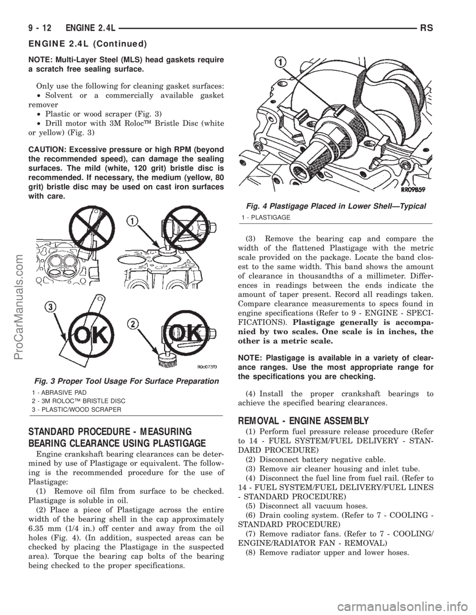
²Plastic or wood scraper (Fig. 3)
²Drill motor with 3M RolocŸ Bristle Disc (white
or yellow) (Fig. 3)
CAUTION: Excessive pressure or high RPM (beyond
the recommended speed), can damage the sealing
surfaces. The mild (white, 120 grit) bristle disc is
recommended. If necessary, the medium (yellow, 80
grit) bristle disc may be used on cast iron surfaces
with care.
STANDARD PROCEDURE - MEASURING
BEARING CLEARANCE USING PLASTIGAGE
Engine crankshaft bearing clearances can be deter-
mined by use of Plastigage or equivalent. The follow-
ing is the recommended procedure for the use of
Plastigage:
(1) Remove oil film from surface to be checked.
Plastigage is soluble in oil.
(2) Place a piece of Plastigage across the entire
width of the bearing shell in the cap approximately
6.35 mm (1/4 in.) off center and away from the oil
holes (Fig. 4). (In addition, suspected areas can be
checked by placing the Plastigage in the suspected
area). Torque the bearing cap bolts of the bearing
being checked to the proper specifications.(3) Remove the bearing cap and compare the
width of the flattened Plastigage with the metric
scale provided on the package. Locate the band clos-
est to the same width. This band shows the amount
of clearance in thousandths of a millimeter. Differ-
ences in readings between the ends indicate the
amount of taper present. Record all readings taken.
Compare clearance measurements to specs found in
engine specifications (Refer to 9 - ENGINE - SPECI-
FICATIONS).Plastigage generally is accompa-
nied by two scales. One scale is in inches, the
other is a metric scale.
NOTE: Plastigage is available in a variety of clear-
ance ranges. Use the most appropriate range for
the specifications you are checking.
(4) Install the proper crankshaft bearings to
achieve the specified bearing clearances.
REMOVAL - ENGINE ASSEMBLY
(1) Perform fuel pressure release procedure (Refer
to 14 - FUEL SYSTEM/FUEL DELIVERY - STAN-
DARD PROCEDURE)
(2) Disconnect battery negative cable.
(3) Remove air cleaner housing and inlet tube.
(4) Disconnect the fuel line from fuel rail. (Refer to
14 - FUEL SYSTEM/FUEL DELIVERY/FUEL LINES
- STANDARD PROCEDURE)
(5) Disconnect all vacuum hoses.
(6) Drain cooling system. (Refer to 7 - COOLING -
STANDARD PROCEDURE)
(7) Remove radiator fans. (Refer to 7 - COOLING/
ENGINE/RADIATOR FAN - REMOVAL)
(8) Remove radiator upper and lower hoses.
Fig. 3 Proper Tool Usage For Surface Preparation
1 - ABRASIVE PAD
2 - 3M ROLOCŸ BRISTLE DISC
3 - PLASTIC/WOOD SCRAPER
Fig. 4 Plastigage Placed in Lower ShellÐTypical
1 - PLASTIGAGE
9 - 12 ENGINE 2.4LRS
ENGINE 2.4L (Continued)
ProCarManuals.com
Page 1457 of 2399
INSTALLATION
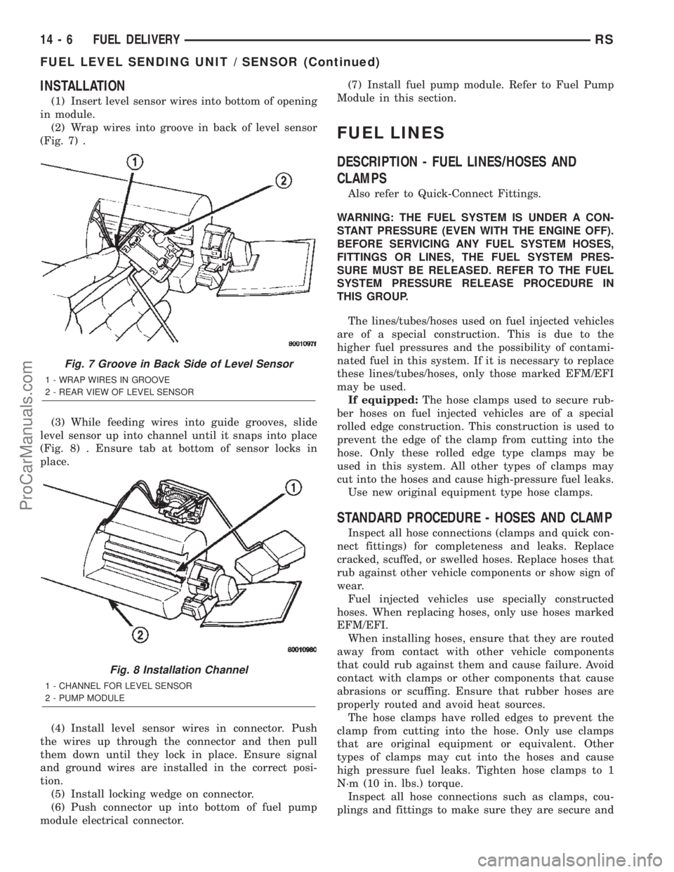
(1) Insert level sensor wires into bottom of opening
in module.
(2) Wrap wires into groove in back of level sensor
(Fig. 7) .
(3) While feeding wires into guide grooves, slide
level sensor up into channel until it snaps into place
(Fig. 8) . Ensure tab at bottom of sensor locks in
place.
(4) Install level sensor wires in connector. Push
the wires up through the connector and then pull
them down until they lock in place. Ensure signal
and ground wires are installed in the correct posi-
tion.
(5) Install locking wedge on connector.
(6) Push connector up into bottom of fuel pump
module electrical connector.(7) Install fuel pump module. Refer to Fuel Pump
Module in this section.
FUEL LINES
DESCRIPTION - FUEL LINES/HOSES AND
CLAMPS
Also refer to Quick-Connect Fittings.
WARNING: THE FUEL SYSTEM IS UNDER A CON-
STANT PRESSURE (EVEN WITH THE ENGINE OFF).
BEFORE SERVICING ANY FUEL SYSTEM HOSES,
FITTINGS OR LINES, THE FUEL SYSTEM PRES-
SURE MUST BE RELEASED. REFER TO THE FUEL
SYSTEM PRESSURE RELEASE PROCEDURE IN
THIS GROUP.
The lines/tubes/hoses used on fuel injected vehicles
are of a special construction. This is due to the
higher fuel pressures and the possibility of contami-
nated fuel in this system. If it is necessary to replace
these lines/tubes/hoses, only those marked EFM/EFI
may be used.
If equipped:The hose clamps used to secure rub-
ber hoses on fuel injected vehicles are of a special
rolled edge construction. This construction is used to
prevent the edge of the clamp from cutting into the
hose. Only these rolled edge type clamps may be
used in this system. All other types of clamps may
cut into the hoses and cause high-pressure fuel leaks.
Use new original equipment type hose clamps.
STANDARD PROCEDURE - HOSES AND CLAMP
Inspect all hose connections (clamps and quick con-
nect fittings) for completeness and leaks. Replace
cracked, scuffed, or swelled hoses. Replace hoses that
rub against other vehicle components or show sign of
wear.
Fuel injected vehicles use specially constructed
hoses. When replacing hoses, only use hoses marked
EFM/EFI.
When installing hoses, ensure that they are routed
away from contact with other vehicle components
that could rub against them and cause failure. Avoid
contact with clamps or other components that cause
abrasions or scuffing. Ensure that rubber hoses are
properly routed and avoid heat sources.
The hose clamps have rolled edges to prevent the
clamp from cutting into the hose. Only use clamps
that are original equipment or equivalent. Other
types of clamps may cut into the hoses and cause
high pressure fuel leaks. Tighten hose clamps to 1
N´m (10 in. lbs.) torque.
Inspect all hose connections such as clamps, cou-
plings and fittings to make sure they are secure and
Fig. 7 Groove in Back Side of Level Sensor
1 - WRAP WIRES IN GROOVE
2 - REAR VIEW OF LEVEL SENSOR
Fig. 8 Installation Channel
1 - CHANNEL FOR LEVEL SENSOR
2 - PUMP MODULE
14 - 6 FUEL DELIVERYRS
FUEL LEVEL SENDING UNIT / SENSOR (Continued)
ProCarManuals.com
Page 1488 of 2399
FUEL SYSTEM
TABLE OF CONTENTS
page page
FUEL SYSTEM 2.5L TURBO DIESEL
DESCRIPTION - DIESEL FUEL DELIVERY
SYSTEM.............................1
WARNING - HIGH FUEL SYSTEM PRESSURE . . 1
DIAGNOSIS AND TESTING
DIAGNOSIS AND TESTING - AIR IN FUEL
SYSTEM.............................1
DIAGNOSIS AND TESTING - FUEL SUPPLY
RESTRICTIONS........................1
STANDARD PROCEDURE
STANDARD PROCEDURES - DRAINING
WATER FROM FUEL FILTER..............2STANDARD PROCEDURE - FUEL SYSTEM
AIR PURGE...........................2
STANDARD PROCEDURES - CLEANING
FUEL SYSTEM COMPONENTS............2
SPECIFICATIONS - TORQUE...............3
FUEL DELIVERY..........................4
FUEL INJECTION........................11
FUEL SYSTEM 2.5L TURBO
DIESEL
DESCRIPTION - DIESEL FUEL DELIVERY
SYSTEM
The fuel system on the 2.5L Common Rail Diesel
Engine uses a fuel injection pump and an Electronic
Control Module (ECM).
The fuel delivery system consists of the:
²Accelerator pedal
²Air cleaner housing/element
²Fuel filter/water separator
²Fuel heater
²Fuel heater relay
²Fuel transfer (lift) pump
²Fuel injection pump
²Fuel injectors
²Fuel tank
²Fuel tank filler/vent tube assembly
²Fuel tank filler tube cap
²Fuel tank module containing the rollover valve
and a fuel gauge sending unit (fuel level sensor).
²Fuel tubes/lines/hoses
²High-pressure fuel injector lines
²Low-pressure fuel supply lines
²Low-pressure fuel return line
²Overflow valve
²Quick-connect fittings
²Water draining
WARNING - HIGH FUEL SYSTEM PRESSURE
WARNING:: THE INJECTION PUMP SUPPLIES HIGH-
PRESSURE FUEL TO EACH INDIVIDUAL INJECTOR
THROUGH HIGH-PRESSURE LINES. FUEL UNDERTHIS AMOUNT OF PRESSURE CAN PENETRATE
SKIN AND CAUSE PERSONAL INJURY. WEAR
SAFETY GOGGLES AND ADEQUATE PROTECTIVE
CLOTHING. AVOID CONTACT WITH FUEL SPRAY
WHEN BLEEDING HIGH-PRESSURE FUEL LINES.
DIAGNOSIS AND TESTING
DIAGNOSIS AND TESTING - AIR IN FUEL
SYSTEM
Air will enter the fuel system whenever fuel supply
lines, separator filters, injection pump, high-pressure
lines or injectors are removed or disconnected. Air
trapped in the fuel system can result in hard start-
ing, a rough running engine, engine misfire, low
power, excessive smoke and fuel knock. After service
is performed, air must be bled from the system
before starting the engine.
Inspect the fuel system from the fuel tank to the
injectors for loose connections. Leaking fuel is an
indicator of loose connections or defective seals. Air
can also enter the fuel system between the fuel tank
and the transfer pump. Inspect the fuel tank and fuel
lines for damage that might allow air into the sys-
tem.
DIAGNOSIS AND TESTING - FUEL SUPPLY
RESTRICTIONS
LOW-PRESSURE LINES
Fuel supply line restrictions or a defective fuel
transfer pump can cause starting problems and pre-
vent engine from accelerating. The starting problems
include; low power and/or white fog like exhaust.
RGFUEL SYSTEM14a-1
ProCarManuals.com
Page 1489 of 2399
Test all fuel supply lines for restrictions or block-
age. Flush or replace as necessary. Bleed fuel system
of air once a fuel supply line has been replaced. Refer
to Air Bleed Procedure for procedures.
To test for fuel line restrictions, a vacuum restric-
tion test may be performed.
HIGH-PRESSURE LINES
Restricted (kinked or bent) high-pressure lines can
cause starting problems, poor engine performance,
engine mis-fire and white smoke from exhaust.
Examine all high-pressure lines for any damage.
Each radius on each high-pressure line must be
smooth and free of any bends or kinks.
Replace damaged, restricted or leaking high-pres-
sure fuel lines with correct replacement line.
CAUTION: High pressure lines cannot contact each
other or other components. Do not attempt to weld
high-pressure fuel lines or to repair lines that are
damaged. If line is kinked or bent, it must be
replaced. Use only recommended lines when
replacement of high-pressure fuel line is necessary.
STANDARD PROCEDURE
STANDARD PROCEDURES - DRAINING WATER
FROM FUEL FILTER
Refer to Fuel Filter/Water Separator removal/in-
stallation for procedures.
STANDARD PROCEDURE - FUEL SYSTEM AIR
PURGE
(1) Remove engine cover (Refer to 9 - ENGINE
COVER - REMOVAL).
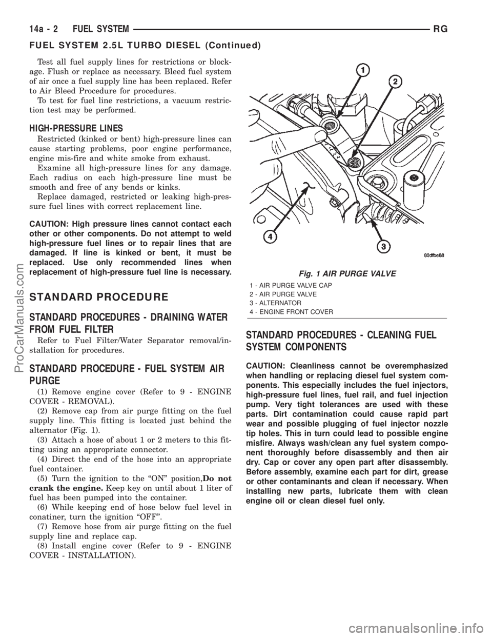
(2) Remove cap from air purge fitting on the fuel
supply line. This fitting is located just behind the
alternator (Fig. 1).
(3) Attach a hose of about 1 or 2 meters to this fit-
ting using an appropriate connector.
(4) Direct the end of the hose into an appropriate
fuel container.
(5) Turn the ignition to the ªONº position,Do not
crank the engine.Keep key on until about 1 liter of
fuel has been pumped into the container.
(6) While keeping end of hose below fuel level in
conatiner, turn the ignition ªOFFº.
(7) Remove hose from air purge fitting on the fuel
supply line and replace cap.
(8) Install engine cover (Refer to 9 - ENGINE
COVER - INSTALLATION).
STANDARD PROCEDURES - CLEANING FUEL
SYSTEM COMPONENTS
CAUTION: Cleanliness cannot be overemphasized
when handling or replacing diesel fuel system com-
ponents. This especially includes the fuel injectors,
high-pressure fuel lines, fuel rail, and fuel injection
pump. Very tight tolerances are used with these
parts. Dirt contamination could cause rapid part
wear and possible plugging of fuel injector nozzle
tip holes. This in turn could lead to possible engine
misfire. Always wash/clean any fuel system compo-
nent thoroughly before disassembly and then air
dry. Cap or cover any open part after disassembly.
Before assembly, examine each part for dirt, grease
or other contaminants and clean if necessary. When
installing new parts, lubricate them with clean
engine oil or clean diesel fuel only.
Fig. 1 AIR PURGE VALVE
1 - AIR PURGE VALVE CAP
2 - AIR PURGE VALVE
3 - ALTERNATOR
4 - ENGINE FRONT COVER
14a - 2 FUEL SYSTEMRG
FUEL SYSTEM 2.5L TURBO DIESEL (Continued)
ProCarManuals.com