2002 CHRYSLER CARAVAN transmission oil
[x] Cancel search: transmission oilPage 1583 of 2399
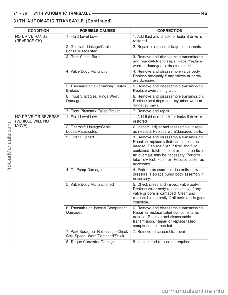
CONDITION POSSIBLE CAUSES CORRECTION
NO DRIVE RANGE
(REVERSE OK)1. Fluid Level Low. 1. Add fluid and check for leaks if drive is
restored.
2. Gearshift Linkage/Cable
Loose/Misadjusted.2. Repair or replace linkage components.
3. Rear Clutch Burnt. 3. Remove and disassemble transmission
and rear clutch and seals. Repair/replace
worn or damaged parts as needed.
4. Valve Body Malfunction. 4. Remove and disassemble valve body.
Replace assembly if any valves or bores
are damaged.
5. Transmission Overrunning Clutch
Broken.5. Remove and disassemble transmission.
Replace overrunning clutch.
6. Input Shaft Seal Rings Worn/
Damaged.6. Remove and disassemble transmission.
Replace seal rings and any other worn or
damaged parts.
7. Front Planetary Failed Broken. 7. Remove and repair.
NO DRIVE OR REVERSE
(VEHICLE WILL NOT
MOVE)1. Fluid Level Low. 1. Add fluid and check for leaks if drive is
restored.
2. Gearshift Linkage/Cable
Loose/Misadjusted.2. Inspect, adjust and reassemble linkage
as needed. Replace worn/damaged parts.
3. Filter Plugged. 3. Remove and disassemble transmission.
Repair or replace failed components as
needed. Replace filter. If filter and fluid
contained clutch material or metal particles,
an overhaul may be necessary. Perform
lube flow test. Flush oil. Replace cooler as
necessary.
4. Oil Pump Damaged. 4. Perform pressure test to confirm low
pressure. Replace pump body assembly if
necessary.
5. Valve Body Malfunctioned. 5. Check press and inspect valve body.
Replace valve body (as assembly) if any
valve or bore is damaged. Clean and
reassemble correctly if all parts are in good
condition.
6. Transmission Internal Component
Damaged.6. Remove and disassemble transmission.
Repair or replace failed components as
needed. Remove and disassemble
transmission. Repair or replace failed
components as needed.
7. Park Sprag not Releasing - Check
Stall Speed, Worn/Damaged/Stuck.7. Remove, disassemble, repair.
8. Torque Converter Damage. 8. Inspect and replace as required.
21 - 26 31TH AUTOMATIC TRANSAXLERS
31TH AUTOMATIC TRANSAXLE (Continued)
ProCarManuals.com
Page 1592 of 2399
DIAGNOSIS AND TESTING - TORQUE
CONVERTER HOUSING FLUID LEAKAGE
When diagnosing converter housing fluid leaks,
three actions must be taken before repair:
(1) Verify proper transmission fluid level.
(2) Verify that the leak originates from the con-
verter housing area and is transmission fluid.
(3) Determine the true source of the leak.
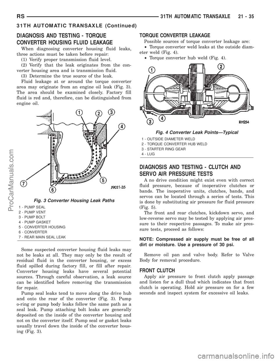
Fluid leakage at or around the torque converter
area may originate from an engine oil leak (Fig. 3).
The area should be examined closely. Factory fill
fluid is red and, therefore, can be distinguished from
engine oil.
Some suspected converter housing fluid leaks may
not be leaks at all. They may only be the result of
residual fluid in the converter housing, or excess
fluid spilled during factory fill, or fill after repair.
Converter housing leaks have several potential
sources. Through careful observation, a leak source
can be identified before removing the transmission
for repair.
Pump seal leaks tend to move along the drive hub
and onto the rear of the converter (Fig. 3). Pump
o-ring or pump body leaks follow the same path as a
seal leak. Pump attaching bolt leaks are generally
deposited on the inside of the converter housing and
not on the converter itself. Pump seal or gasket leaks
usually travel down the inside of the converter hous-
ing (Fig. 3).
TORQUE CONVERTER LEAKAGE
Possible sources of torque converter leakage are:
²Torque converter weld leaks at the outside diam-
eter weld (Fig. 4).
²Torque converter hub weld (Fig. 4).
DIAGNOSIS AND TESTING - CLUTCH AND
SERVO AIR PRESSURE TESTS
A no drive condition might exist even with correct
fluid pressure, because of inoperative clutches or
bands. The inoperative units, clutches, bands, and
servos can be located through a series of tests. This
is done by substituting air pressure for fluid pressure
(Fig. 5).
The front and rear clutches, kickdown servo, and
low-reverse servo may be tested by applying air pres-
sure to their respective passages. To make air pres-
sure tests, proceed as follows:
NOTE: Compressed air supply must be free of all
dirt or moisture. Use a pressure of 30 psi.
Remove oil pan and valve body. Refer to Valve
Body for removal procedure.
FRONT CLUTCH
Apply air pressure to front clutch apply passage
and listen for a dull thud which indicates that front
clutch is operating. Hold air pressure on for a few
seconds and inspect system for excessive oil leaks.
Fig. 3 Converter Housing Leak Paths
1 - PUMP SEAL
2 - PUMP VENT
3 - PUMP BOLT
4 - PUMP GASKET
5 - CONVERTER HOUSING
6 - CONVERTER
7 - REAR MAIN SEAL LEAK
Fig. 4 Converter Leak PointsÐTypical
1 - OUTSIDE DIAMETER WELD
2 - TORQUE CONVERTER HUB WELD
3 - STARTER RING GEAR
4 - LUG
RS31TH AUTOMATIC TRANSAXLE21-35
31TH AUTOMATIC TRANSAXLE (Continued)
ProCarManuals.com
Page 1597 of 2399
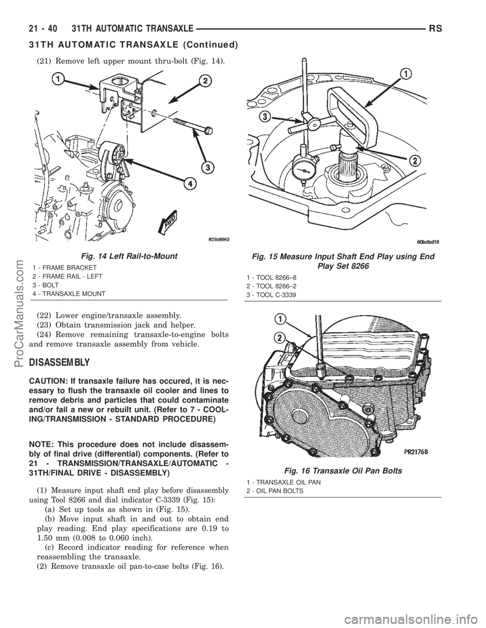
(21) Remove left upper mount thru-bolt (Fig. 14).
(22) Lower engine/transaxle assembly.
(23) Obtain transmission jack and helper.
(24) Remove remaining transaxle-to-engine bolts
and remove transaxle assembly from vehicle.
DISASSEMBLY
CAUTION: If transaxle failure has occured, it is nec-
essary to flush the transaxle oil cooler and lines to
remove debris and particles that could contaminate
and/or fail a new or rebuilt unit. (Refer to 7 - COOL-
ING/TRANSMISSION - STANDARD PROCEDURE)
NOTE: This procedure does not include disassem-
bly of final drive (differential) components. (Refer to
21 - TRANSMISSION/TRANSAXLE/AUTOMATIC -
31TH/FINAL DRIVE - DISASSEMBLY)
(1)
Measure input shaft end play before disassembly
using Tool 8266 and dial indicator C-3339 (Fig. 15):
(a) Set up tools as shown in (Fig. 15).
(b) Move input shaft in and out to obtain end
play reading. End play specifications are 0.19 to
1.50 mm (0.008 to 0.060 inch).
(c) Record indicator reading for reference when
reassembling the transaxle.
(2)
Remove transaxle oil pan-to-case bolts (Fig. 16).
Fig. 14 Left Rail-to-Mount
1 - FRAME BRACKET
2 - FRAME RAIL - LEFT
3 - BOLT
4 - TRANSAXLE MOUNT
Fig. 15 Measure Input Shaft End Play using End
Play Set 8266
1 - TOOL 8266±8
2 - TOOL 8266±2
3 - TOOL C-3339
Fig. 16 Transaxle Oil Pan Bolts
1 - TRANSAXLE OIL PAN
2 - OIL PAN BOLTS
21 - 40 31TH AUTOMATIC TRANSAXLERS
31TH AUTOMATIC TRANSAXLE (Continued)
ProCarManuals.com
Page 1603 of 2399
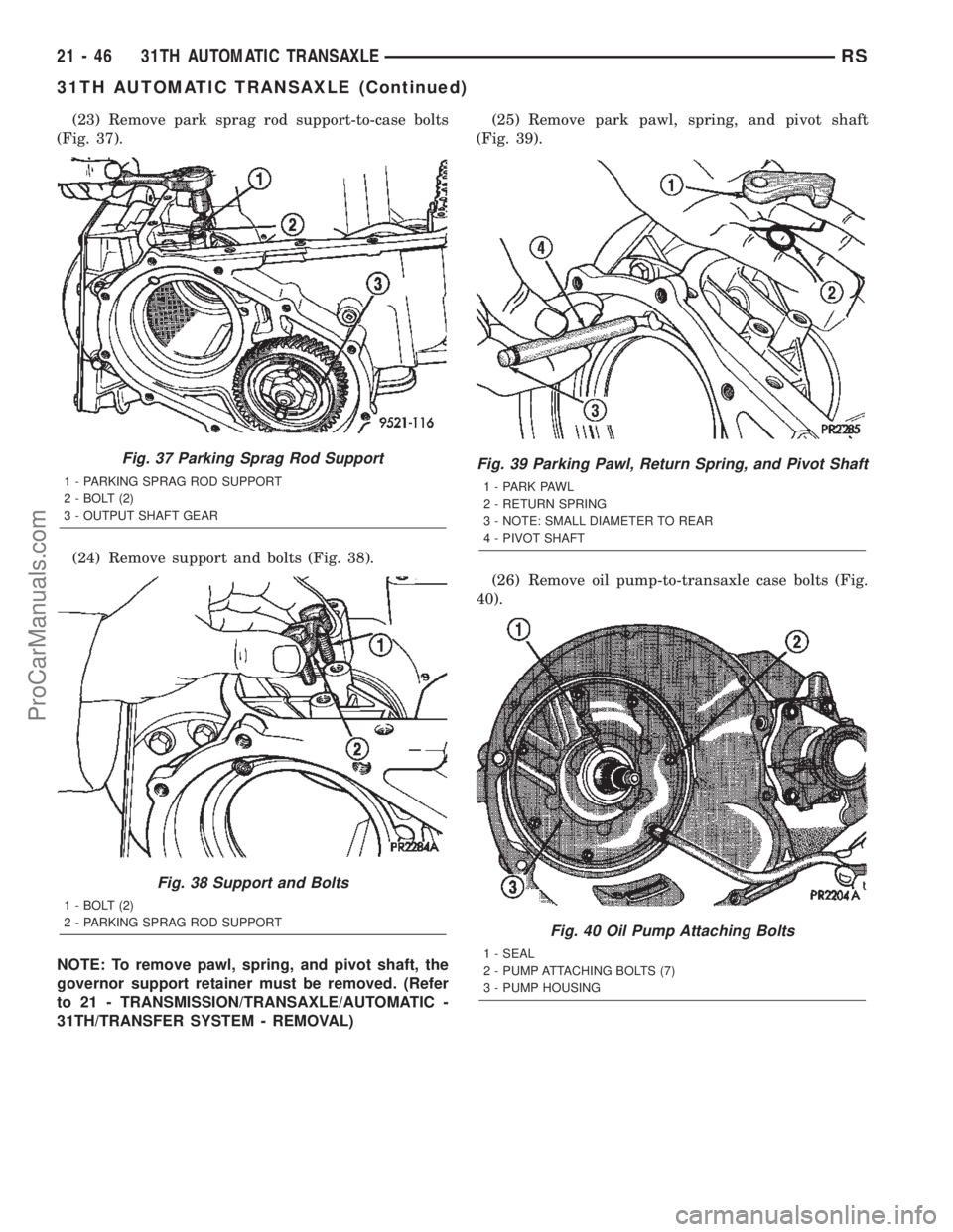
(23) Remove park sprag rod support-to-case bolts
(Fig. 37).
(24) Remove support and bolts (Fig. 38).
NOTE: To remove pawl, spring, and pivot shaft, the
governor support retainer must be removed. (Refer
to 21 - TRANSMISSION/TRANSAXLE/AUTOMATIC -
31TH/TRANSFER SYSTEM - REMOVAL)(25) Remove park pawl, spring, and pivot shaft
(Fig. 39).
(26) Remove oil pump-to-transaxle case bolts (Fig.
40).
Fig. 37 Parking Sprag Rod Support
1 - PARKING SPRAG ROD SUPPORT
2 - BOLT (2)
3 - OUTPUT SHAFT GEAR
Fig. 38 Support and Bolts
1 - BOLT (2)
2 - PARKING SPRAG ROD SUPPORT
Fig. 39 Parking Pawl, Return Spring, and Pivot Shaft
1 - PARK PAWL
2 - RETURN SPRING
3 - NOTE: SMALL DIAMETER TO REAR
4 - PIVOT SHAFT
Fig. 40 Oil Pump Attaching Bolts
1 - SEAL
2 - PUMP ATTACHING BOLTS (7)
3 - PUMP HOUSING
21 - 46 31TH AUTOMATIC TRANSAXLERS
31TH AUTOMATIC TRANSAXLE (Continued)
ProCarManuals.com
Page 1608 of 2399
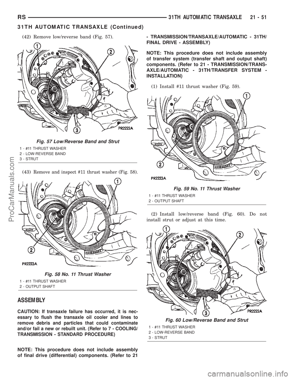
(42) Remove low/reverse band (Fig. 57).
(43)
Remove and inspect #11 thrust washer (Fig. 58).
ASSEMBLY
CAUTION: If transaxle failure has occurred, it is nec-
essary to flush the transaxle oil cooler and lines to
remove debris and particles that could contaminate
and/or fail a new or rebuilt unit. (Refer to 7 - COOLING/
TRANSMISSION - STANDARD PROCEDURE)
NOTE: This procedure does not include assembly
of final drive (differential) components. (Refer to 21- TRANSMISSION/TRANSAXLE/AUTOMATIC - 31TH/
FINAL DRIVE - ASSEMBLY)
NOTE: This procedure does not include assembly
of transfer system (transfer shaft and output shaft)
components. (Refer to 21 - TRANSMISSION/TRANS-
AXLE/AUTOMATIC - 31TH/TRANSFER SYSTEM -
INSTALLATION)
(1) Install #11 thrust washer (Fig. 59).
(2) Install low/reverse band (Fig. 60). Do not
install strut or adjust at this time.
Fig. 57 Low/Reverse Band and Strut
1 - #11 THRUST WASHER
2 - LOW-REVERSE BAND
3 - STRUT
Fig. 58 No. 11 Thrust Washer
1 - #11 THRUST WASHER
2 - OUTPUT SHAFT
Fig. 59 No. 11 Thrust Washer
1 - #11 THRUST WASHER
2 - OUTPUT SHAFT
Fig. 60 Low/Reverse Band and Strut
1 - #11 THRUST WASHER
2 - LOW-REVERSE BAND
3 - STRUT
RS31TH AUTOMATIC TRANSAXLE21-51
31TH AUTOMATIC TRANSAXLE (Continued)
ProCarManuals.com
Page 1637 of 2399
BANDS
DESCRIPTION
KICKDOWN (FRONT) BAND
DESCRIPTION
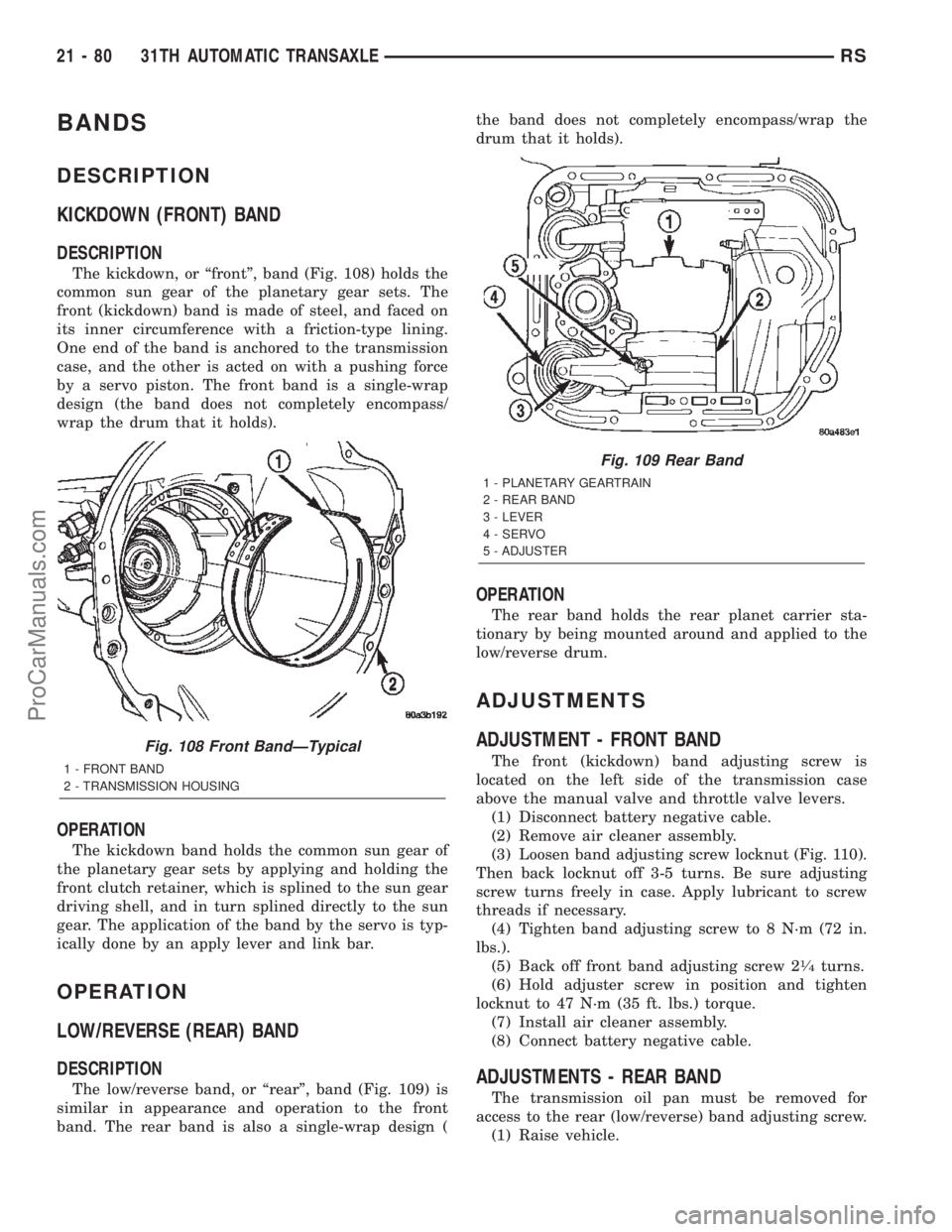
The kickdown, or ªfrontº, band (Fig. 108) holds the
common sun gear of the planetary gear sets. The
front (kickdown) band is made of steel, and faced on
its inner circumference with a friction-type lining.
One end of the band is anchored to the transmission
case, and the other is acted on with a pushing force
by a servo piston. The front band is a single-wrap
design (the band does not completely encompass/
wrap the drum that it holds).
OPERATION
The kickdown band holds the common sun gear of
the planetary gear sets by applying and holding the
front clutch retainer, which is splined to the sun gear
driving shell, and in turn splined directly to the sun
gear. The application of the band by the servo is typ-
ically done by an apply lever and link bar.
OPERATION
LOW/REVERSE (REAR) BAND
DESCRIPTION
The low/reverse band, or ªrearº, band (Fig. 109) is
similar in appearance and operation to the front
band. The rear band is also a single-wrap design (the band does not completely encompass/wrap the
drum that it holds).
OPERATION
The rear band holds the rear planet carrier sta-
tionary by being mounted around and applied to the
low/reverse drum.
ADJUSTMENTS
ADJUSTMENT - FRONT BAND
The front (kickdown) band adjusting screw is
located on the left side of the transmission case
above the manual valve and throttle valve levers.
(1) Disconnect battery negative cable.
(2) Remove air cleaner assembly.
(3) Loosen band adjusting screw locknut (Fig. 110).
Then back locknut off 3-5 turns. Be sure adjusting
screw turns freely in case. Apply lubricant to screw
threads if necessary.
(4) Tighten band adjusting screw to 8 N´m (72 in.
lbs.).
(5) Back off front band adjusting screw 2
1¤4turns.
(6) Hold adjuster screw in position and tighten
locknut to 47 N´m (35 ft. lbs.) torque.
(7) Install air cleaner assembly.
(8) Connect battery negative cable.
ADJUSTMENTS - REAR BAND
The transmission oil pan must be removed for
access to the rear (low/reverse) band adjusting screw.
(1) Raise vehicle.
Fig. 108 Front BandÐTypical
1 - FRONT BAND
2 - TRANSMISSION HOUSING
Fig. 109 Rear Band
1 - PLANETARY GEARTRAIN
2 - REAR BAND
3 - LEVER
4 - SERVO
5 - ADJUSTER
21 - 80 31TH AUTOMATIC TRANSAXLERS
ProCarManuals.com
Page 1638 of 2399
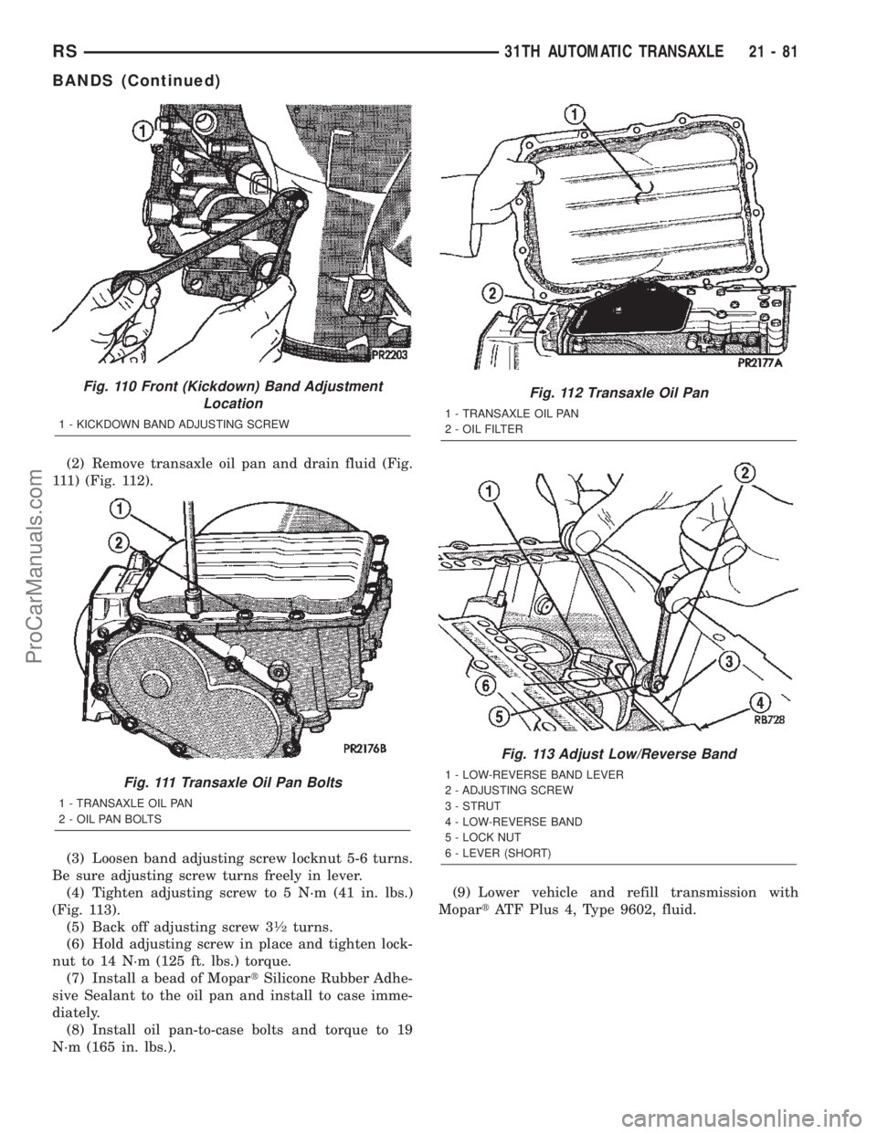
(2) Remove transaxle oil pan and drain fluid (Fig.
111) (Fig. 112).
(3) Loosen band adjusting screw locknut 5-6 turns.
Be sure adjusting screw turns freely in lever.
(4) Tighten adjusting screw to 5 N´m (41 in. lbs.)
(Fig. 113).
(5) Back off adjusting screw 3
1¤2turns.
(6) Hold adjusting screw in place and tighten lock-
nut to 14 N´m (125 ft. lbs.) torque.
(7) Install a bead of MopartSilicone Rubber Adhe-
sive Sealant to the oil pan and install to case imme-
diately.
(8) Install oil pan-to-case bolts and torque to 19
N´m (165 in. lbs.).(9) Lower vehicle and refill transmission with
MopartATF Plus 4, Type 9602, fluid.
Fig. 110 Front (Kickdown) Band Adjustment
Location
1 - KICKDOWN BAND ADJUSTING SCREW
Fig. 111 Transaxle Oil Pan Bolts
1 - TRANSAXLE OIL PAN
2 - OIL PAN BOLTS
Fig. 112 Transaxle Oil Pan
1 - TRANSAXLE OIL PAN
2 - OIL FILTER
Fig. 113 Adjust Low/Reverse Band
1 - LOW-REVERSE BAND LEVER
2 - ADJUSTING SCREW
3 - STRUT
4 - LOW-REVERSE BAND
5 - LOCK NUT
6 - LEVER (SHORT)
RS31TH AUTOMATIC TRANSAXLE21-81
BANDS (Continued)
ProCarManuals.com
Page 1639 of 2399
CLUTCH - FRONT
DESCRIPTION
The front clutch assembly (Fig. 119) is composed of
the front clutch retainer, pressure plate, clutch
plates, driving discs, piston, piston return spring,
return spring retainer, and snap-rings. The front
clutch is the forward-most component in the trans-
mission geartrain and is directly behind the oil
pump. It is considered a driving component.
NOTE: The number of discs and plates may vary
with each engine and vehicle combination.
OPERATION
To apply the clutch, pressure is applied between
the clutch retainer and piston. The fluid pressure is
provided by the oil pump, transferred through the
control valves and passageways, and enters the
clutch through the hub of the reaction shaft support.
With pressure applied between the clutch retainer
and piston, the piston moves away from the clutch
retainer and compresses the clutch pack. This action
applies the clutch pack, allowing torque to flow
through the input shaft into the driving discs, and
into the clutch plates and pressure plate that are
lugged to the clutch retainer. The waved snap-ring is
used to cushion the application of the clutch pack. In
some transmissions, the snap-ring is selective and
used to adjust clutch pack clearance.
When pressure is released from the piston, the
spring returns the piston to its fully released position
and disengages the clutch. The release spring also
helps to cushion the application of the clutch assem-
bly. When the clutch is in the process of being
released by the release spring, fluid flows through a
vent and one-way ball-check-valve located in the
clutch retainer. The check-valve is needed to elimi-
nate the possibility of plate drag caused by centrifu-
gal force acting on the residual fluid trapped in the
clutch piston retainer.
DISASSEMBLY
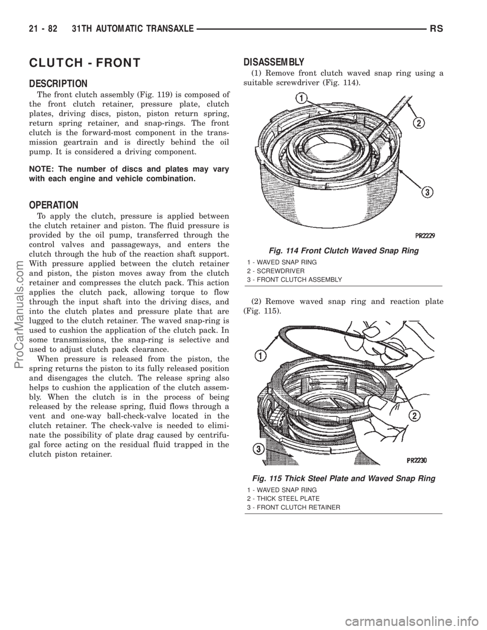
(1) Remove front clutch waved snap ring using a
suitable screwdriver (Fig. 114).
(2) Remove waved snap ring and reaction plate
(Fig. 115).
Fig. 114 Front Clutch Waved Snap Ring
1 - WAVED SNAP RING
2 - SCREWDRIVER
3 - FRONT CLUTCH ASSEMBLY
Fig. 115 Thick Steel Plate and Waved Snap Ring
1 - WAVED SNAP RING
2 - THICK STEEL PLATE
3 - FRONT CLUTCH RETAINER
21 - 82 31TH AUTOMATIC TRANSAXLERS
ProCarManuals.com