2002 CHRYSLER CARAVAN transmission oil
[x] Cancel search: transmission oilPage 1217 of 2399
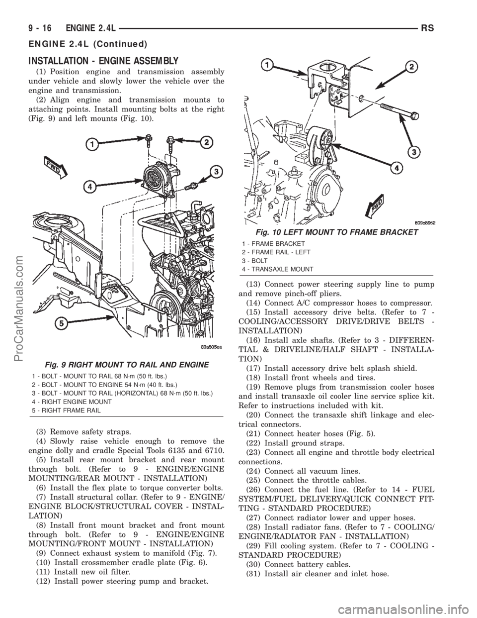
INSTALLATION - ENGINE ASSEMBLY
(1) Position engine and transmission assembly
under vehicle and slowly lower the vehicle over the
engine and transmission.
(2) Align engine and transmission mounts to
attaching points. Install mounting bolts at the right
(Fig. 9) and left mounts (Fig. 10).
(3) Remove safety straps.
(4) Slowly raise vehicle enough to remove the
engine dolly and cradle Special Tools 6135 and 6710.
(5) Install rear mount bracket and rear mount
through bolt. (Refer to 9 - ENGINE/ENGINE
MOUNTING/REAR MOUNT - INSTALLATION)
(6) Install the flex plate to torque converter bolts.
(7) Install structural collar. (Refer to 9 - ENGINE/
ENGINE BLOCK/STRUCTURAL COVER - INSTAL-
LATION)
(8) Install front mount bracket and front mount
through bolt. (Refer to 9 - ENGINE/ENGINE
MOUNTING/FRONT MOUNT - INSTALLATION)
(9) Connect exhaust system to manifold (Fig. 7).
(10) Install crossmember cradle plate (Fig. 6).
(11) Install new oil filter.
(12) Install power steering pump and bracket.(13) Connect power steering supply line to pump
and remove pinch-off pliers.
(14) Connect A/C compressor hoses to compressor.
(15) Install accessory drive belts. (Refer to 7 -
COOLING/ACCESSORY DRIVE/DRIVE BELTS -
INSTALLATION)
(16) Install axle shafts. (Refer to 3 - DIFFEREN-
TIAL & DRIVELINE/HALF SHAFT - INSTALLA-
TION)
(17) Install accessory drive belt splash shield.
(18) Install front wheels and tires.
(19) Remove plugs from transmission cooler hoses
and install transaxle oil cooler line service splice kit.
Refer to instructions included with kit.
(20) Connect the transaxle shift linkage and elec-
trical connectors.
(21) Connect heater hoses (Fig. 5).
(22) Install ground straps.
(23) Connect all engine and throttle body electrical
connections.
(24) Connect all vacuum lines.
(25) Connect the throttle cables.
(26) Connect the fuel line. (Refer to 14 - FUEL
SYSTEM/FUEL DELIVERY/QUICK CONNECT FIT-
TING - STANDARD PROCEDURE)
(27) Connect radiator lower and upper hoses.
(28) Install radiator fans. (Refer to 7 - COOLING/
ENGINE/RADIATOR FAN - INSTALLATION)
(29) Fill cooling system. (Refer to 7 - COOLING -
STANDARD PROCEDURE)
(30) Connect battery cables.
(31) Install air cleaner and inlet hose.
Fig. 9 RIGHT MOUNT TO RAIL AND ENGINE
1 - BOLT - MOUNT TO RAIL 68 N´m (50 ft. lbs.)
2 - BOLT - MOUNT TO ENGINE 54 N´m (40 ft. lbs.)
3 - BOLT - MOUNT TO RAIL (HORIZONTAL) 68 N´m (50 ft. lbs.)
4 - RIGHT ENGINE MOUNT
5 - RIGHT FRAME RAIL
Fig. 10 LEFT MOUNT TO FRAME BRACKET
1 - FRAME BRACKET
2 - FRAME RAIL - LEFT
3 - BOLT
4 - TRANSAXLE MOUNT
9 - 16 ENGINE 2.4LRS
ENGINE 2.4L (Continued)
ProCarManuals.com
Page 1218 of 2399
(32) Fill engine crankcase with proper oil to cor-
rect level.
(33) Start engine and run until operating temper-
ature is reached.
(34) Adjust transmission linkage, if necessary.
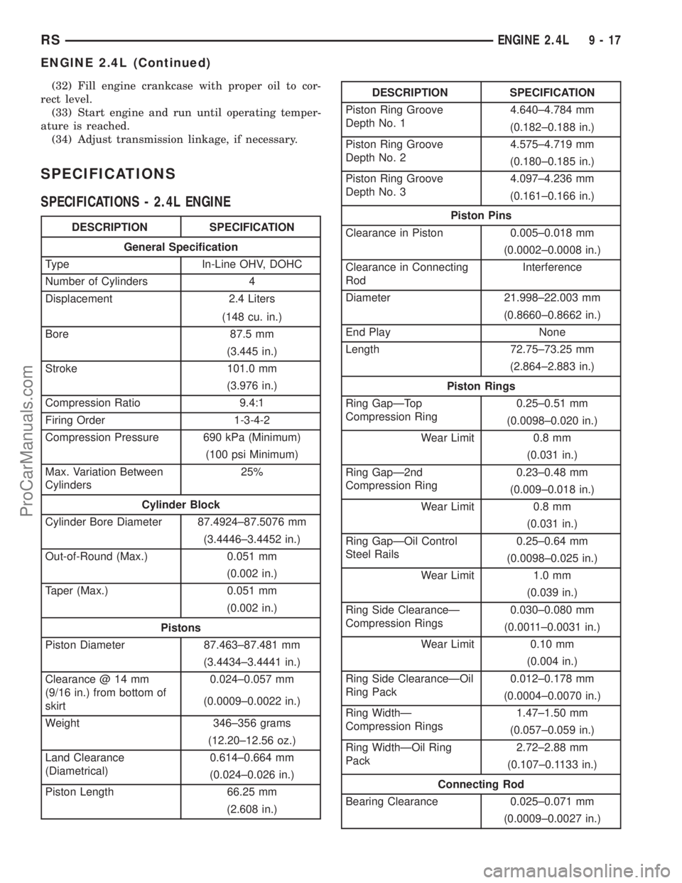
SPECIFICATIONS
SPECIFICATIONS - 2.4L ENGINE
DESCRIPTION SPECIFICATION
General Specification
Type In-Line OHV, DOHC
Number of Cylinders 4
Displacement 2.4 Liters
(148 cu. in.)
Bore 87.5 mm
(3.445 in.)
Stroke 101.0 mm
(3.976 in.)
Compression Ratio 9.4:1
Firing Order 1-3-4-2
Compression Pressure 690 kPa (Minimum)
(100 psi Minimum)
Max. Variation Between
Cylinders25%
Cylinder Block
Cylinder Bore Diameter 87.4924±87.5076 mm
(3.4446±3.4452 in.)
Out-of-Round (Max.) 0.051 mm
(0.002 in.)
Taper (Max.) 0.051 mm
(0.002 in.)
Pistons
Piston Diameter 87.463±87.481 mm
(3.4434±3.4441 in.)
Clearance @ 14 mm
(9/16 in.) from bottom of
skirt0.024±0.057 mm
(0.0009±0.0022 in.)
Weight 346±356 grams
(12.20±12.56 oz.)
Land Clearance
(Diametrical)0.614±0.664 mm
(0.024±0.026 in.)
Piston Length 66.25 mm
(2.608 in.)
DESCRIPTION SPECIFICATION
Piston Ring Groove
Depth No. 14.640±4.784 mm
(0.182±0.188 in.)
Piston Ring Groove
Depth No. 24.575±4.719 mm
(0.180±0.185 in.)
Piston Ring Groove
Depth No. 34.097±4.236 mm
(0.161±0.166 in.)
Piston Pins
Clearance in Piston 0.005±0.018 mm
(0.0002±0.0008 in.)
Clearance in Connecting
RodInterference
Diameter 21.998±22.003 mm
(0.8660±0.8662 in.)
End Play None
Length 72.75±73.25 mm
(2.864±2.883 in.)
Piston Rings
Ring GapÐTop
Compression Ring0.25±0.51 mm
(0.0098±0.020 in.)
Wear Limit 0.8 mm
(0.031 in.)
Ring GapÐ2nd
Compression Ring0.23±0.48 mm
(0.009±0.018 in.)
Wear Limit 0.8 mm
(0.031 in.)
Ring GapÐOil Control
Steel Rails0.25±0.64 mm
(0.0098±0.025 in.)
Wear Limit 1.0 mm
(0.039 in.)
Ring Side ClearanceÐ
Compression Rings0.030±0.080 mm
(0.0011±0.0031 in.)
Wear Limit 0.10 mm
(0.004 in.)
Ring Side ClearanceÐOil
Ring Pack0.012±0.178 mm
(0.0004±0.0070 in.)
Ring WidthÐ
Compression Rings1.47±1.50 mm
(0.057±0.059 in.)
Ring WidthÐOil Ring
Pack2.72±2.88 mm
(0.107±0.1133 in.)
Connecting Rod
Bearing Clearance 0.025±0.071 mm
(0.0009±0.0027 in.)
RSENGINE 2.4L9-17
ENGINE 2.4L (Continued)
ProCarManuals.com
Page 1237 of 2399
STANDARD PROCEDURE
STANDARD PROCEDURE - PISTON TO
CYLINDER BORE FITTING
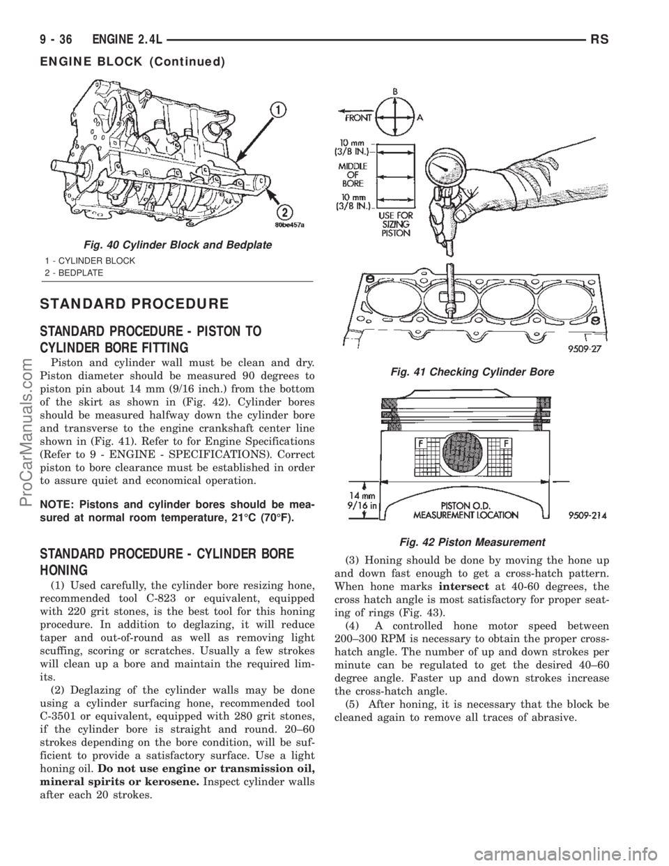
Piston and cylinder wall must be clean and dry.
Piston diameter should be measured 90 degrees to
piston pin about 14 mm (9/16 inch.) from the bottom
of the skirt as shown in (Fig. 42). Cylinder bores
should be measured halfway down the cylinder bore
and transverse to the engine crankshaft center line
shown in (Fig. 41). Refer to for Engine Specifications
(Refer to 9 - ENGINE - SPECIFICATIONS). Correct
piston to bore clearance must be established in order
to assure quiet and economical operation.
NOTE: Pistons and cylinder bores should be mea-
sured at normal room temperature, 21ÉC (70ÉF).
STANDARD PROCEDURE - CYLINDER BORE
HONING
(1) Used carefully, the cylinder bore resizing hone,
recommended tool C-823 or equivalent, equipped
with 220 grit stones, is the best tool for this honing
procedure. In addition to deglazing, it will reduce
taper and out-of-round as well as removing light
scuffing, scoring or scratches. Usually a few strokes
will clean up a bore and maintain the required lim-
its.
(2) Deglazing of the cylinder walls may be done
using a cylinder surfacing hone, recommended tool
C-3501 or equivalent, equipped with 280 grit stones,
if the cylinder bore is straight and round. 20±60
strokes depending on the bore condition, will be suf-
ficient to provide a satisfactory surface. Use a light
honing oil.Do not use engine or transmission oil,
mineral spirits or kerosene.Inspect cylinder walls
after each 20 strokes.(3) Honing should be done by moving the hone up
and down fast enough to get a cross-hatch pattern.
When hone marksintersectat 40-60 degrees, the
cross hatch angle is most satisfactory for proper seat-
ing of rings (Fig. 43).
(4) A controlled hone motor speed between
200±300 RPM is necessary to obtain the proper cross-
hatch angle. The number of up and down strokes per
minute can be regulated to get the desired 40±60
degree angle. Faster up and down strokes increase
the cross-hatch angle.
(5) After honing, it is necessary that the block be
cleaned again to remove all traces of abrasive.
Fig. 40 Cylinder Block and Bedplate
1 - CYLINDER BLOCK
2 - BEDPLATE
Fig. 41 Checking Cylinder Bore
Fig. 42 Piston Measurement
9 - 36 ENGINE 2.4LRS
ENGINE BLOCK (Continued)
ProCarManuals.com
Page 1244 of 2399
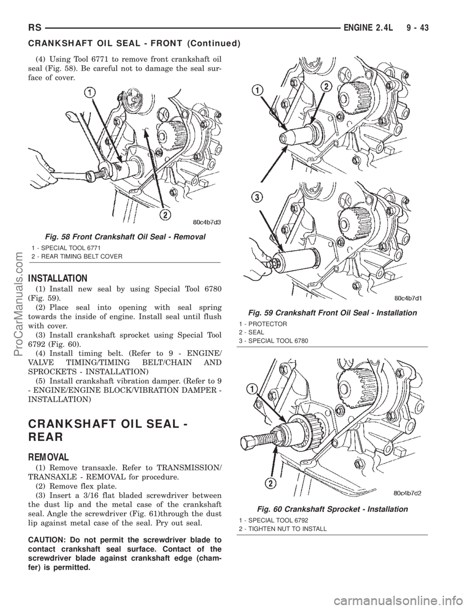
(4) Using Tool 6771 to remove front crankshaft oil
seal (Fig. 58). Be careful not to damage the seal sur-
face of cover.
INSTALLATION
(1) Install new seal by using Special Tool 6780
(Fig. 59).
(2) Place seal into opening with seal spring
towards the inside of engine. Install seal until flush
with cover.
(3) Install crankshaft sprocket using Special Tool
6792 (Fig. 60).
(4) Install timing belt. (Refer to 9 - ENGINE/
VALVE TIMING/TIMING BELT/CHAIN AND
SPROCKETS - INSTALLATION)
(5) Install crankshaft vibration damper. (Refer to 9
- ENGINE/ENGINE BLOCK/VIBRATION DAMPER -
INSTALLATION)
CRANKSHAFT OIL SEAL -
REAR
REMOVAL
(1) Remove transaxle. Refer to TRANSMISSION/
TRANSAXLE - REMOVAL for procedure.
(2) Remove flex plate.
(3) Insert a 3/16 flat bladed screwdriver between
the dust lip and the metal case of the crankshaft
seal. Angle the screwdriver (Fig. 61)through the dust
lip against metal case of the seal. Pry out seal.
CAUTION: Do not permit the screwdriver blade to
contact crankshaft seal surface. Contact of the
screwdriver blade against crankshaft edge (cham-
fer) is permitted.
Fig. 58 Front Crankshaft Oil Seal - Removal
1 - SPECIAL TOOL 6771
2 - REAR TIMING BELT COVER
Fig. 59 Crankshaft Front Oil Seal - Installation
1 - PROTECTOR
2 - SEAL
3 - SPECIAL TOOL 6780
Fig. 60 Crankshaft Sprocket - Installation
1 - SPECIAL TOOL 6792
2 - TIGHTEN NUT TO INSTALL
RSENGINE 2.4L9-43
CRANKSHAFT OIL SEAL - FRONT (Continued)
ProCarManuals.com
Page 1246 of 2399
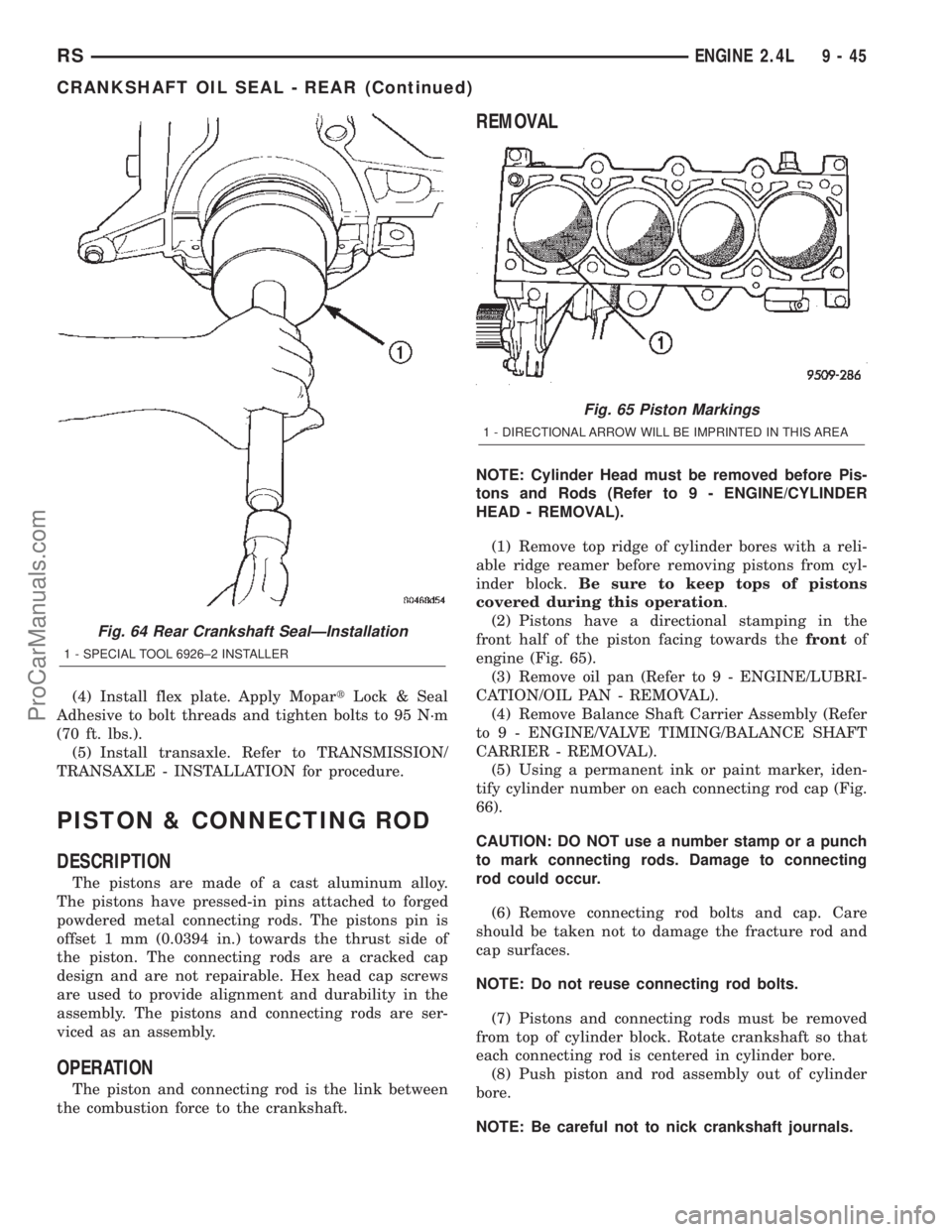
(4) Install flex plate. Apply MopartLock & Seal
Adhesive to bolt threads and tighten bolts to 95 N´m
(70 ft. lbs.).
(5) Install transaxle. Refer to TRANSMISSION/
TRANSAXLE - INSTALLATION for procedure.
PISTON & CONNECTING ROD
DESCRIPTION
The pistons are made of a cast aluminum alloy.
The pistons have pressed-in pins attached to forged
powdered metal connecting rods. The pistons pin is
offset 1 mm (0.0394 in.) towards the thrust side of
the piston. The connecting rods are a cracked cap
design and are not repairable. Hex head cap screws
are used to provide alignment and durability in the
assembly. The pistons and connecting rods are ser-
viced as an assembly.
OPERATION
The piston and connecting rod is the link between
the combustion force to the crankshaft.
REMOVAL
NOTE: Cylinder Head must be removed before Pis-
tons and Rods (Refer to 9 - ENGINE/CYLINDER
HEAD - REMOVAL).
(1) Remove top ridge of cylinder bores with a reli-
able ridge reamer before removing pistons from cyl-
inder block.Be sure to keep tops of pistons
covered during this operation.
(2) Pistons have a directional stamping in the
front half of the piston facing towards thefrontof
engine (Fig. 65).
(3) Remove oil pan (Refer to 9 - ENGINE/LUBRI-
CATION/OIL PAN - REMOVAL).
(4) Remove Balance Shaft Carrier Assembly (Refer
to 9 - ENGINE/VALVE TIMING/BALANCE SHAFT
CARRIER - REMOVAL).
(5) Using a permanent ink or paint marker, iden-
tify cylinder number on each connecting rod cap (Fig.
66).
CAUTION: DO NOT use a number stamp or a punch
to mark connecting rods. Damage to connecting
rod could occur.
(6) Remove connecting rod bolts and cap. Care
should be taken not to damage the fracture rod and
cap surfaces.
NOTE: Do not reuse connecting rod bolts.
(7) Pistons and connecting rods must be removed
from top of cylinder block. Rotate crankshaft so that
each connecting rod is centered in cylinder bore.
(8) Push piston and rod assembly out of cylinder
bore.
NOTE: Be careful not to nick crankshaft journals.
Fig. 64 Rear Crankshaft SealÐInstallation
1 - SPECIAL TOOL 6926±2 INSTALLER
Fig. 65 Piston Markings
1 - DIRECTIONAL ARROW WILL BE IMPRINTED IN THIS AREA
RSENGINE 2.4L9-45
CRANKSHAFT OIL SEAL - REAR (Continued)
ProCarManuals.com
Page 1284 of 2399
(3) Remove torque converter or clutch housing
cover and inspect rear of block for evidence of oil.
Use a black light to check for the oil leak. If a leak is
present in this area, remove transmission for further
inspection.
(a) Circular spray pattern generally indicates
seal leakage or crankshaft damage.
(b) Where leakage tends to run straight down,
possible causes are a porous block, oil gallery cup
plug, bedplate to cylinder block mating surfaces
and seal bore. See proper repair procedures for
these items.
(4) If no leaks are detected, pressurize the crank-
case as previously described.
CAUTION: Do not exceed 20.6 kPa (3 psi).
(5) If the leak is not detected, very slowly turn the
crankshaft and watch for leakage. If a leak is
detected between the crankshaft and seal while
slowly turning the crankshaft, it is possible the
crankshaft seal surface is damaged. The seal area on
the crankshaft could have minor nicks or scratches
that can be polished out with emery cloth.
CAUTION: Use extreme caution when crankshaft
polishing is necessary to remove minor nicks and
scratches. The crankshaft seal flange is especially
machined to complement the function of the rear oil
seal.
(6) For bubbles that remain steady with shaft
rotation, no further inspection can be done until dis-
assembled.
(7) After the oil leak root cause and appropriate
corrective action have been identified, replace compo-
nent(s) as necessary.
DIAGNOSIS AND TESTING - CYLINDER
COMPRESSION PRESSURE TEST
The results of a cylinder compression pressure test
can be utilized to diagnose several engine malfunc-
tions.
Ensure the battery is completely charged and the
engine starter motor is in good operating condition.
Otherwise the indicated compression pressures may
not be valid for diagnosis purposes.
(1) Check engine oil level and add oil if necessary.
(2) Drive the vehicle until engine reaches normal
operating temperature. Select a route free from traf-
fic and other forms of congestion, observe all traffic
laws, and accelerate through the gears several times
briskly.
(3) Remove all spark plugs from engine. As spark
plugs are being removed, check electrodes for abnor-
mal firing indicators fouled, hot, oily, etc. Record cyl-
inder number of spark plug for future reference.(4) Remove the Auto Shutdown (ASD) relay from
the PDC.
(5) Be sure throttle blade is fully open during the
compression check.
(6) Insert compression gauge adaptor Special Tool
8116 or the equivalent, into the #1 spark plug hole in
cylinder head. Connect the 0±500 psi (Blue) pressure
transducer (Special Tool CH7059) with cable adap-
tors to the DRBIIIt. For Special Tool identification,
(Refer to 9 - ENGINE - SPECIAL TOOLS).
(7) Crank engine until maximum pressure is
reached on gauge. Record this pressure as #1 cylin-
der pressure.
(8) Repeat the previous step for all remaining cyl-
inders.
(9) Compression should not be less than 689 kPa
(100 psi) and not vary more than 25 percent from cyl-
inder to cylinder.
(10) If one or more cylinders have abnormally low
compression pressures, repeat the compression test.
(11) If the same cylinder or cylinders repeat an
abnormally low reading on the second compression
test, it could indicate the existence of a problem in
the cylinder in question.The recommended com-
pression pressures are to be used only as a
guide to diagnosing engine problems. An engine
should not be disassembled to determine the
cause of low compression unless some malfunc-
tion is present.
DIAGNOSIS AND TESTING - CYLINDER
COMBUSTION PRESSURE LEAKAGE TEST
The combustion pressure leakage test provides an
accurate means for determining engine condition.
Combustion pressure leakage testing will detect:
²Exhaust and intake valve leaks (improper seat-
ing).
²Leaks between adjacent cylinders or into water
jacket.
²Any causes for combustion/compression pressure
loss.
WARNING: DO NOT REMOVE THE PRESSURE CAP
WITH THE SYSTEM HOT AND UNDER PRESSURE
BECAUSE SERIOUS BURNS FROM COOLANT CAN
OCCUR.
Check the coolant level and fill as required. DO
NOT install the pressure cap.
Start and operate the engine until it attains nor-
mal operating temperature, then turn the engine
OFF.
Clean spark plug recesses with compressed air.
Remove the spark plugs.
Remove the oil filler cap.
Remove the air cleaner.
RSENGINE 3.3/3.8L9-83
ENGINE 3.3/3.8L (Continued)
ProCarManuals.com
Page 1285 of 2399
Calibrate the tester according to the manufactur-
er's instructions. The shop air source for testing
should maintain 483 kPa (70 psi) minimum, 1,379
kPa (200 psi) maximum, with 552 kPa (80 psi) rec-
ommended.
Perform the test procedures on each cylinder
according to the tester manufacturer's instructions.
While testing, listen for pressurized air escaping
through the throttle body, tailpipe and oil filler cap
opening. Check for bubbles in the coolant.
All gauge pressure indications should be equal,
with no more than 25% leakage per cylinder.
FOR EXAMPLE:At 552 kPa (80 psi) input pres-
sure, a minimum of 414 kPa (60 psi) should be main-
tained in the cylinder.
STANDARD PROCEDURE
STANDARD PROCEDURE - MEASURING
BEARING CLEARANCE USING PLASTIGAGE
Engine crankshaft bearing clearances can be deter-
mined by use of Plastigage or equivalent. The follow-
ing is the recommended procedure for the use of
Plastigage:
(1) Remove oil film from surface to be checked.
Plastigage is soluble in oil.
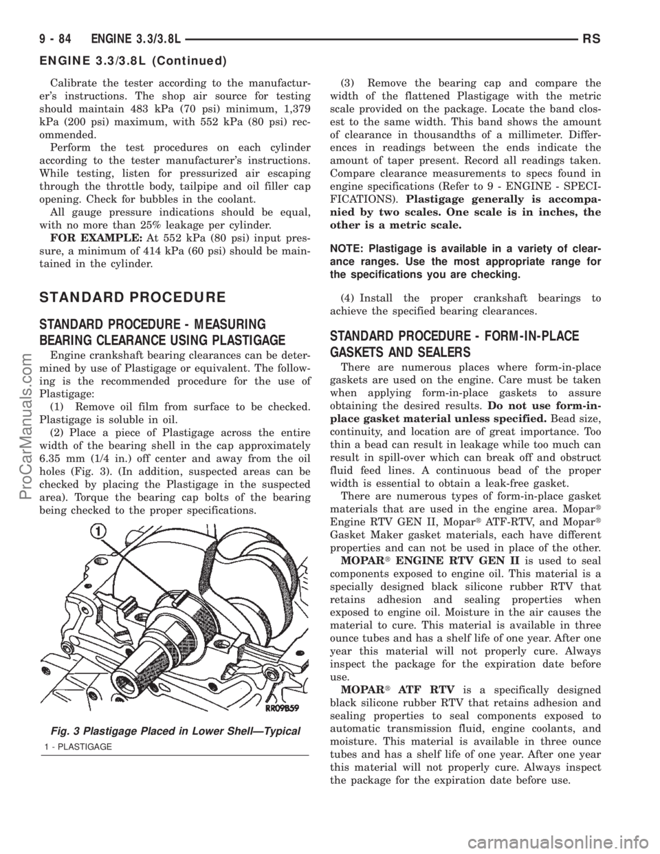
(2) Place a piece of Plastigage across the entire
width of the bearing shell in the cap approximately
6.35 mm (1/4 in.) off center and away from the oil
holes (Fig. 3). (In addition, suspected areas can be
checked by placing the Plastigage in the suspected
area). Torque the bearing cap bolts of the bearing
being checked to the proper specifications.(3) Remove the bearing cap and compare the
width of the flattened Plastigage with the metric
scale provided on the package. Locate the band clos-
est to the same width. This band shows the amount
of clearance in thousandths of a millimeter. Differ-
ences in readings between the ends indicate the
amount of taper present. Record all readings taken.
Compare clearance measurements to specs found in
engine specifications (Refer to 9 - ENGINE - SPECI-
FICATIONS).Plastigage generally is accompa-
nied by two scales. One scale is in inches, the
other is a metric scale.
NOTE: Plastigage is available in a variety of clear-
ance ranges. Use the most appropriate range for
the specifications you are checking.
(4) Install the proper crankshaft bearings to
achieve the specified bearing clearances.
STANDARD PROCEDURE - FORM-IN-PLACE
GASKETS AND SEALERS
There are numerous places where form-in-place
gaskets are used on the engine. Care must be taken
when applying form-in-place gaskets to assure
obtaining the desired results.Do not use form-in-
place gasket material unless specified.Bead size,
continuity, and location are of great importance. Too
thin a bead can result in leakage while too much can
result in spill-over which can break off and obstruct
fluid feed lines. A continuous bead of the proper
width is essential to obtain a leak-free gasket.
There are numerous types of form-in-place gasket
materials that are used in the engine area. Mopart
Engine RTV GEN II, MopartATF-RTV, and Mopart
Gasket Maker gasket materials, each have different
properties and can not be used in place of the other.
MOPARtENGINE RTV GEN IIis used to seal
components exposed to engine oil. This material is a
specially designed black silicone rubber RTV that
retains adhesion and sealing properties when
exposed to engine oil. Moisture in the air causes the
material to cure. This material is available in three
ounce tubes and has a shelf life of one year. After one
year this material will not properly cure. Always
inspect the package for the expiration date before
use.
MOPARtATF RTVis a specifically designed
black silicone rubber RTV that retains adhesion and
sealing properties to seal components exposed to
automatic transmission fluid, engine coolants, and
moisture. This material is available in three ounce
tubes and has a shelf life of one year. After one year
this material will not properly cure. Always inspect
the package for the expiration date before use.
Fig. 3 Plastigage Placed in Lower ShellÐTypical
1 - PLASTIGAGE
9 - 84 ENGINE 3.3/3.8LRS
ENGINE 3.3/3.8L (Continued)
ProCarManuals.com
Page 1290 of 2399

(48) Remove the water pump pulley attaching
bolts and position pulley between pump hub and
housing.
(49) Disconnect the oil pressure switch electrical
connector.
(50) Disconnect wiring harness support clip from
engine oil dipstick tube.
(51) Install Special Tools 6912 and 8444 Adapters
on the right side (rear) of engine block (Fig. 9).
(52) Lower the vehicle.
(53) Remove the power steering pump and set
aside.
(54) Raise vehicle enough to allow engine dolly
Special Tool 6135 and cradle Special Tool 6710 with
post Special Tool 6848 and adaptor Special Tool 6909
to be installed under vehicle (Fig. 12).
(55) Loosen cradle/post mounts to allow movement
for positioning posts into locating holes on the engine
(Fig. 10) and (Fig. 11). Slowly lower vehicle and posi-
tion cradle/post mounts until the engine is resting on
posts. Tighten all cradle/post mounts to cradle frame.
This will keep mounts from moving when removing
or installing engine and transmission.(56) Lower vehicle so the weight ofONLY THE
ENGINE AND TRANSMISSIONis on the cradle.
(57) Install and secure the safety straps to the cra-
dle fixture and around the engine (Fig. 12).
(58) Remove the engine right side mount to engine
attaching bolts (Fig. 13).
(59) Remove the left mount through bolt (Fig. 14).
(60) Raise vehicle slowly. It is necessary to move
the engine/transmission assembly with the dolly to
allow for removal around body flanges.
Fig. 9 ADAPTER TOOLS MOUNTED ON BLOCK
1 - SPECIAL TOOL 6912
2 - SPECIAL TOOL 8444
Fig. 10 Positioning Special Tool 6848 for use with
Adapters 8444 & 6912
1 - SLOTS
2 - SPECIAL TOOLS 6848
Fig. 11 Special Tools 6848 with Adapters 6909
1 - OIL FILTER
2 - SPECIAL TOOLS 6909
3 - OIL PAN
4 - SPECIAL TOOLS 6848
RSENGINE 3.3/3.8L9-89
ENGINE 3.3/3.8L (Continued)
ProCarManuals.com