2002 CHRYSLER CARAVAN timing belt
[x] Cancel search: timing beltPage 1418 of 2399
(3) Install accessory drive belt (Refer to 7 - COOL-
ING/ACCESSORY DRIVE/DRIVE BELTS - INSTAL-
LATION).
(4) Install power steering belt (Refer to 7 - COOL-
ING/ACCESSORY DRIVE/DRIVE BELTS - INSTAL-
LATION).
(5) Install right engine mount.
(6) Install air cleaner housing.
(7) Install engine cover (Refer to 9 - ENGINE -
INSTALLATION).
(8) Connect negative battery cable.
INSTALLATION - TIMING BELT INNER COVER
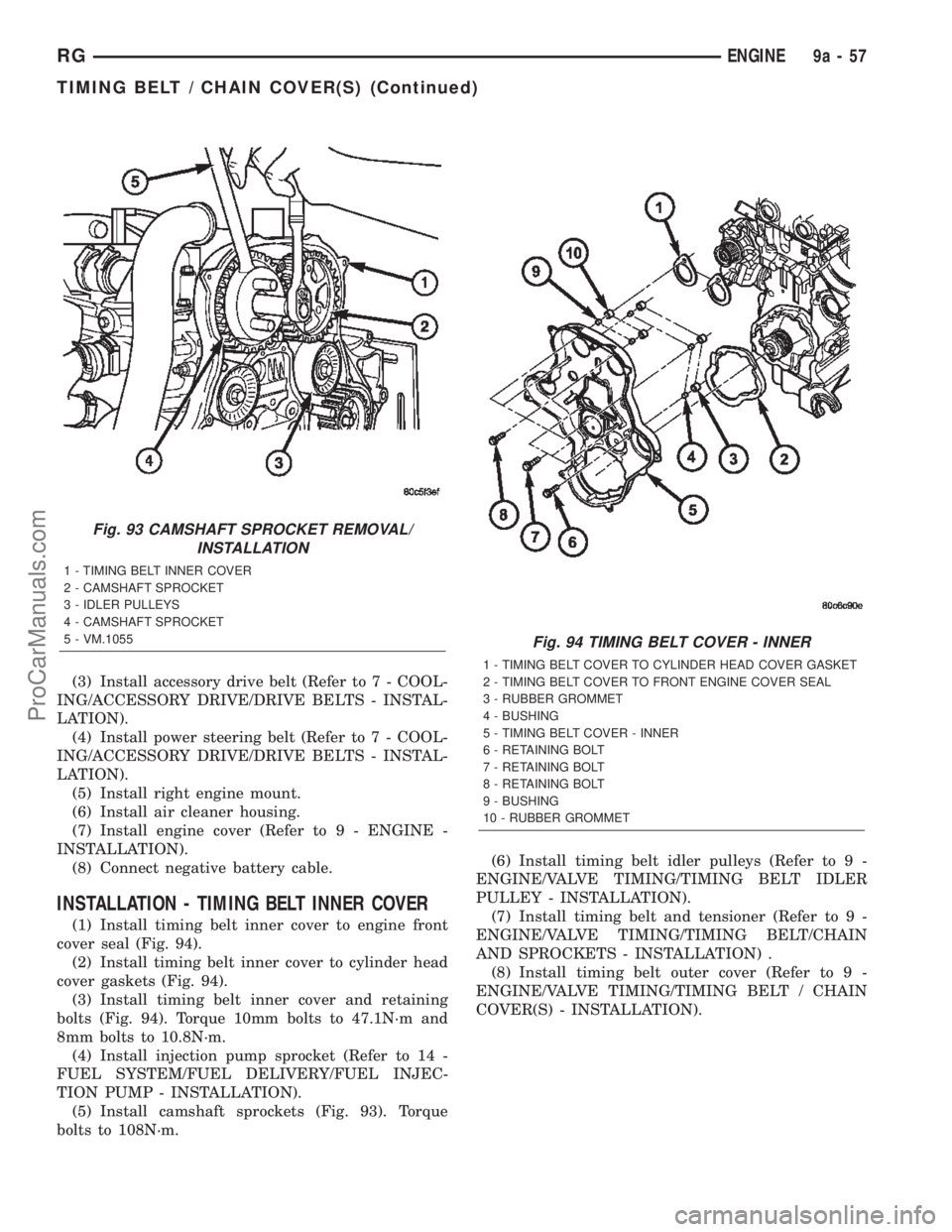
(1) Install timing belt inner cover to engine front
cover seal (Fig. 94).
(2) Install timing belt inner cover to cylinder head
cover gaskets (Fig. 94).
(3) Install timing belt inner cover and retaining
bolts (Fig. 94). Torque 10mm bolts to 47.1N´m and
8mm bolts to 10.8N´m.
(4) Install injection pump sprocket (Refer to 14 -
FUEL SYSTEM/FUEL DELIVERY/FUEL INJEC-
TION PUMP - INSTALLATION).
(5) Install camshaft sprockets (Fig. 93). Torque
bolts to 108N´m.(6) Install timing belt idler pulleys (Refer to 9 -
ENGINE/VALVE TIMING/TIMING BELT IDLER
PULLEY - INSTALLATION).
(7) Install timing belt and tensioner (Refer to 9 -
ENGINE/VALVE TIMING/TIMING BELT/CHAIN
AND SPROCKETS - INSTALLATION) .
(8) Install timing belt outer cover (Refer to 9 -
ENGINE/VALVE TIMING/TIMING BELT / CHAIN
COVER(S) - INSTALLATION).
Fig. 93 CAMSHAFT SPROCKET REMOVAL/
INSTALLATION
1 - TIMING BELT INNER COVER
2 - CAMSHAFT SPROCKET
3 - IDLER PULLEYS
4 - CAMSHAFT SPROCKET
5 - VM.1055
Fig. 94 TIMING BELT COVER - INNER
1 - TIMING BELT COVER TO CYLINDER HEAD COVER GASKET
2 - TIMING BELT COVER TO FRONT ENGINE COVER SEAL
3 - RUBBER GROMMET
4 - BUSHING
5 - TIMING BELT COVER - INNER
6 - RETAINING BOLT
7 - RETAINING BOLT
8 - RETAINING BOLT
9 - BUSHING
10 - RUBBER GROMMET
RGENGINE9a-57
TIMING BELT / CHAIN COVER(S) (Continued)
ProCarManuals.com
Page 1419 of 2399
(9) Install vibration damper (Refer to 9 - ENGINE/
ENGINE BLOCK/VIBRATION DAMPER - INSTAL-
LATION).
(10) Install accessory drive belt (Refer to 7 -
COOLING/ACCESSORY DRIVE/DRIVE BELTS -
INSTALLATION).
(11) Install power steering belt (Refer to 7 - COOL-
ING/ACCESSORY DRIVE/DRIVE BELTS - INSTAL-
LATION).
(12) Install right engine mount assembly.
(13) Install air cleaner housing.
(14) Install engine cover (Refer to 9 - ENGINE -
INSTALLATION).
(15) Connect negative battery cable.
TIMING BELT IDLER PULLEY
REMOVAL
(1) Disconnect negative battery cable.
(2) Remove engine cover (Refer to 9 - ENGINE -
REMOVAL).
(3) Remove air cleaner housing.
(4) Support engine and remove right engine
mount.
(5) Remove power steering belt (Refer to 7 -
COOLING/ACCESSORY DRIVE/DRIVE BELTS -
REMOVAL).
(6) Remove accessory drive belt (Refer to 7 -
COOLING/ACCESSORY DRIVE/DRIVE BELTS -
REMOVAL).
(7) Remove vibration damper (Refer to 9 -
ENGINE/ENGINE BLOCK/VIBRATION DAMPER -
REMOVAL).
(8) Remove timing belt outer cover (Refer to 9 -
ENGINE/VALVE TIMING/TIMING BELT / CHAIN
COVER(S) - REMOVAL).
(9) Remove timing belt (Refer to 9 - ENGINE/
VALVE TIMING/TIMING BELT/CHAIN AND
SPROCKETS - REMOVAL).
NOTE: Idler pulley retaining bolts are LHD thread.
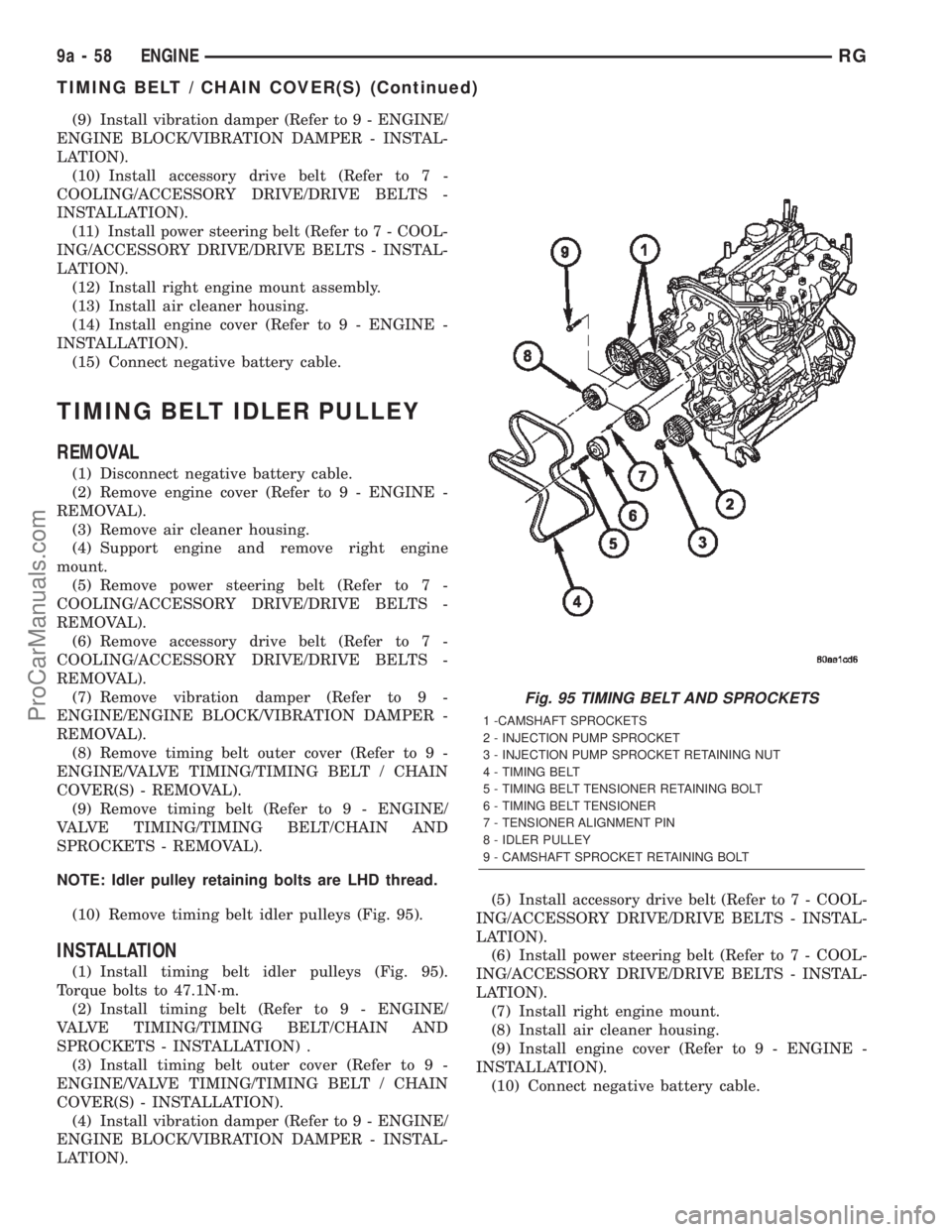
(10) Remove timing belt idler pulleys (Fig. 95).
INSTALLATION
(1) Install timing belt idler pulleys (Fig. 95).
Torque bolts to 47.1N´m.
(2) Install timing belt (Refer to 9 - ENGINE/
VALVE TIMING/TIMING BELT/CHAIN AND
SPROCKETS - INSTALLATION) .
(3) Install timing belt outer cover (Refer to 9 -
ENGINE/VALVE TIMING/TIMING BELT / CHAIN
COVER(S) - INSTALLATION).
(4) Install vibration damper (Refer to 9 - ENGINE/
ENGINE BLOCK/VIBRATION DAMPER - INSTAL-
LATION).(5) Install accessory drive belt (Refer to 7 - COOL-
ING/ACCESSORY DRIVE/DRIVE BELTS - INSTAL-
LATION).
(6) Install power steering belt (Refer to 7 - COOL-
ING/ACCESSORY DRIVE/DRIVE BELTS - INSTAL-
LATION).
(7) Install right engine mount.
(8) Install air cleaner housing.
(9) Install engine cover (Refer to 9 - ENGINE -
INSTALLATION).
(10) Connect negative battery cable.
Fig. 95 TIMING BELT AND SPROCKETS
1 -CAMSHAFT SPROCKETS
2 - INJECTION PUMP SPROCKET
3 - INJECTION PUMP SPROCKET RETAINING NUT
4 - TIMING BELT
5 - TIMING BELT TENSIONER RETAINING BOLT
6 - TIMING BELT TENSIONER
7 - TENSIONER ALIGNMENT PIN
8 - IDLER PULLEY
9 - CAMSHAFT SPROCKET RETAINING BOLT
9a - 58 ENGINERG
TIMING BELT / CHAIN COVER(S) (Continued)
ProCarManuals.com
Page 1420 of 2399
TMNG BELT/CHAIN
TENSIONER
REMOVAL
(1) Disconnect negative battery cable.
(2) Remove engine cover (Refer to 9 - ENGINE -
REMOVAL).
(3) Remove air cleaner housing.
(4) Support engine and remove right engine
mount.
(5) Remove power steering belt (Refer to 7 -
COOLING/ACCESSORY DRIVE/DRIVE BELTS -
REMOVAL).
(6) Remove accessory drive belt (Refer to 7 -
COOLING/ACCESSORY DRIVE/DRIVE BELTS -
REMOVAL).
(7) Remove vibration damper (Refer to 9 -
ENGINE/ENGINE BLOCK/VIBRATION DAMPER -
REMOVAL).
(8) Remove timing belt outer cover (Refer to 9 -
ENGINE/VALVE TIMING/TIMING BELT / CHAIN
COVER(S) - REMOVAL).
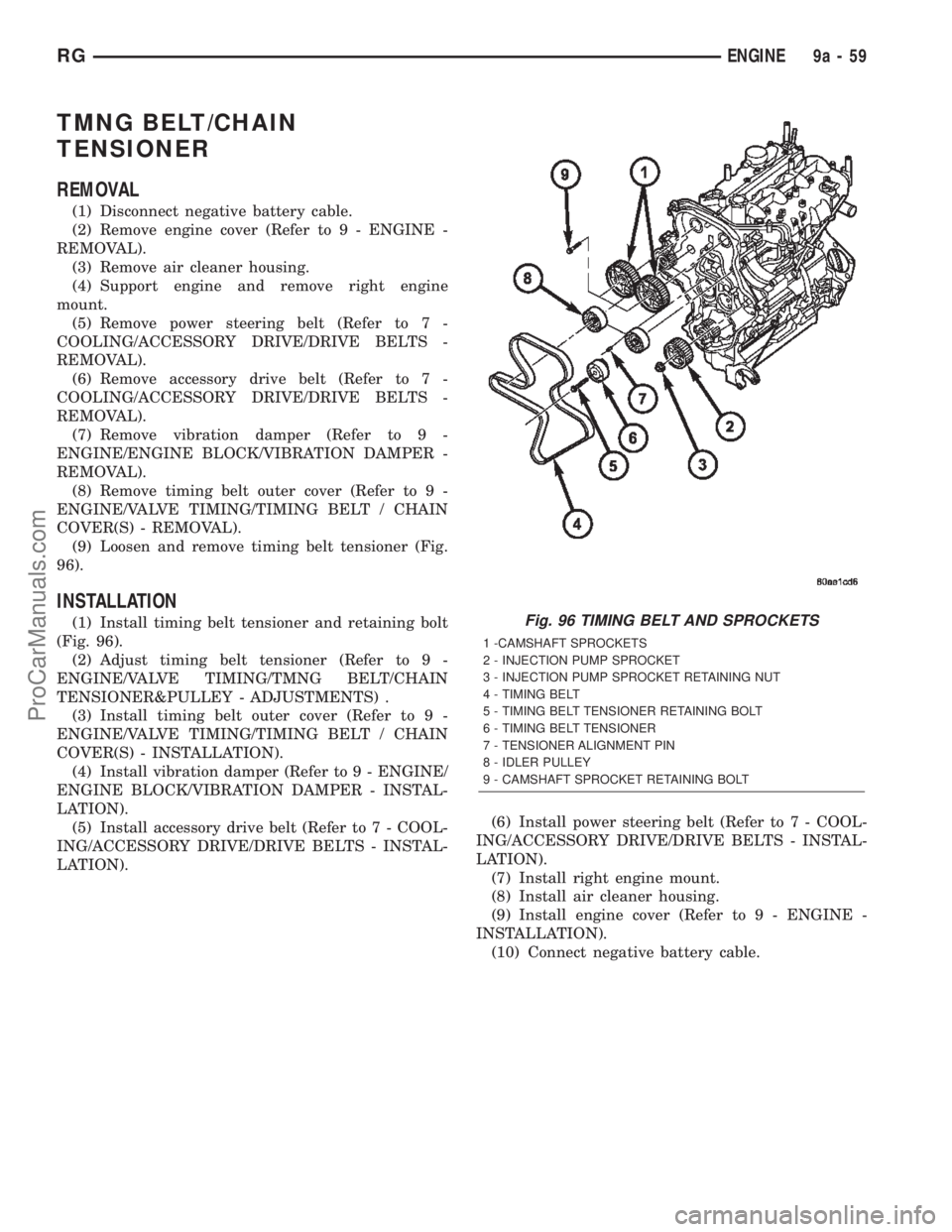
(9) Loosen and remove timing belt tensioner (Fig.
96).
INSTALLATION
(1) Install timing belt tensioner and retaining bolt
(Fig. 96).
(2) Adjust timing belt tensioner (Refer to 9 -
ENGINE/VALVE TIMING/TMNG BELT/CHAIN
TENSIONER&PULLEY - ADJUSTMENTS) .
(3) Install timing belt outer cover (Refer to 9 -
ENGINE/VALVE TIMING/TIMING BELT / CHAIN
COVER(S) - INSTALLATION).
(4) Install vibration damper (Refer to 9 - ENGINE/
ENGINE BLOCK/VIBRATION DAMPER - INSTAL-
LATION).
(5) Install accessory drive belt (Refer to 7 - COOL-
ING/ACCESSORY DRIVE/DRIVE BELTS - INSTAL-
LATION).(6) Install power steering belt (Refer to 7 - COOL-
ING/ACCESSORY DRIVE/DRIVE BELTS - INSTAL-
LATION).
(7) Install right engine mount.
(8) Install air cleaner housing.
(9) Install engine cover (Refer to 9 - ENGINE -
INSTALLATION).
(10) Connect negative battery cable.Fig. 96 TIMING BELT AND SPROCKETS
1 -CAMSHAFT SPROCKETS
2 - INJECTION PUMP SPROCKET
3 - INJECTION PUMP SPROCKET RETAINING NUT
4 - TIMING BELT
5 - TIMING BELT TENSIONER RETAINING BOLT
6 - TIMING BELT TENSIONER
7 - TENSIONER ALIGNMENT PIN
8 - IDLER PULLEY
9 - CAMSHAFT SPROCKET RETAINING BOLT
RGENGINE9a-59
ProCarManuals.com
Page 1421 of 2399
ADJUSTMENTS
ADJUSTMENT - TIMING BELT TENSIONER
(1) With timing belt outer cover removed and tim-
ing belt installed.
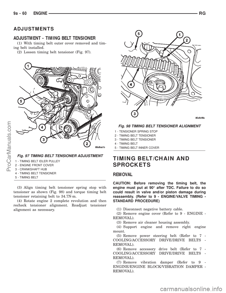
(2) Loosen timing belt tensioner (Fig. 97).
(3) Align timing belt tensioner spring stop with
tensioner as shown (Fig. 98) and torque timing belt
tensioner retaining bolt to 34.7N´m.
(4) Rotate engine 2 complete revolution and then
recheck tensioner alignment. Readjust tensioner
alignment as necessary.
TIMING BELT/CHAIN AND
SPROCKETS
REMOVAL
CAUTION: Before removing the timing belt, the
engine must put at 90É after TDC. Failure to do so
could result in valve and/or piston damage during
reassembly. (Refer to 9 - ENGINE/VALVE TIMING -
STANDARD PROCEDURE)
(1) Disconnect negative battery cable.
(2) Remove engine cover (Refer to 9 - ENGINE -
REMOVAL).
(3) Remove air cleaner housing assembly.
(4) Support engine and remove right engine
mount.
(5) Remove power steering belt (Refer to 7 -
COOLING/ACCESSORY DRIVE/DRIVE BELTS -
REMOVAL).
(6) Remove accessory drive belt (Refer to 7 -
COOLING/ACCESSORY DRIVE/DRIVE BELTS -
REMOVAL).
(7) Remove vibration damper (Refer to 9 -
ENGINE/ENGINE BLOCK/VIBRATION DAMPER -
REMOVAL).
Fig. 97 TIMING BELT TENSIONER ADJUSTMENT
1 - TIMING BELT IDLER PULLEY
2 - ENGINE FRONT COVER
3 - CRANKSHAFT HUB
4 - TIMING BELT TENSIONER
5 - TIMING BELT
Fig. 98 TIMING BELT TENSIONER ALIGNMENT
1 - TENSIONER SPRING STOP
2 - TIMING BELT TENSIONER
3 - TIMING BELT TENSIONER
4 - TIMING BELT
5 - TIMING BELT INNER COVER
9a - 60 ENGINERG
ProCarManuals.com
Page 1422 of 2399
(8) Remove timing belt outer cover (Refer to 9 -
ENGINE/VALVE TIMING/TIMING BELT / CHAIN
COVER(S) - REMOVAL).
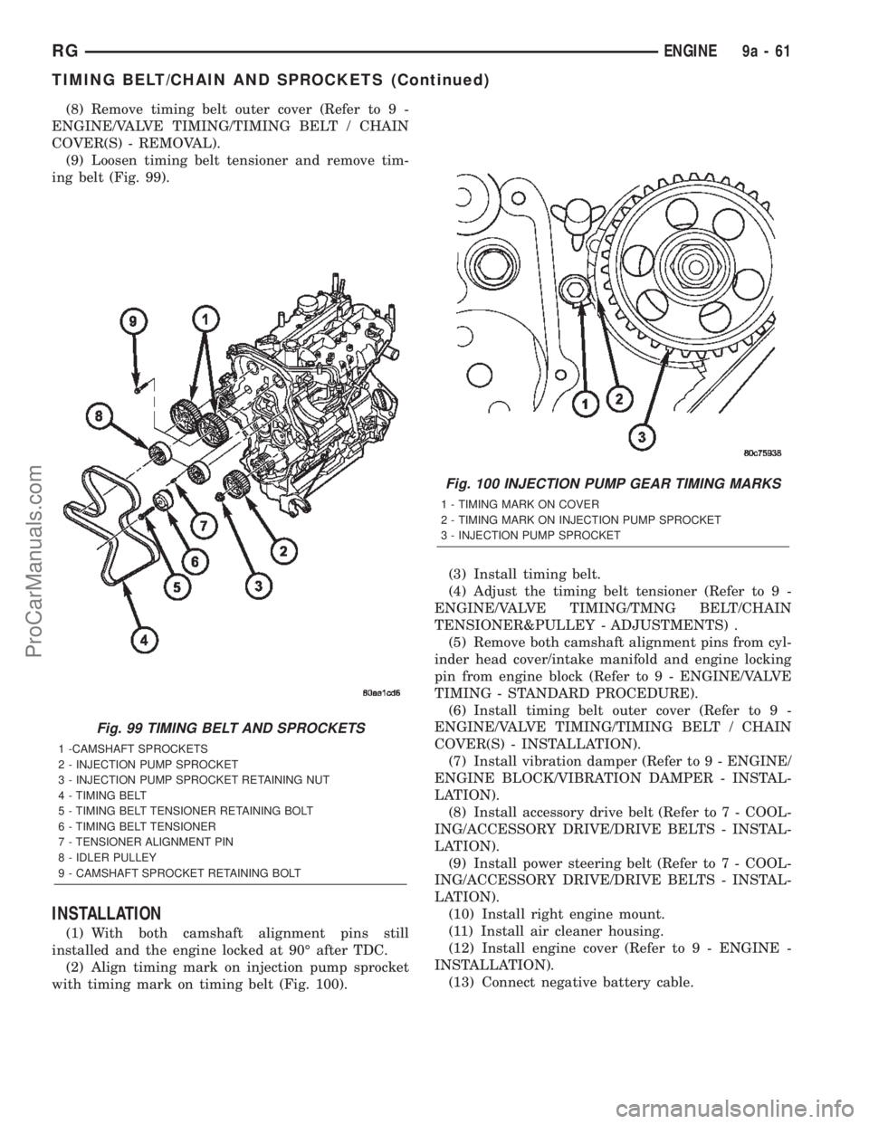
(9) Loosen timing belt tensioner and remove tim-
ing belt (Fig. 99).
INSTALLATION
(1) With both camshaft alignment pins still
installed and the engine locked at 90É after TDC.
(2) Align timing mark on injection pump sprocket
with timing mark on timing belt (Fig. 100).(3) Install timing belt.
(4) Adjust the timing belt tensioner (Refer to 9 -
ENGINE/VALVE TIMING/TMNG BELT/CHAIN
TENSIONER&PULLEY - ADJUSTMENTS) .
(5) Remove both camshaft alignment pins from cyl-
inder head cover/intake manifold and engine locking
pin from engine block (Refer to 9 - ENGINE/VALVE
TIMING - STANDARD PROCEDURE).
(6) Install timing belt outer cover (Refer to 9 -
ENGINE/VALVE TIMING/TIMING BELT / CHAIN
COVER(S) - INSTALLATION).
(7) Install vibration damper (Refer to 9 - ENGINE/
ENGINE BLOCK/VIBRATION DAMPER - INSTAL-
LATION).
(8) Install accessory drive belt (Refer to 7 - COOL-
ING/ACCESSORY DRIVE/DRIVE BELTS - INSTAL-
LATION).
(9) Install power steering belt (Refer to 7 - COOL-
ING/ACCESSORY DRIVE/DRIVE BELTS - INSTAL-
LATION).
(10) Install right engine mount.
(11) Install air cleaner housing.
(12) Install engine cover (Refer to 9 - ENGINE -
INSTALLATION).
(13) Connect negative battery cable.
Fig. 99 TIMING BELT AND SPROCKETS
1 -CAMSHAFT SPROCKETS
2 - INJECTION PUMP SPROCKET
3 - INJECTION PUMP SPROCKET RETAINING NUT
4 - TIMING BELT
5 - TIMING BELT TENSIONER RETAINING BOLT
6 - TIMING BELT TENSIONER
7 - TENSIONER ALIGNMENT PIN
8 - IDLER PULLEY
9 - CAMSHAFT SPROCKET RETAINING BOLT
Fig. 100 INJECTION PUMP GEAR TIMING MARKS
1 - TIMING MARK ON COVER
2 - TIMING MARK ON INJECTION PUMP SPROCKET
3 - INJECTION PUMP SPROCKET
RGENGINE9a-61
TIMING BELT/CHAIN AND SPROCKETS (Continued)
ProCarManuals.com
Page 1495 of 2399
(6) Support engine and remove right engine mount
assembly.
(7) Remove outer timing belt cover (Refer to 9 -
ENGINE/VALVE TIMING/TIMING BELT / CHAIN
COVER(S) - REMOVAL).
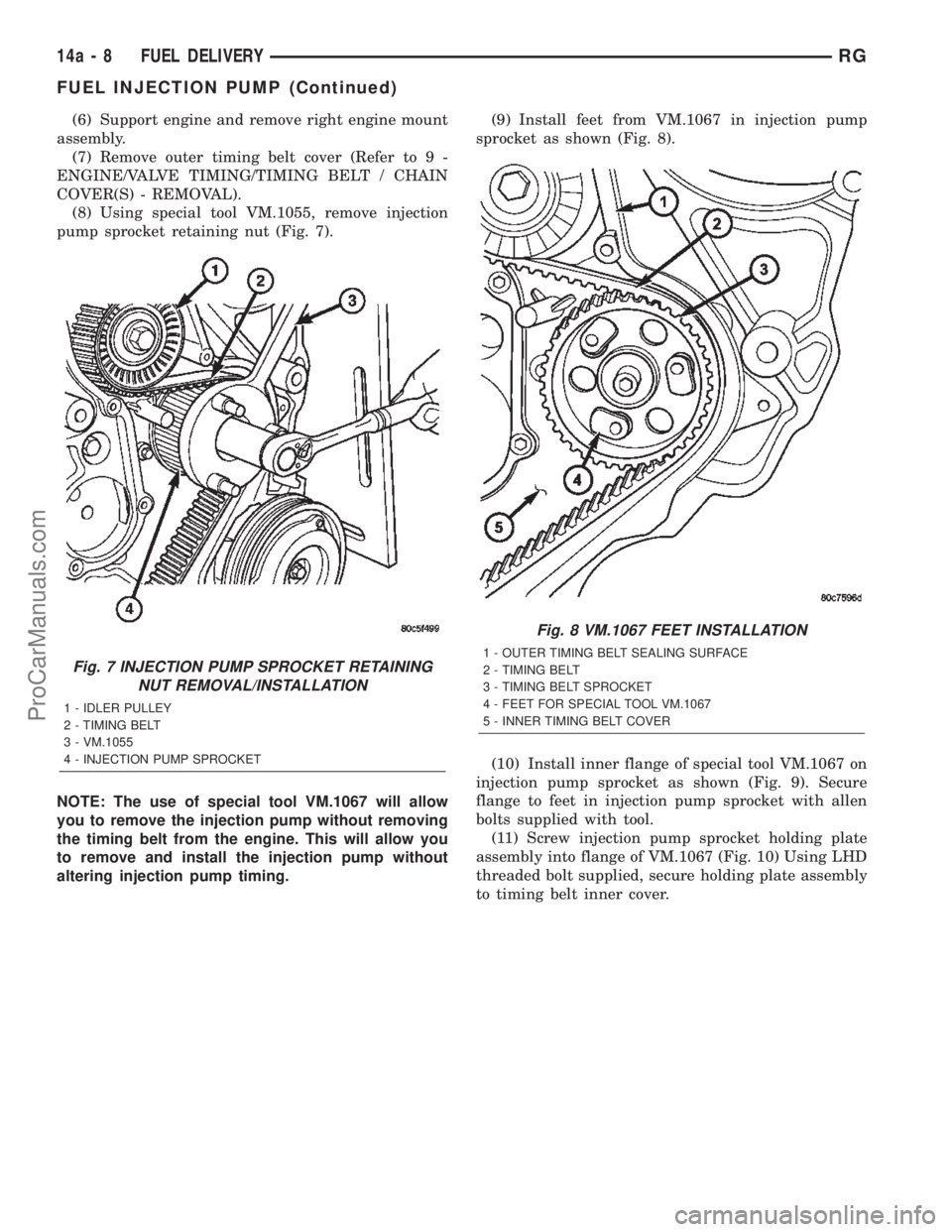
(8) Using special tool VM.1055, remove injection
pump sprocket retaining nut (Fig. 7).
NOTE: The use of special tool VM.1067 will allow
you to remove the injection pump without removing
the timing belt from the engine. This will allow you
to remove and install the injection pump without
altering injection pump timing.(9) Install feet from VM.1067 in injection pump
sprocket as shown (Fig. 8).
(10) Install inner flange of special tool VM.1067 on
injection pump sprocket as shown (Fig. 9). Secure
flange to feet in injection pump sprocket with allen
bolts supplied with tool.
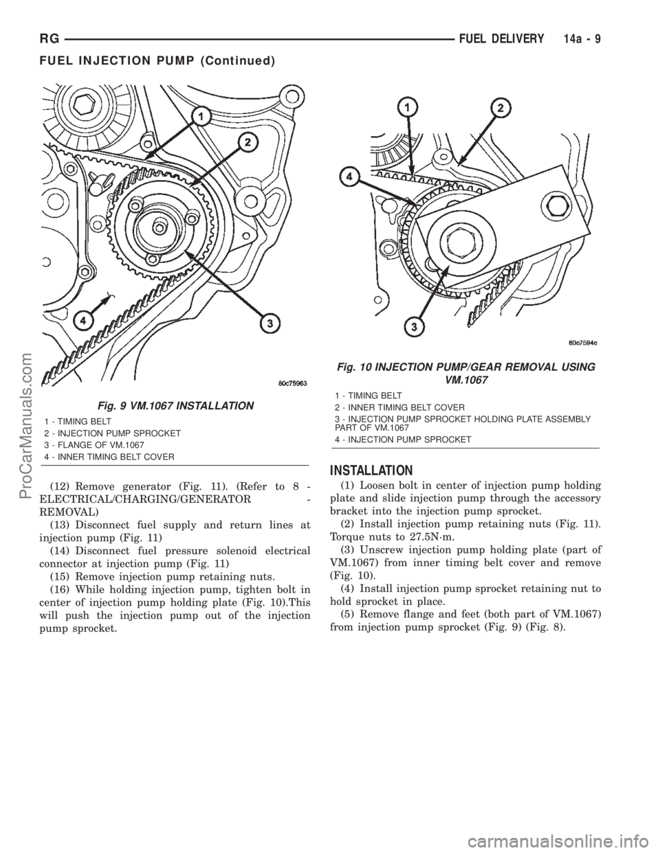
(11) Screw injection pump sprocket holding plate
assembly into flange of VM.1067 (Fig. 10) Using LHD
threaded bolt supplied, secure holding plate assembly
to timing belt inner cover.
Fig. 7 INJECTION PUMP SPROCKET RETAINING
NUT REMOVAL/INSTALLATION
1 - IDLER PULLEY
2 - TIMING BELT
3 - VM.1055
4 - INJECTION PUMP SPROCKET
Fig. 8 VM.1067 FEET INSTALLATION
1 - OUTER TIMING BELT SEALING SURFACE
2 - TIMING BELT
3 - TIMING BELT SPROCKET
4 - FEET FOR SPECIAL TOOL VM.1067
5 - INNER TIMING BELT COVER
14a - 8 FUEL DELIVERYRG
FUEL INJECTION PUMP (Continued)
ProCarManuals.com
Page 1496 of 2399
(12) Remove generator (Fig. 11). (Refer to 8 -
ELECTRICAL/CHARGING/GENERATOR -
REMOVAL)
(13) Disconnect fuel supply and return lines at
injection pump (Fig. 11)
(14) Disconnect fuel pressure solenoid electrical
connector at injection pump (Fig. 11)
(15) Remove injection pump retaining nuts.
(16) While holding injection pump, tighten bolt in
center of injection pump holding plate (Fig. 10).This
will push the injection pump out of the injection
pump sprocket.
INSTALLATION
(1) Loosen bolt in center of injection pump holding
plate and slide injection pump through the accessory
bracket into the injection pump sprocket.
(2) Install injection pump retaining nuts (Fig. 11).
Torque nuts to 27.5N´m.
(3) Unscrew injection pump holding plate (part of
VM.1067) from inner timing belt cover and remove
(Fig. 10).
(4) Install injection pump sprocket retaining nut to
hold sprocket in place.
(5) Remove flange and feet (both part of VM.1067)
from injection pump sprocket (Fig. 9) (Fig. 8).
Fig. 9 VM.1067 INSTALLATION
1 - TIMING BELT
2 - INJECTION PUMP SPROCKET
3 - FLANGE OF VM.1067
4 - INNER TIMING BELT COVER
Fig. 10 INJECTION PUMP/GEAR REMOVAL USING
VM.1067
1 - TIMING BELT
2 - INNER TIMING BELT COVER
3 - INJECTION PUMP SPROCKET HOLDING PLATE ASSEMBLY
PART OF VM.1067
4 - INJECTION PUMP SPROCKET
RGFUEL DELIVERY14a-9
FUEL INJECTION PUMP (Continued)
ProCarManuals.com
Page 1497 of 2399
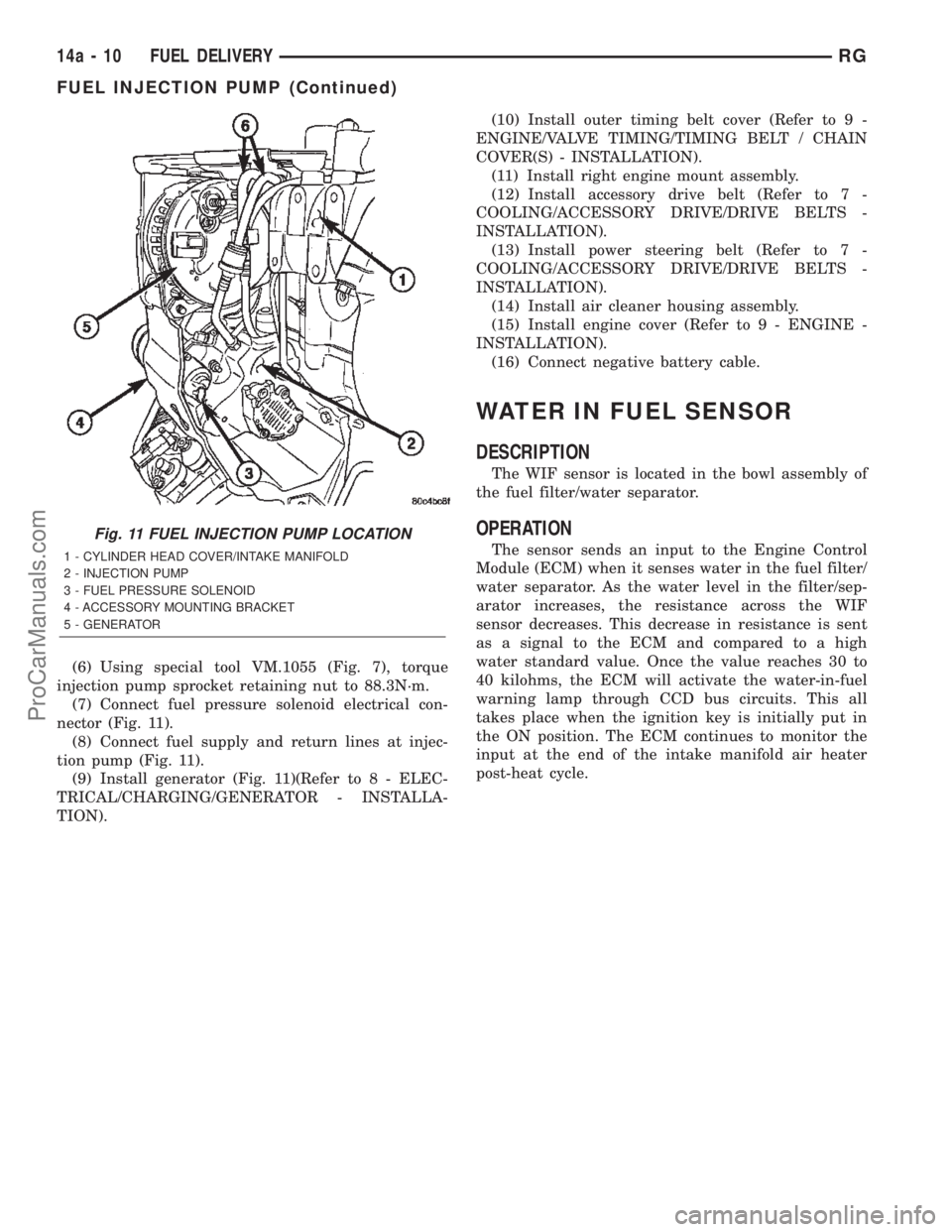
(6) Using special tool VM.1055 (Fig. 7), torque
injection pump sprocket retaining nut to 88.3N´m.
(7) Connect fuel pressure solenoid electrical con-
nector (Fig. 11).
(8) Connect fuel supply and return lines at injec-
tion pump (Fig. 11).
(9) Install generator (Fig. 11)(Refer to 8 - ELEC-
TRICAL/CHARGING/GENERATOR - INSTALLA-
TION).(10) Install outer timing belt cover (Refer to 9 -
ENGINE/VALVE TIMING/TIMING BELT / CHAIN
COVER(S) - INSTALLATION).
(11) Install right engine mount assembly.
(12) Install accessory drive belt (Refer to 7 -
COOLING/ACCESSORY DRIVE/DRIVE BELTS -
INSTALLATION).
(13) Install power steering belt (Refer to 7 -
COOLING/ACCESSORY DRIVE/DRIVE BELTS -
INSTALLATION).
(14) Install air cleaner housing assembly.
(15) Install engine cover (Refer to 9 - ENGINE -
INSTALLATION).
(16) Connect negative battery cable.
WATER IN FUEL SENSOR
DESCRIPTION
The WIF sensor is located in the bowl assembly of
the fuel filter/water separator.
OPERATION
The sensor sends an input to the Engine Control
Module (ECM) when it senses water in the fuel filter/
water separator. As the water level in the filter/sep-
arator increases, the resistance across the WIF
sensor decreases. This decrease in resistance is sent
as a signal to the ECM and compared to a high
water standard value. Once the value reaches 30 to
40 kilohms, the ECM will activate the water-in-fuel
warning lamp through CCD bus circuits. This all
takes place when the ignition key is initially put in
the ON position. The ECM continues to monitor the
input at the end of the intake manifold air heater
post-heat cycle.
Fig. 11 FUEL INJECTION PUMP LOCATION
1 - CYLINDER HEAD COVER/INTAKE MANIFOLD
2 - INJECTION PUMP
3 - FUEL PRESSURE SOLENOID
4 - ACCESSORY MOUNTING BRACKET
5 - GENERATOR
14a - 10 FUEL DELIVERYRG
FUEL INJECTION PUMP (Continued)
ProCarManuals.com