2002 CHRYSLER CARAVAN oil filter
[x] Cancel search: oil filterPage 1718 of 2399
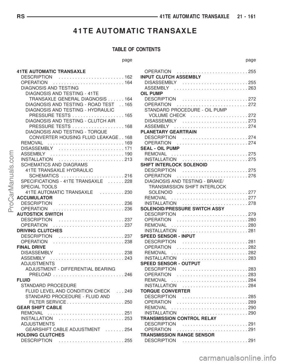
41TE AUTOMATIC TRANSAXLE
TABLE OF CONTENTS
page page
41TE AUTOMATIC TRANSAXLE
DESCRIPTION........................162
OPERATION..........................164
DIAGNOSIS AND TESTING
DIAGNOSIS AND TESTING - 41TE
TRANSAXLE GENERAL DIAGNOSIS......164
DIAGNOSIS AND TESTING - ROAD TEST . . 165
DIAGNOSIS AND TESTING - HYDRAULIC
PRESSURE TESTS...................165
DIAGNOSIS AND TESTING - CLUTCH AIR
PRESSURE TESTS...................168
DIAGNOSIS AND TESTING - TORQUE
CONVERTER HOUSING FLUID LEAKAGE . . 168
REMOVAL............................169
DISASSEMBLY........................171
ASSEMBLY...........................190
INSTALLATION........................213
SCHEMATICS AND DIAGRAMS
41TE TRANSAXLE HYDRAULIC
SCHEMATICS.......................216
SPECIFICATIONS - 41TE TRANSAXLE......228
SPECIAL TOOLS
41TE AUTOMATIC TRANSAXLE.........230
ACCUMULATOR
DESCRIPTION........................236
OPERATION..........................236
AUTOSTICK SWITCH
DESCRIPTION........................237
OPERATION..........................237
DRIVING CLUTCHES
DESCRIPTION........................237
OPERATION..........................238
FINAL DRIVE
DISASSEMBLY........................238
ASSEMBLY...........................243
ADJUSTMENTS
ADJUSTMENT - DIFFERENTIAL BEARING
PRELOAD..........................246
FLUID
STANDARD PROCEDURE
FLUID LEVEL AND CONDITION CHECK . . . 249
STANDARD PROCEDURE - FLUID AND
FILTER SERVICE.....................250
GEAR SHIFT CABLE
REMOVAL............................251
INSTALLATION........................253
ADJUSTMENTS
GEARSHIFT CABLE ADJUSTMENT.......254
HOLDING CLUTCHES
DESCRIPTION........................255OPERATION..........................255
INPUT CLUTCH ASSEMBLY
DISASSEMBLY........................255
ASSEMBLY...........................263
OIL PUMP
DESCRIPTION........................272
OPERATION..........................272
STANDARD PROCEDURE - OIL PUMP
VOLUME CHECK.....................272
DISASSEMBLY........................273
ASSEMBLY...........................274
PLANETARY GEARTRAIN
DESCRIPTION........................274
OPERATION..........................274
SEAL - OIL PUMP
REMOVAL............................275
INSTALLATION........................275
SHIFT INTERLOCK SOLENOID
DESCRIPTION........................275
OPERATION..........................276
DIAGNOSIS AND TESTING - BRAKE/
TRANSMISSION SHIFT INTERLOCK
SOLENOID..........................277
REMOVAL............................277
INSTALLATION........................278
SOLENOID/PRESSURE SWITCH ASSY
DESCRIPTION........................279
OPERATION..........................280
REMOVAL............................280
INSTALLATION........................281
SPEED SENSOR - INPUT
DESCRIPTION........................281
OPERATION..........................282
REMOVAL............................282
INSTALLATION........................283
SPEED SENSOR - OUTPUT
DESCRIPTION........................283
OPERATION..........................283
REMOVAL............................284
INSTALLATION........................284
TORQUE CONVERTER
DESCRIPTION........................285
OPERATION..........................289
REMOVAL............................290
INSTALLATION........................290
TRANSMISSION CONTROL RELAY
DESCRIPTION........................291
OPERATION..........................291
TRANSMISSION RANGE SENSOR
DESCRIPTION........................291
RS41TE AUTOMATIC TRANSAXLE21 - 161
ProCarManuals.com
Page 1729 of 2399
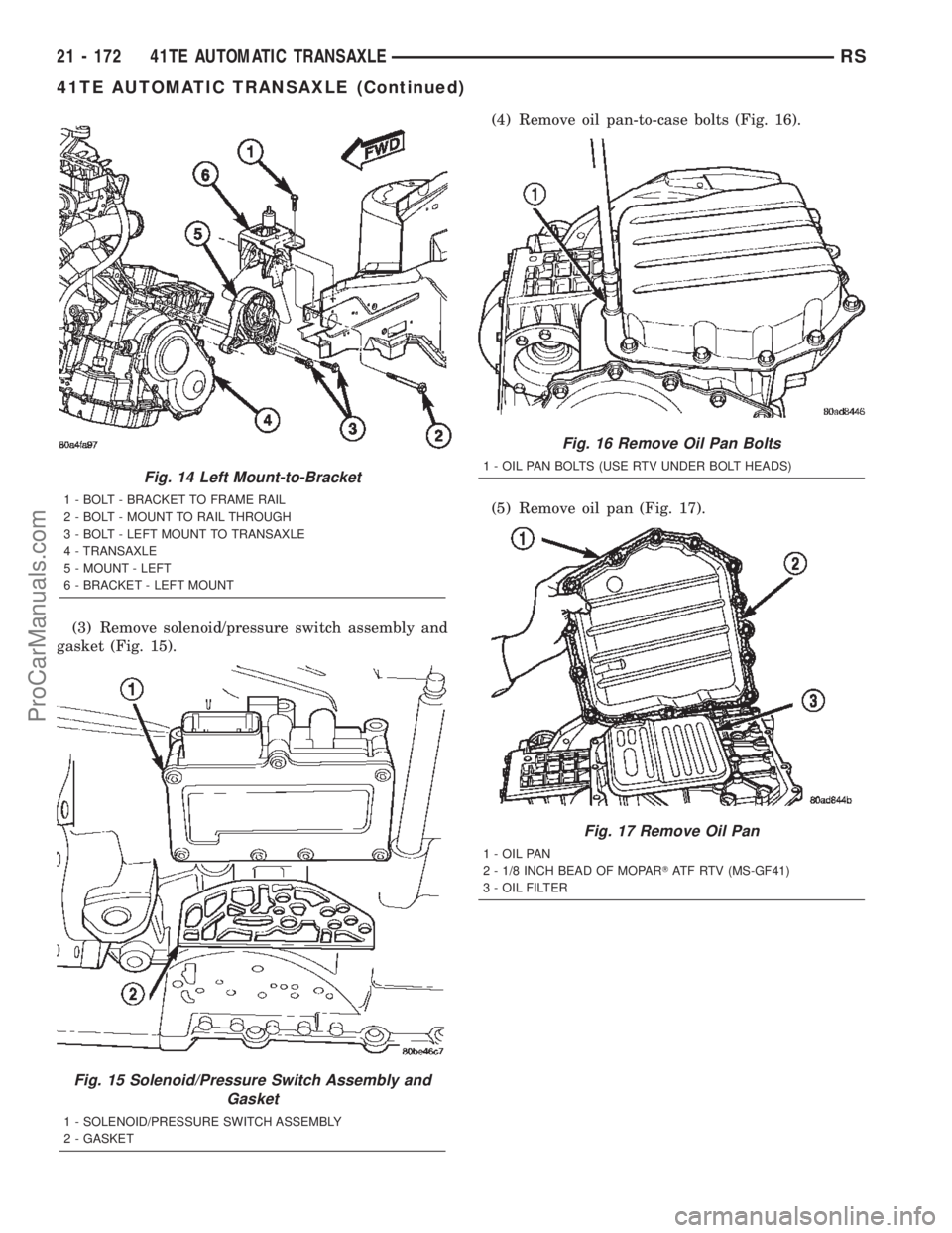
(3) Remove solenoid/pressure switch assembly and
gasket (Fig. 15).(4) Remove oil pan-to-case bolts (Fig. 16).
(5) Remove oil pan (Fig. 17).
Fig. 14 Left Mount-to-Bracket
1 - BOLT - BRACKET TO FRAME RAIL
2 - BOLT - MOUNT TO RAIL THROUGH
3 - BOLT - LEFT MOUNT TO TRANSAXLE
4 - TRANSAXLE
5 - MOUNT - LEFT
6 - BRACKET - LEFT MOUNT
Fig. 15 Solenoid/Pressure Switch Assembly and
Gasket
1 - SOLENOID/PRESSURE SWITCH ASSEMBLY
2 - GASKET
Fig. 16 Remove Oil Pan Bolts
1 - OIL PAN BOLTS (USE RTV UNDER BOLT HEADS)
Fig. 17 Remove Oil Pan
1 - OIL PAN
2 - 1/8 INCH BEAD OF MOPARTATF RTV (MS-GF41)
3 - OIL FILTER
21 - 172 41TE AUTOMATIC TRANSAXLERS
41TE AUTOMATIC TRANSAXLE (Continued)
ProCarManuals.com
Page 1730 of 2399
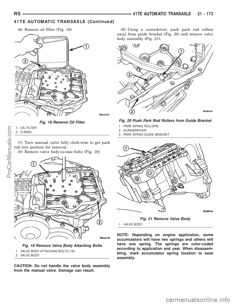
(6) Remove oil filter (Fig. 18).
(7) Turn manual valve fully clock-wise to get park
rod into position for removal.
(8) Remove valve body-to-case bolts (Fig. 19).
CAUTION: Do not handle the valve body assembly
from the manual valve. Damage can result.(9) Using a screwdriver, push park rod rollers
away from guide bracket (Fig. 20) and remove valve
body assembly (Fig. 21).
NOTE: Depending on engine application, some
accumulators will have two springs and others will
have one spring. The springs are color-coded
according to application and year. When disassem-
bling, mark accumulator spring location to ease
assembly.
Fig. 18 Remove Oil Filter
1 - OIL FILTER
2 - O-RING
Fig. 19 Remove Valve Body Attaching Bolts
1 - VALVE BODY ATTACHING BOLTS (18)
2 - VALVE BODY
Fig. 20 Push Park Rod Rollers from Guide Bracket
1 - PARK SPRAG ROLLERS
2 - SCREWDRIVER
3 - PARK SPRAG GUIDE BRACKET
Fig. 21 Remove Valve Body
1 - VALVE BODY
RS41TE AUTOMATIC TRANSAXLE21 - 173
41TE AUTOMATIC TRANSAXLE (Continued)
ProCarManuals.com
Page 1769 of 2399

(64) Install and torque valve body-to-case bolts to
12 N´m (105 in. lbs.) (Fig. 159).
(65) Install oil filter and new o-ring (Fig. 160).(66) Apply an 1/8º bead of MopartATF RTV (MS-
GF41) to oil pan and immediately install to case (Fig.
161).
(67) Install oil pan-to-case bolts and torque to 19
N´m (165 in. lbs.).
(68) Install solenoid/pressure switch assembly and
gasket to case (Fig. 162).
Fig. 159 Install Valve Body-to-Case Bolts
1 - VALVE BODY ATTACHING BOLTS (18)
2 - VALVE BODY
Fig. 160 Install Oil Filter
1 - OIL FILTER
2 - O-RING
Fig. 161 Install Oil Pan
1 - OIL PAN
2 - 1/8 INCH BEAD OF MOPARTATF RTV (MS-GF41)
3 - OIL FILTER
Fig. 162 Solenoid/Pressure Switch Assembly and
Gasket
1 - SOLENOID/PRESSURE SWITCH ASSEMBLY
2 - GASKET
21 - 212 41TE AUTOMATIC TRANSAXLERS
41TE AUTOMATIC TRANSAXLE (Continued)
ProCarManuals.com
Page 1807 of 2399
(6) Adjust transmission fluid level shown on the
indicator according to the chart.
(7) Check transmission for leaks.
Low fluid level can cause a variety of conditions
because it allows the pump to take in air along with
the fluid. As in any hydraulic system, air bubbles
make the fluid spongy, therefore, pressures will be
low and build up slowly.
Improper filling can also raise the fluid level too
high. When the transaxle has too much fluid, the
gears churn up foam and cause the same conditions
which occur with a low fluid level.
In either case, air bubbles can cause overheating
and/or fluid oxidation, and varnishing. This can
interfere with normal valve, clutch, and accumulator
operation. Foaming can also result in fluid escaping
from the transaxle vent where it may be mistaken
for a leak.
FLUID CONDITION
Along with fluid level, it is important to check the
condition of the fluid. When the fluid smells burned,
and is contaminated with metal or friction material
particles, a complete transaxle recondition is proba-
bly required. Be sure to examine the fluid on the dip-
stick closely. If there is any doubt about its condition,
drain out a sample for a double check.
MopartATF+4 (Automatic Transmission Fluid-
Type 9602) when new is red in color. The ATF is dyed
red so it can be identified from other fluids used in
the vehicle such as engine oil or antifreeze. The red
color is not permanent and is not an indicator of fluid
condition. As the vehicle is driven, the ATF will begin
to look darker in color and may eventually become
brown.This is normal.ATF+4 also has a unique
odor that may change with age. Consequently,odor
and color cannot be used to indicate the fluid
condition or the need for a fluid change.
After the fluid has been checked, seat the dipstick
fully to seal out water and dirt.
STANDARD PROCEDURE - FLUID AND FILTER
SERVICE
NOTE: Refer to the maintenance schedules in
LUBRICATION and MAINTENANCE, or the vehicle
owner's manual, for the recommended maintenance
(fluid/filter change) intervals for this transaxle.
NOTE: Only fluids of the type labeled MoparTATF+4
(Automatic Transmission Fluid) Type 9602 should
be used. A filter change should be made at the time
of the transmission oil change. The magnet (on the
inside of the oil pan) should also be cleaned with a
clean, dry cloth.NOTE: If the transaxle is disassembled for any rea-
son, the fluid and filter should be changed.
FLUID/FILTER SERVICE (RECOMMENDED)
(1) Raise vehicle on a hoist. Refer to LUBRICA-
TION and MAINTENANCE for proper procedures.
Place a drain container with a large opening, under
transaxle oil pan.
(2) Loosen pan bolts and tap the pan at one corner
to break it loose allowing fluid to drain, then remove
the oil pan.
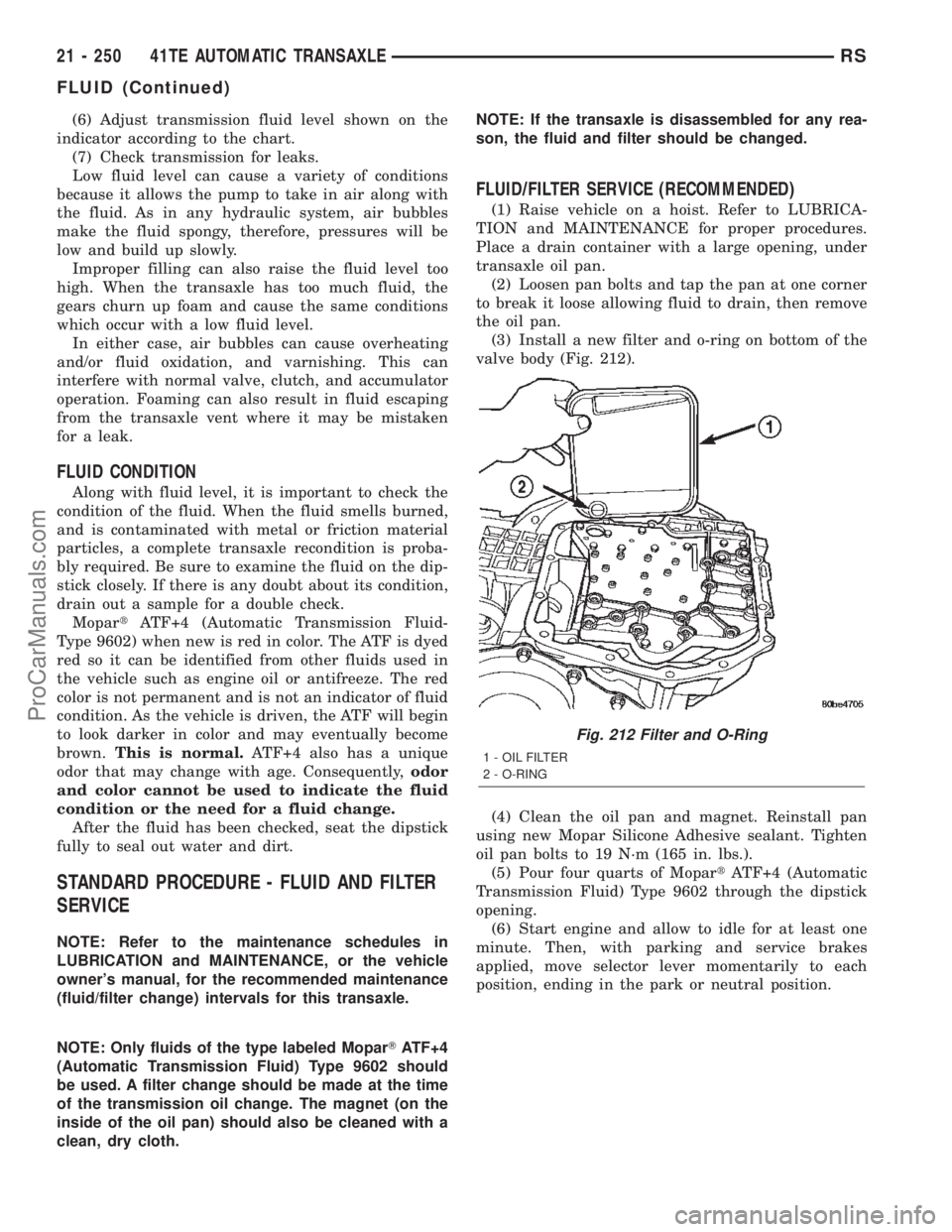
(3) Install a new filter and o-ring on bottom of the
valve body (Fig. 212).
(4) Clean the oil pan and magnet. Reinstall pan
using new Mopar Silicone Adhesive sealant. Tighten
oil pan bolts to 19 N´m (165 in. lbs.).
(5) Pour four quarts of MopartATF+4 (Automatic
Transmission Fluid) Type 9602 through the dipstick
opening.
(6) Start engine and allow to idle for at least one
minute. Then, with parking and service brakes
applied, move selector lever momentarily to each
position, ending in the park or neutral position.
Fig. 212 Filter and O-Ring
1 - OIL FILTER
2 - O-RING
21 - 250 41TE AUTOMATIC TRANSAXLERS
FLUID (Continued)
ProCarManuals.com
Page 1851 of 2399
SOLENOID SWITCH VALVE
The solenoid switch valve controls line pressure
from the LR/CC solenoid. In one position, it allows
the low/reverse clutch to be pressurized. In the other,
it directs line pressure to the converter control and
converter clutch valves.
MANUAL VALVE
The manual valve is operated by the mechanical
shift linkage. Its primary responsibility is to send
line pressure to the appropriate hydraulic circuits
and solenoids. The valve has three operating ranges
or positions.
CONVERTER CLUTCH SWITCH VALVE
The main responsibility of the converter clutch switch
valve is to control hydraulic pressure applied to the front
(off) side of the converter clutch piston. Line pressure
from the regulator valve is fed to the torque converter
regulator valve, where it passes through the valve, and is
slightly regulated. The pressure is then directed to the
converter clutch switch valve and to the front side of the
converter clutch piston. This pressure pushes the piston
back and disengages the converter clutch.
CONVERTER CLUTCH CONTROL VALVE
The converter clutch control valve controls the
back (on) side of the torque converter clutch. When
the TCM energizes or modulates the LR/CC solenoid
to apply the converter clutch piston, both the con-
verter clutch control valve and the converter control
valve move, allowing pressure to be applied to the
back side of the clutch.
T/C REGULATOR VALVE
The torque converter regulator valve slightly regu-
lates the flow of fluid to the torque converter.
LOW/REVERSE SWITCH VALVE
The low/reverse clutch is applied from different
sources, depending on whether low (1st) gear or
reverse is selected. The low/reverse switch valve
alternates positions depending on from which direc-
tion fluid pressure is applied. By design, when the
valve is shifted by fluid pressure from one channel,
the opposing channel is blocked. The switch valve
alienates the possibility of a sticking ball check, thus
providing consistent application of the low/reverse
clutch under all operating conditions.
REMOVAL
REMOVAL
NOTE: If valve body is replaced or reconditioned,
the TCM Quick Learn Procedure must be per-formed. (Refer to 8 - ELECTRICAL/ELECTRONIC
CONTROL MODULES/TRANSMISSION CONTROL
MODULE - STANDARD PROCEDURE)
(1) Disconnect battery negative cable.
(2) Disconnect gearshift cable from manual valve
lever.
(3) Remove manual valve lever from manual shaft.
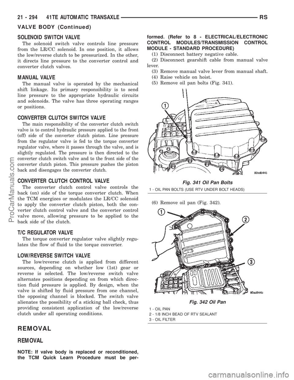
(4) Raise vehicle on hoist.
(5) Remove oil pan bolts (Fig. 341).
(6) Remove oil pan (Fig. 342).
Fig. 341 Oil Pan Bolts
1 - OIL PAN BOLTS (USE RTV UNDER BOLT HEADS)
Fig. 342 Oil Pan
1 - OIL PAN
2 - 1/8 INCH BEAD OF RTV SEALANT
3 - OIL FILTER
21 - 294 41TE AUTOMATIC TRANSAXLERS
VALVE BODY (Continued)
ProCarManuals.com
Page 1852 of 2399
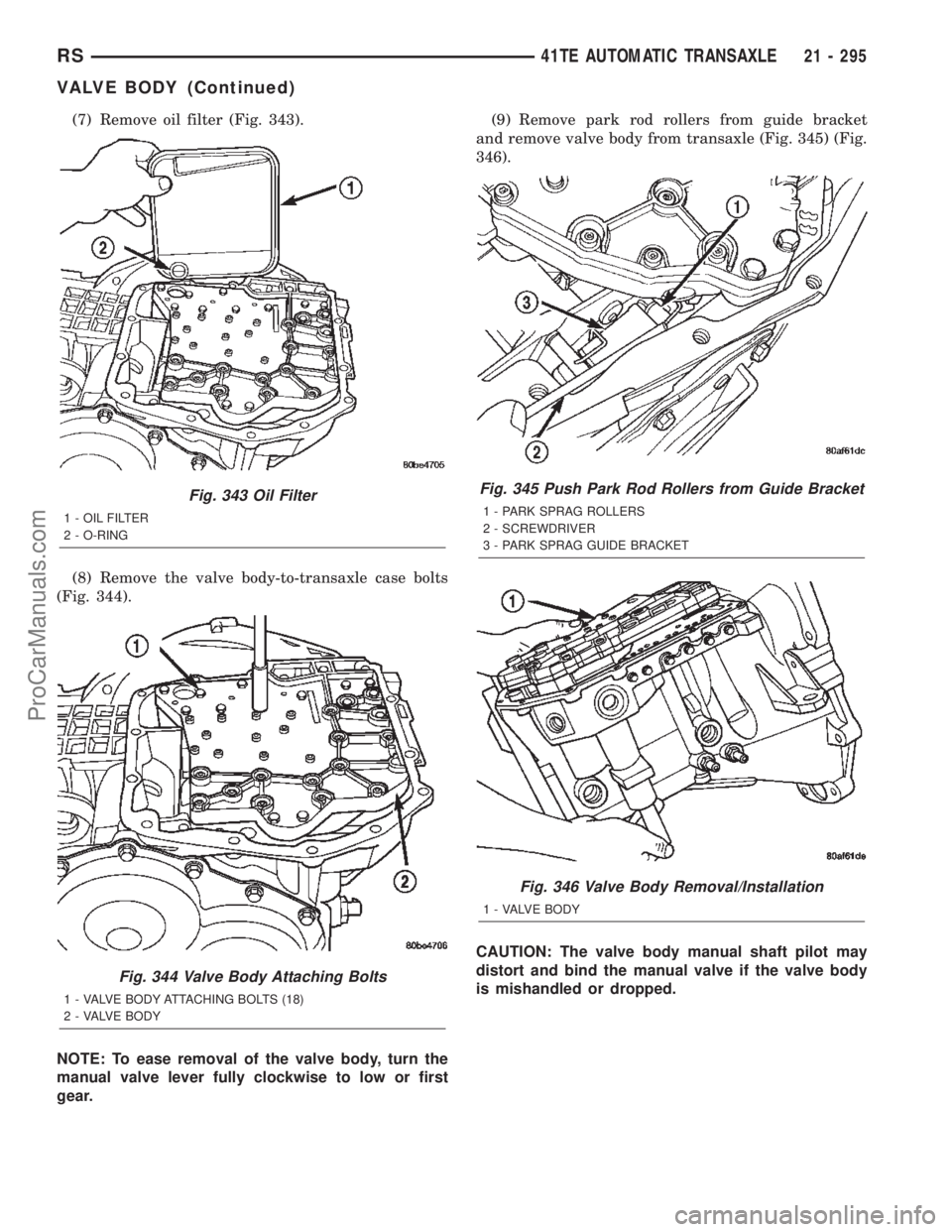
(7) Remove oil filter (Fig. 343).
(8) Remove the valve body-to-transaxle case bolts
(Fig. 344).
NOTE: To ease removal of the valve body, turn the
manual valve lever fully clockwise to low or first
gear.(9) Remove park rod rollers from guide bracket
and remove valve body from transaxle (Fig. 345) (Fig.
346).
CAUTION: The valve body manual shaft pilot may
distort and bind the manual valve if the valve body
is mishandled or dropped.
Fig. 343 Oil Filter
1 - OIL FILTER
2 - O-RING
Fig. 344 Valve Body Attaching Bolts
1 - VALVE BODY ATTACHING BOLTS (18)
2 - VALVE BODY
Fig. 345 Push Park Rod Rollers from Guide Bracket
1 - PARK SPRAG ROLLERS
2 - SCREWDRIVER
3 - PARK SPRAG GUIDE BRACKET
Fig. 346 Valve Body Removal/Installation
1 - VALVE BODY
RS41TE AUTOMATIC TRANSAXLE21 - 295
VALVE BODY (Continued)
ProCarManuals.com
Page 1853 of 2399
REMOVAL
NOTE: If valve body is replaced or reconditioned,
the TCM Quick Learn Procedure must be per-
formed. (Refer to 8 - ELECTRICAL/ELECTRONIC
CONTROL MODULES/TRANSMISSION CONTROL
MODULE - STANDARD PROCEDURE)
(1) Disconnect battery negative cable.
(2) Disconnect gearshift cable from manual valve
lever.
(3) Remove manual valve lever from manual shaft.
(4) Raise vehicle on hoist.
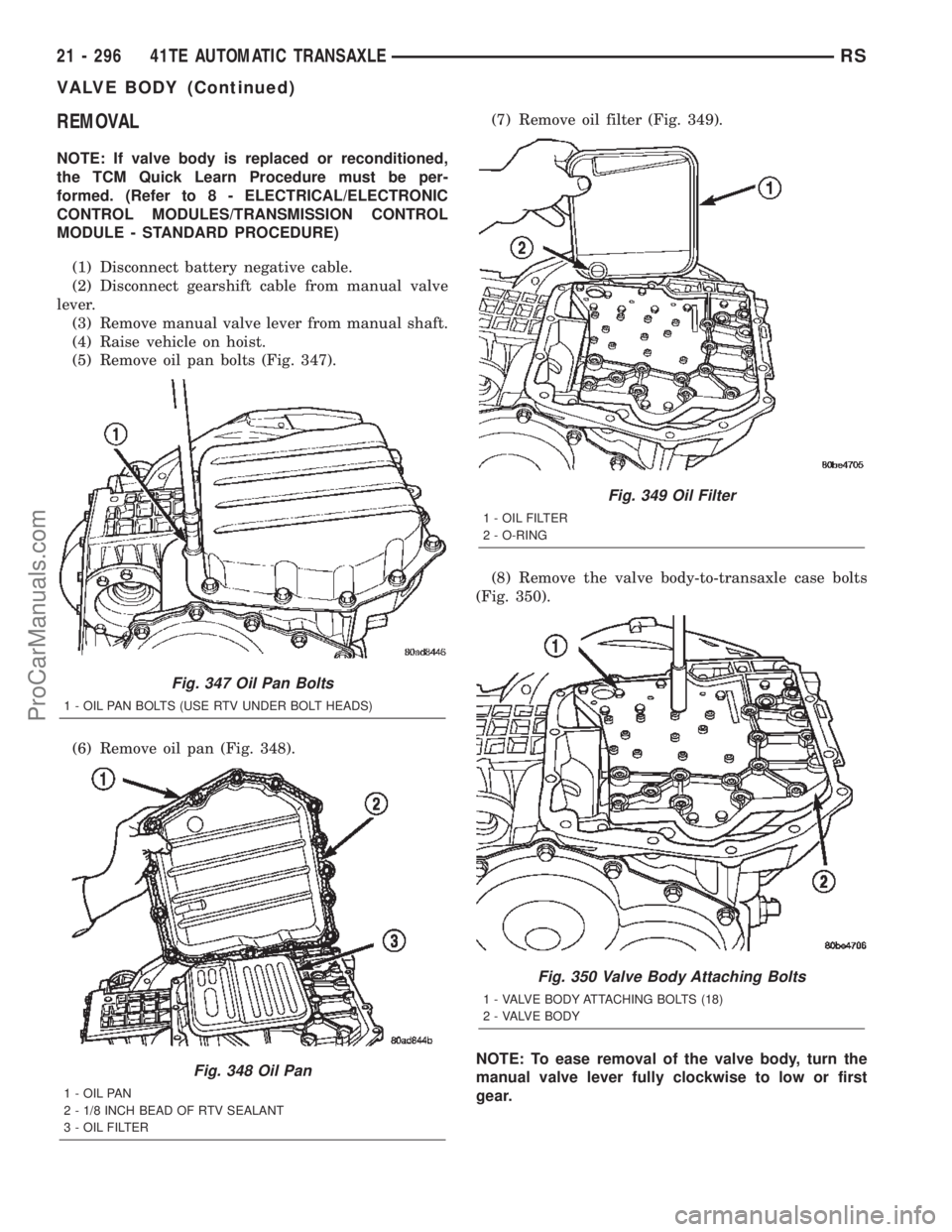
(5) Remove oil pan bolts (Fig. 347).
(6) Remove oil pan (Fig. 348).(7) Remove oil filter (Fig. 349).
(8) Remove the valve body-to-transaxle case bolts
(Fig. 350).
NOTE: To ease removal of the valve body, turn the
manual valve lever fully clockwise to low or first
gear.
Fig. 347 Oil Pan Bolts
1 - OIL PAN BOLTS (USE RTV UNDER BOLT HEADS)
Fig. 348 Oil Pan
1 - OIL PAN
2 - 1/8 INCH BEAD OF RTV SEALANT
3 - OIL FILTER
Fig. 349 Oil Filter
1 - OIL FILTER
2 - O-RING
Fig. 350 Valve Body Attaching Bolts
1 - VALVE BODY ATTACHING BOLTS (18)
2 - VALVE BODY
21 - 296 41TE AUTOMATIC TRANSAXLERS
VALVE BODY (Continued)
ProCarManuals.com