2002 CHRYSLER CARAVAN oil filter
[x] Cancel search: oil filterPage 1318 of 2399
DESCRIPTION - 3.8L
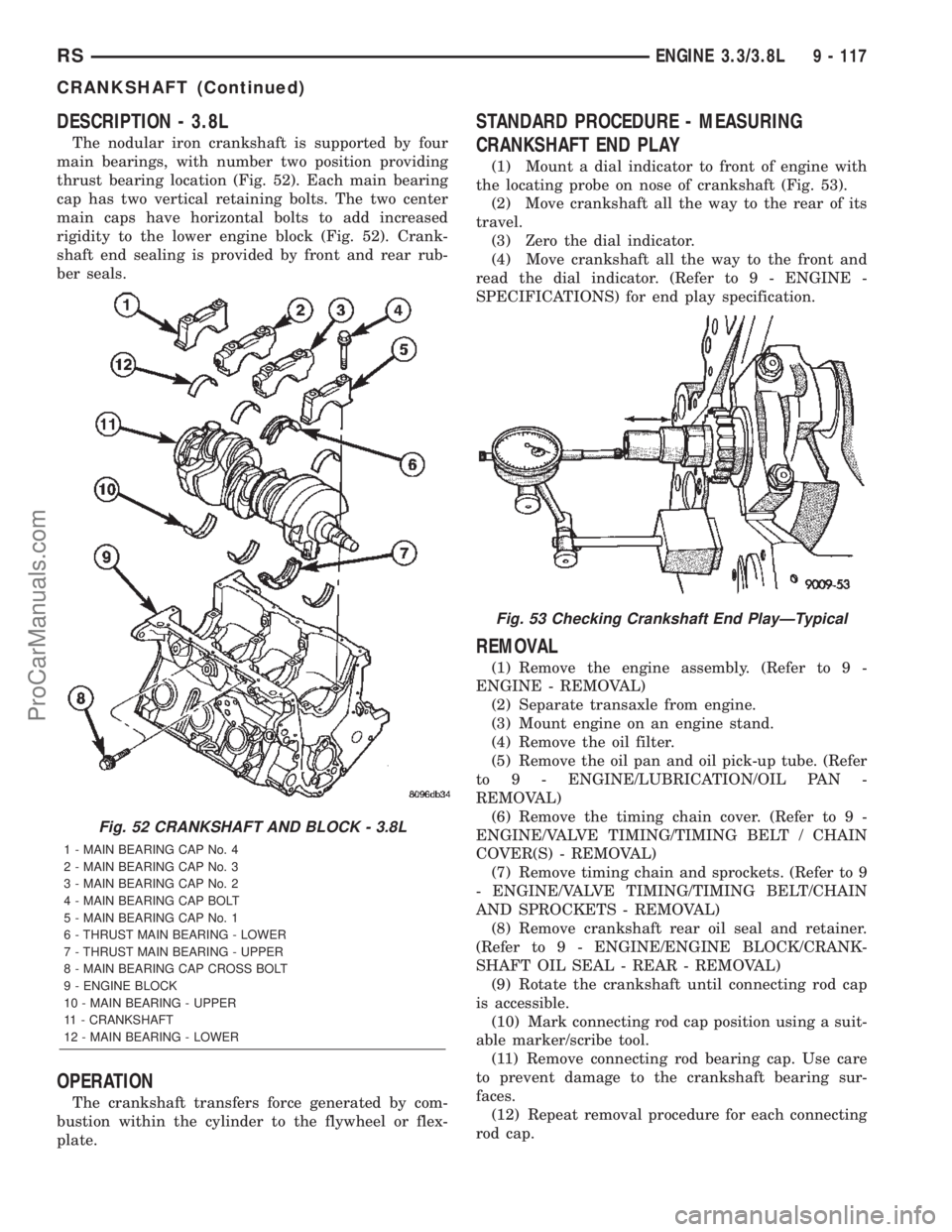
The nodular iron crankshaft is supported by four
main bearings, with number two position providing
thrust bearing location (Fig. 52). Each main bearing
cap has two vertical retaining bolts. The two center
main caps have horizontal bolts to add increased
rigidity to the lower engine block (Fig. 52). Crank-
shaft end sealing is provided by front and rear rub-
ber seals.
OPERATION
The crankshaft transfers force generated by com-
bustion within the cylinder to the flywheel or flex-
plate.
STANDARD PROCEDURE - MEASURING
CRANKSHAFT END PLAY
(1) Mount a dial indicator to front of engine with
the locating probe on nose of crankshaft (Fig. 53).
(2) Move crankshaft all the way to the rear of its
travel.
(3) Zero the dial indicator.
(4) Move crankshaft all the way to the front and
read the dial indicator. (Refer to 9 - ENGINE -
SPECIFICATIONS) for end play specification.
REMOVAL
(1) Remove the engine assembly. (Refer to 9 -
ENGINE - REMOVAL)
(2) Separate transaxle from engine.
(3) Mount engine on an engine stand.
(4) Remove the oil filter.
(5) Remove the oil pan and oil pick-up tube. (Refer
to 9 - ENGINE/LUBRICATION/OIL PAN -
REMOVAL)
(6) Remove the timing chain cover. (Refer to 9 -
ENGINE/VALVE TIMING/TIMING BELT / CHAIN
COVER(S) - REMOVAL)
(7) Remove timing chain and sprockets. (Refer to 9
- ENGINE/VALVE TIMING/TIMING BELT/CHAIN
AND SPROCKETS - REMOVAL)
(8) Remove crankshaft rear oil seal and retainer.
(Refer to 9 - ENGINE/ENGINE BLOCK/CRANK-
SHAFT OIL SEAL - REAR - REMOVAL)
(9) Rotate the crankshaft until connecting rod cap
is accessible.
(10) Mark connecting rod cap position using a suit-
able marker/scribe tool.
(11) Remove connecting rod bearing cap. Use care
to prevent damage to the crankshaft bearing sur-
faces.
(12) Repeat removal procedure for each connecting
rod cap.
Fig. 52 CRANKSHAFT AND BLOCK - 3.8L
1 - MAIN BEARING CAP No. 4
2 - MAIN BEARING CAP No. 3
3 - MAIN BEARING CAP No. 2
4 - MAIN BEARING CAP BOLT
5 - MAIN BEARING CAP No. 1
6 - THRUST MAIN BEARING - LOWER
7 - THRUST MAIN BEARING - UPPER
8 - MAIN BEARING CAP CROSS BOLT
9 - ENGINE BLOCK
10 - MAIN BEARING - UPPER
11 - CRANKSHAFT
12 - MAIN BEARING - LOWER
Fig. 53 Checking Crankshaft End PlayÐTypical
RSENGINE 3.3/3.8L9 - 117
CRANKSHAFT (Continued)
ProCarManuals.com
Page 1338 of 2399
RIGHT MOUNT
REMOVAL
(1) Remove air cleaner housing lid and clean air
hose from throttle body.
(2) Remove air cleaner element and housing.
(3) Disconnect make-up air hose from cylinder
head cover.
(4) Remove the load on the right engine mount by
carefully supporting the engine assembly with a floor
jack.
(5) Disconnect electrical harness support clips from
engine mount bracket.
(6) Remove the bolts attaching the engine mount
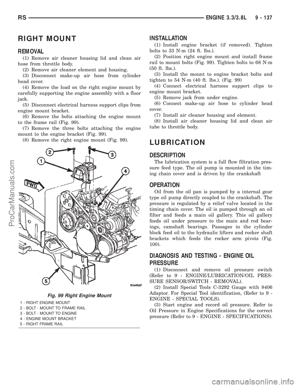
to the frame rail (Fig. 99).
(7) Remove the three bolts attaching the engine
mount to the engine bracket (Fig. 99).
(8) Remove the right engine mount (Fig. 99).
INSTALLATION
(1) Install engine bracket (if removed). Tighten
bolts to 33 N´m (24 ft. lbs.).
(2) Position right engine mount and install frame
rail to mount bolts (Fig. 99). Tighten bolts to 68 N´m
(50 ft. lbs.).
(3) Install the mount to engine bracket bolts and
tighten to 54 N´m (40 ft. lbs.). (Fig. 99)
(4) Connect electrical harness support clips to
engine mount bracket.
(5) Remove jack from under engine.
(6) Connect make-up air hose to cylinder head
cover.
(7) Install air cleaner housing and element.
(8) Install air cleaner housing lid and clean air
tube to throttle body.
LUBRICATION
DESCRIPTION
The lubrication system is a full flow filtration pres-
sure feed type. The oil pump is mounted in the tim-
ing chain cover and is driven by the crankshaft
OPERATION
Oil from the oil pan is pumped by a internal gear
type oil pump directly coupled to the crankshaft. The
pressure is regulated by a relief valve located in the
timing chain cover. The oil is pumped through an oil
filter and feeds a main oil gallery. This oil gallery
feeds oil under pressure to the main and rod bear-
ings, camshaft bearings. Passages in the cylinder
block feed oil to the hydraulic lifters and rocker shaft
brackets which feeds the rocker arm pivots (Fig.
100).
DIAGNOSIS AND TESTING - ENGINE OIL
PRESSURE
(1) Disconnect and remove oil pressure switch
(Refer to 9 - ENGINE/LUBRICATION/OIL PRES-
SURE SENSOR/SWITCH - REMOVAL).
(2) Install Special Tools C-3292 Gauge with 8406
Adaptor. For Special Tool identification, (Refer to 9 -
ENGINE - SPECIAL TOOLS).
(3) Start engine and record oil pressure. Refer to
Oil Pressure in Engine Specifications for the correct
pressure (Refer to 9 - ENGINE - SPECIFICATIONS).
Fig. 99 Right Engine Mount
1 - RIGHT ENGINE MOUNT
2 - BOLT - MOUNT TO FRAME RAIL
3 - BOLT - MOUNT TO ENGINE
4 - ENGINE MOUNT BRACKET
5 - RIGHT FRAME RAIL
RSENGINE 3.3/3.8L9 - 137
ProCarManuals.com
Page 1339 of 2399

OIL
STANDARD PROCEDURE
STANDARD PROCEDURE - ENGINE OIL AND
FILTER CHANGE
Change engine oil at mileage and time intervals
described in the Maintenance Schedule. (Refer to
LUBRICATION & MAINTENANCE/MAINTE-
NANCE SCHEDULES - DESCRIPTION)
WARNING: NEW OR USED ENGINE OIL CAN BE
IRRITATING TO THE SKIN. AVOID PROLONGED OR
REPEATED SKIN CONTACT WITH ENGINE OIL.
CONTAMINANTS IN USED ENGINE OIL, CAUSED BY
INTERNAL COMBUSTION, CAN BE HAZARDOUS TO
YOUR HEALTH. THOROUGHLY WASH EXPOSED
SKIN WITH SOAP AND WATER. DO NOT WASH
SKIN WITH GASOLINE, DIESEL FUEL, THINNER, OR
SOLVENTS, HEALTH PROBLEMS CAN RESULT. DO
NOT POLLUTE, DISPOSE OF USED ENGINE OIL
PROPERLY. CONTACT YOUR DEALER OR GOVERN-MENT AGENCY FOR LOCATION OF COLLECTION
CENTER IN YOUR AREA.
Run engine until achieving normal operating tem-
perature.
(1) Position the vehicle on a level surface and turn
engine off.
(2) Open hood, remove oil fill cap.
(3) Hoist and support vehicle on safety stands.
Refer to Hoisting and Jacking Recommendations.
(Refer to LUBRICATION & MAINTENANCE/HOIST-
ING - STANDARD PROCEDURE)
(4) Place a suitable drain pan under crankcase
drain (Fig. 101).
(5) Remove drain plug from crankcase (Fig. 101)
and allow oil to drain into pan. Inspect drain plug
threads for stretching or other damage. Replace
drain plug and gasket if damaged.
(6) Remove oil filter. (Refer to 9 - ENGINE/LUBRI-
CATION/OIL FILTER - REMOVAL)
(7) Install and tighten drain plug in crankcase.
(8) Install new oil filter. (Refer to 9 - ENGINE/LU-
BRICATION/OIL FILTER - INSTALLATION)
Fig. 100 Engine Oiling System
1 - OIL SUPPLY FOR BALL SOCKET THROUGH PUSH ROD 7 - OUTER ROTOR
2 - OIL SUPPLY PASSAGE FROM SHAFT TO ROCKER ARM 8 - INNER ROTOR
3 - ROCKER SHAFT 9 - RELIEF VALVE
4 - OIL FLOWS TO ONLY ONE PEDASTAL ON EACH HEAD; THIRD
FROM REAR ON RIGHT HEAD, THIRD FROM FRONT ON LEFT
HEAD10 - OIL PAN
5 - ROCKER SHAFT TOWER 11 - OIL SCREEN
6 - CRANKSHAFT 12 - OIL PUMP CASE
9 - 138 ENGINE 3.3/3.8LRS
LUBRICATION (Continued)
ProCarManuals.com
Page 1340 of 2399

(9) Lower vehicle and fill crankcase with specified
type and amount of engine oil. (Refer to LUBRICA-
TION & MAINTENANCE/FLUID TYPES -
DESCRIPTION)
(10) Install oil fill cap.
(11) Start engine and inspect for leaks.
(12) Stop engine and inspect oil level.
NOTE: Care should be exercised when disposing
used engine oil after it has been drained from a
vehicle engine. Refer to the WARNING listed above.
STANDARD PROCEDURE - ENGINE OIL LEVEL
CHECK
The best time to check engine oil level is after it
has sat overnight, or if the engine has been running,
allow the engine to be shut off for at least 5 minutes
before checking oil level.
Checking the oil while the vehicle is on level
ground will improve the accuracy of the oil level
reading (Fig. 102). Add only when the level is at or
below the ADD mark.
Fig. 102 Engine Oil Level Dipstick and Fill Locations
1 - COOLANT RECOVERY CONTAINER 3 - ENGINE OIL LEVEL DIPSTICK
2 - ENGINE OIL FILL CAP 4 - RADIATOR PRESSURE CAP
Fig. 101 Engine Oil Drain Plug and Oil Filter
1 - DRAIN PLUG
2 - OIL FILTER
RSENGINE 3.3/3.8L9 - 139
OIL (Continued)
ProCarManuals.com
Page 1341 of 2399
OIL COOLER & LINES
DESCRIPTION
An engine oil cooler is used on 3.3/3.8L engines
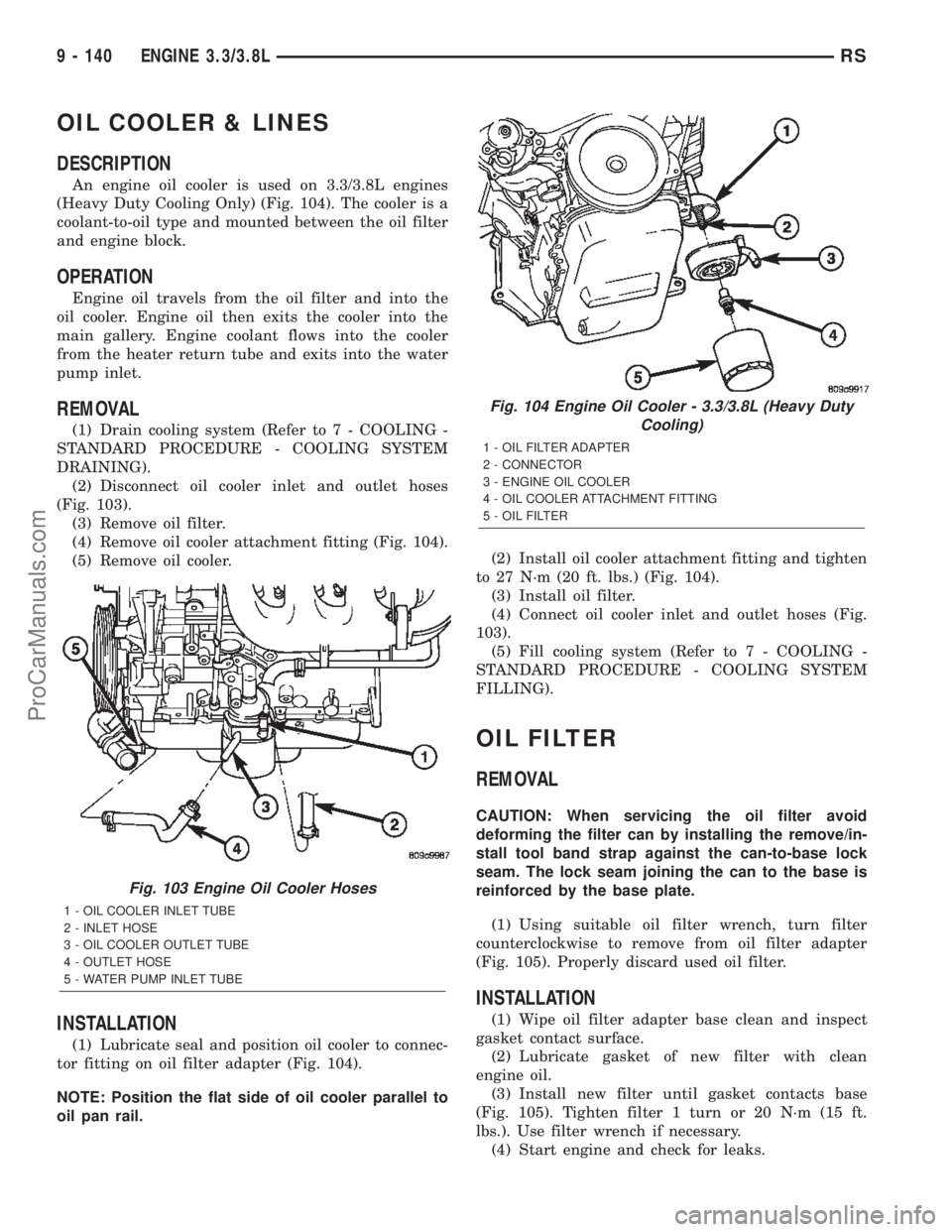
(Heavy Duty Cooling Only) (Fig. 104). The cooler is a
coolant-to-oil type and mounted between the oil filter
and engine block.
OPERATION
Engine oil travels from the oil filter and into the
oil cooler. Engine oil then exits the cooler into the
main gallery. Engine coolant flows into the cooler
from the heater return tube and exits into the water
pump inlet.
REMOVAL
(1) Drain cooling system (Refer to 7 - COOLING -
STANDARD PROCEDURE - COOLING SYSTEM
DRAINING).
(2) Disconnect oil cooler inlet and outlet hoses
(Fig. 103).
(3) Remove oil filter.
(4) Remove oil cooler attachment fitting (Fig. 104).
(5) Remove oil cooler.
INSTALLATION
(1) Lubricate seal and position oil cooler to connec-
tor fitting on oil filter adapter (Fig. 104).
NOTE: Position the flat side of oil cooler parallel to
oil pan rail.(2) Install oil cooler attachment fitting and tighten
to 27 N´m (20 ft. lbs.) (Fig. 104).
(3) Install oil filter.
(4) Connect oil cooler inlet and outlet hoses (Fig.
103).
(5) Fill cooling system (Refer to 7 - COOLING -
STANDARD PROCEDURE - COOLING SYSTEM
FILLING).
OIL FILTER
REMOVAL
CAUTION: When servicing the oil filter avoid
deforming the filter can by installing the remove/in-
stall tool band strap against the can-to-base lock
seam. The lock seam joining the can to the base is
reinforced by the base plate.
(1) Using suitable oil filter wrench, turn filter
counterclockwise to remove from oil filter adapter
(Fig. 105). Properly discard used oil filter.
INSTALLATION
(1) Wipe oil filter adapter base clean and inspect
gasket contact surface.
(2) Lubricate gasket of new filter with clean
engine oil.
(3) Install new filter until gasket contacts base
(Fig. 105). Tighten filter 1 turn or 20 N´m (15 ft.
lbs.). Use filter wrench if necessary.
(4) Start engine and check for leaks.
Fig. 103 Engine Oil Cooler Hoses
1 - OIL COOLER INLET TUBE
2 - INLET HOSE
3 - OIL COOLER OUTLET TUBE
4 - OUTLET HOSE
5 - WATER PUMP INLET TUBE
Fig. 104 Engine Oil Cooler - 3.3/3.8L (Heavy Duty
Cooling)
1 - OIL FILTER ADAPTER
2 - CONNECTOR
3 - ENGINE OIL COOLER
4 - OIL COOLER ATTACHMENT FITTING
5 - OIL FILTER
9 - 140 ENGINE 3.3/3.8LRS
ProCarManuals.com
Page 1342 of 2399
OIL FILTER ADAPTER
REMOVAL
(1) Raise vehicle on hoist.
(2) Remove the oil filter.
(3) Disconnect oil pressure switch electrical con-
nector.
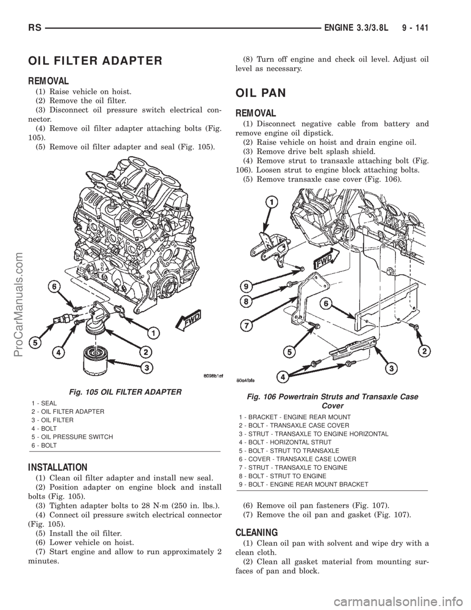
(4) Remove oil filter adapter attaching bolts (Fig.
105).
(5) Remove oil filter adapter and seal (Fig. 105).
INSTALLATION
(1) Clean oil filter adapter and install new seal.
(2) Position adapter on engine block and install
bolts (Fig. 105).
(3) Tighten adapter bolts to 28 N´m (250 in. lbs.).
(4) Connect oil pressure switch electrical connector
(Fig. 105).
(5) Install the oil filter.
(6) Lower vehicle on hoist.
(7) Start engine and allow to run approximately 2
minutes.(8) Turn off engine and check oil level. Adjust oil
level as necessary.
OIL PAN
REMOVAL
(1) Disconnect negative cable from battery and
remove engine oil dipstick.
(2) Raise vehicle on hoist and drain engine oil.
(3) Remove drive belt splash shield.
(4) Remove strut to transaxle attaching bolt (Fig.
106). Loosen strut to engine block attaching bolts.
(5) Remove transaxle case cover (Fig. 106).
(6) Remove oil pan fasteners (Fig. 107).
(7) Remove the oil pan and gasket (Fig. 107).
CLEANING
(1) Clean oil pan with solvent and wipe dry with a
clean cloth.
(2) Clean all gasket material from mounting sur-
faces of pan and block.
Fig. 105 OIL FILTER ADAPTER
1 - SEAL
2 - OIL FILTER ADAPTER
3 - OIL FILTER
4 - BOLT
5 - OIL PRESSURE SWITCH
6 - BOLTFig. 106 Powertrain Struts and Transaxle Case
Cover
1 - BRACKET - ENGINE REAR MOUNT
2 - BOLT - TRANSAXLE CASE COVER
3 - STRUT - TRANSAXLE TO ENGINE HORIZONTAL
4 - BOLT - HORIZONTAL STRUT
5 - BOLT - STRUT TO TRANSAXLE
6 - COVER - TRANSAXLE CASE LOWER
7 - STRUT - TRANSAXLE TO ENGINE
8 - BOLT - STRUT TO ENGINE
9 - BOLT - ENGINE REAR MOUNT BRACKET
RSENGINE 3.3/3.8L9 - 141
ProCarManuals.com
Page 1344 of 2399
INSTALLATION
(1) Clean relief valve, spring and bore.
NOTE: Lubricate relief valve with clean engine oil
before installing.
(2) Install relief valve and spring into housing.
(3) Install new retainer cap until flush with seal-
ing surface.
(4) Install oil pan (Refer to 9 - ENGINE/LUBRI-
CATION/OIL PAN - INSTALLATION).
(5) Fill crankcase with proper oil to correct level.
OIL PRESSURE SWITCH
DESCRIPTION
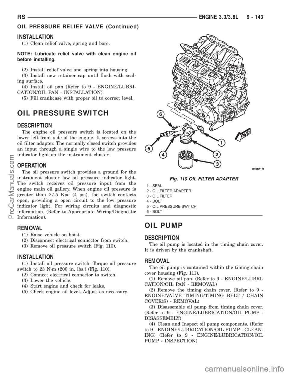
The engine oil pressure switch is located on the
lower left front side of the engine. It screws into the
oil filter adapter. The normally closed switch provides
an input through a single wire to the low pressure
indicator light on the instrument cluster.
OPERATION
The oil pressure switch provides a ground for the
instrument cluster low oil pressure indicator light.
The switch receives oil pressure input from the
engine main oil gallery. When engine oil pressure is
greater than 27.5 Kpa (4 psi), the switch contacts
open, providing a open circuit to the low pressure
indicator light. For wiring circuits and diagnostic
information, (Refer to Appropriate Wiring/Diagnostic
Information).
REMOVAL
(1) Raise vehicle on hoist.
(2) Disconnect electrical connector from switch.
(3) Remove oil pressure switch (Fig. 110).
INSTALLATION
(1) Install oil pressure switch. Torque oil pressure
switch to 23 N´m (200 in. lbs.) (Fig. 110).
(2) Connect electrical connector to switch.
(3) Lower the vehicle.
(4) Start engine and check for leaks.
(5) Check engine oil level. Adjust as necessary.
OIL PUMP
DESCRIPTION
The oil pump is located in the timing chain cover.
It is driven by the crankshaft.
REMOVAL
The oil pump is contained within the timing chain
cover housing (Fig. 111).
(1) Remove oil pan. (Refer to 9 - ENGINE/LUBRI-
CATION/OIL PAN - REMOVAL)
(2) Remove the timing chain cover. (Refer to 9 -
ENGINE/VALVE TIMING/TIMING BELT / CHAIN
COVER(S) - REMOVAL)
(3) Disassemble oil pump from timing chain cover.
(Refer to 9 - ENGINE/LUBRICATION/OIL PUMP -
DISASSEMBLY)
(4) Clean and Inspect oil pump components. (Refer
to 9 - ENGINE/LUBRICATION/OIL PUMP - CLEAN-
ING) (Refer to 9 - ENGINE/LUBRICATION/OIL
PUMP - INSPECTION)
Fig. 110 OIL FILTER ADAPTER
1 - SEAL
2 - OIL FILTER ADAPTER
3 - OIL FILTER
4 - BOLT
5 - OIL PRESSURE SWITCH
6 - BOLT
RSENGINE 3.3/3.8L9 - 143
OIL PRESSURE RELIEF VALVE (Continued)
ProCarManuals.com
Page 1363 of 2399
INSTALLATION
INSTALLATION.......................47
INSTALLATION.......................48
OIL PRESSURE SENSOR/SWITCH
DESCRIPTION.........................48
REMOVAL.............................48
INSTALLATION.........................48
OIL TEMPERATURE SENSOR
DESCRIPTION.........................48
REMOVAL.............................48
INSTALLATION.........................48
OIL PRESSURE RELIEF VALVE
DESCRIPTION.........................49
REMOVAL.............................49
INSTALLATION.........................49
OIL COOLER & LINES
REMOVAL.............................50
INSTALLATION.........................50
OIL FILTER
DESCRIPTION.........................51
REMOVAL.............................51
INSTALLATION.........................51
OIL JET
DESCRIPTION.........................52
REMOVAL.............................52
INSTALLATION.........................52
INTAKE MANIFOLD
DESCRIPTION.........................52
REMOVAL.............................52INSTALLATION.........................52
VALVE TIMING
STANDARD PROCEDURE - LOCKING ENGINE
90É AFTER TDC.......................53
BALANCE SHAFT
DESCRIPTION.........................54
OPERATION...........................54
REMOVAL.............................55
INSTALLATION.........................55
TIMING BELT / CHAIN COVER(S)
REMOVAL
REMOVAL - TIMING BELT OUTER COVER . . 56
REMOVAL - TIMING BELT INNER COVER . . . 56
INSTALLATION
INSTALLATION - TIMING BELT OUTER
COVER.............................56
INSTALLATION - TIMING BELT INNER
COVER.............................57
TIMING BELT IDLER PULLEY
REMOVAL.............................58
INSTALLATION.........................58
TMNG BELT/CHAIN TENSIONER
REMOVAL.............................59
INSTALLATION.........................59
ADJUSTMENTS
ADJUSTMENT - TIMING BELT TENSIONER . 60
TIMING BELT/CHAIN AND SPROCKETS
REMOVAL.............................60
INSTALLATION.........................61
ENGINE 2.5L TURBO DIESEL
DESCRIPTION
DESCRIPTION - 2.5L COMMON RAIL DIESEL
ENGINE
This 2.5 Liter (2500cc) four-cylinder ªcommon railº
direct injection engine is an in-line overhead valve
diesel engine. This engine utilizes a cast iron cylin-
der block and an aluminum cylinder head. The
engine is turbocharged and intercooled. The engine
also has four valves per cylinder and dual overhead
camshafts (Fig. 1).
DESCRIPTION SPECIFICATION
Displacement 2.5L (2499 cc)
Bore 92.00
Stroke 94.00
Compression Ratio 17.5:1
Vacuum at Idle 685.8 mm/Hg (27.0
In/Hg)
Belt Tension Automatic Belt Tensioner
DESCRIPTION SPECIFICATION
Thermostat Opening 80ÉC 2ÉC
Generator Rating Denso 12V-95A
Cooling System Capacity 13.8 Liters W/O Auxiliary
Heater
16.6 Liters With Auxiliary
Heater
Engine Oil Capacity 6.0L W/Filter Change
Timing System Belt Driven Camshafts In
Cylinder Head Cover
Air Intake Dry Filter
Fuel Feed Vane Pump Incorporated
In Injection Pump
Fuel System Direct Fuel Injection
Combustion Cycle 4 Stroke
Cooling System Water Cooling
Injection Pump Rotary Pump and
Electronically Managed
Lubrication Pressure Lubricated By
Rotary Pump
Engine Rotation Clockwise Viewed From
Front Cover
9a - 2 ENGINERG
ProCarManuals.com