2002 CHRYSLER CARAVAN ESP
[x] Cancel search: ESPPage 1966 of 2399
lines. Radial force measurements above the reference
value may not always result in a ride disturbance,
nor do they automatically mean the assembly compo-
nents are out of specification. Do not replace compo-
nents based on radial force values alone. Balancing,
runout diagnosis, re-indexing, and subjective road
testing must be performed as outlined in previous
sections of this diagnosis and testing procedure.
Use the Radial Force equipment to identify suspect
assemblies and minimize the radial forces. After all
suspect assemblies are optimized, reinstall the
assemblies and road test the vehicle. If a disturbance
still exists and all other vibration diagnostic proce-
dures have been completed, replace one tire or one
wheel at a time, starting with the assembly having
the highest force variation. Be sure to minimize each
new assembly. Road test the vehicle following each
replacement. Continue this process until the distur-
bance is resolved.
NOTE: When using Radial Force equipment, it is
critically important to set proper tire inflation pres-
sure and ensure centering of the wheel on the
equipment spindle.
RADIAL FORCE VARIATION REFERENCE
VALUES
DESCRIPTION SPECIFICATION
Total Radial Force
Variation (RFV)Less Than 22 Lbs. 2
Lbs.
Radial First Harmonic
(R1H)Less Than 16 Lbs. 2
Lbs.
Radial Second Harmonic
(R2H)Less Than 12 Lbs. 2
Lbs.
STANDARD PROCEDURE
STANDARD PROCEDURE - TIRE AND WHEEL
BALANCE
NOTE: Balance equipment must be calibrated and
maintained per equipment manufacturer's specifica-
tions.
Wheel balancing can be accomplished with either
on-vehicle or off-vehicle equipment.
NOTE: If using on-vehicle balancing equipment, on
the driving axle, remove the opposite wheel and tire
assembly.
It is recommended that a two-plane dynamic bal-
ancer be used when a wheel and tire assemblyrequires balancing. A static balancer should only be
used when a two-plane balancer is not available.
Balance wheel and tire assemblies dynamically and
statically to less than 0.25 (
1¤4) ounce.
For static balancing, find location of heavy spot
causing imbalance. Counter balance wheel directly
opposite the heavy spot. Determine weight required
to counterbalance the area of imbalance. Place half of
this weight on theinnerrim flange and the other
half on theouterrim flange (Fig. 8).
For dynamic balancing, the balance equipment is
designed to indicate the location and amount of
weight to be applied to both the inner and outer rim
flanges (Fig. 9).
The aluminum wheels on this vehicle use a unique
wheel weight (Fig. 10). This wheel weight is designed
to fit the contoured surface of the wheel (Fig. 10).
When balancing an aluminum wheel, this wheel
weight must be used. Do not use any other type of
wheel weight. It will not properly fit the contour of
the wheel.
Always verify the Balance. When using off-vehicle
equipment, rotate assembly 180 degrees on balance
equipment to verify balance. Variation should not be
more than 0.125 (
1¤8) ounce. If variation is more than
0.125 ounce, balancing equipment could be malfunc-
tioning.
If difficult to balance, break down the wheel and
tire assembly and check for loose debris inside tire.
Prior to disassembly, mark (index) the tire at the
valve stem. Use this mark in order to remount the
tire in its original orientation with respect to the
wheel.
STANDARD PROCEDURE - TIRE AND WHEEL
MATCH MOUNTING
Wheels and tires are match mounted at the factory.
This means that the high spot of the tire is matched
to the low spot on the wheel rim. This technique is
used to reduce runout in the wheel and tire assem-
bly. The high spot on the tire is marked with a paint
mark or a bright colored adhesive label on the out-
board sidewall. The low spot on the wheel is identi-
fied with a label on the outside of the rim and a dot
or line in the drop well area of the rim (inside where
the tire mounts). If the outside label has been
removed, the tire will have to be removed to locate
the dot or line on the inside of the rim. The tire can
then be match mounted to the tire.
Information on match mounting the tire to the
wheel can be found in Tire and Wheel Runout/Match
Mounting, items (2) through (5), within Diagnosis
And Testing - Tire And Wheel Vibration. (Refer to 22
- TIRES/WHEELS - DIAGNOSIS AND TESTING)
RSTIRES/WHEELS22-5
TIRES/WHEELS (Continued)
ProCarManuals.com
Page 1968 of 2399
STANDARD PROCEDURE - TIRE AND WHEEL
ROTATION
NON-DIRECTIONAL TREAD PATTERN TIRES
Tires on the front and rear axles operate at differ-
ent loads and perform different functions. For these
reasons, they wear at unequal rates, and tend to
develop irregular wear patterns. These effects can be
reduced by timely rotation of tires. The benefits of
rotation are especially worthwhile. Rotation will
increase tread life, help to maintain mud, snow, and
wet traction levels, and contribute to a smooth, quiet
ride.
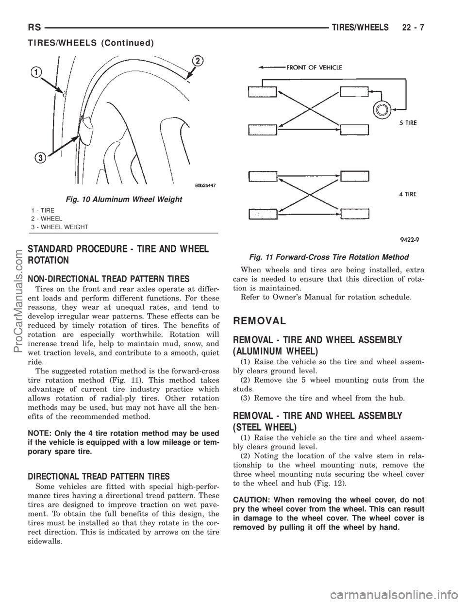
The suggested rotation method is the forward-cross
tire rotation method (Fig. 11). This method takes
advantage of current tire industry practice which
allows rotation of radial-ply tires. Other rotation
methods may be used, but may not have all the ben-
efits of the recommended method.
NOTE: Only the 4 tire rotation method may be used
if the vehicle is equipped with a low mileage or tem-
porary spare tire.
DIRECTIONAL TREAD PATTERN TIRES
Some vehicles are fitted with special high-perfor-
mance tires having a directional tread pattern. These
tires are designed to improve traction on wet pave-
ment. To obtain the full benefits of this design, the
tires must be installed so that they rotate in the cor-
rect direction. This is indicated by arrows on the tire
sidewalls.When wheels and tires are being installed, extra
care is needed to ensure that this direction of rota-
tion is maintained.
Refer to Owner's Manual for rotation schedule.
REMOVAL
REMOVAL - TIRE AND WHEEL ASSEMBLY
(ALUMINUM WHEEL)
(1) Raise the vehicle so the tire and wheel assem-
bly clears ground level.
(2) Remove the 5 wheel mounting nuts from the
studs.
(3) Remove the tire and wheel from the hub.
REMOVAL - TIRE AND WHEEL ASSEMBLY
(STEEL WHEEL)
(1) Raise the vehicle so the tire and wheel assem-
bly clears ground level.
(2) Noting the location of the valve stem in rela-
tionship to the wheel mounting nuts, remove the
three wheel mounting nuts securing the wheel cover
to the wheel and hub (Fig. 12).
CAUTION: When removing the wheel cover, do not
pry the wheel cover from the wheel. This can result
in damage to the wheel cover. The wheel cover is
removed by pulling it off the wheel by hand.
Fig. 10 Aluminum Wheel Weight
1 - TIRE
2 - WHEEL
3 - WHEEL WEIGHT
Fig. 11 Forward-Cross Tire Rotation Method
RSTIRES/WHEELS22-7
TIRES/WHEELS (Continued)
ProCarManuals.com
Page 2042 of 2399
SIDE VIEW MIRROR GLASS
REMOVAL
WARNING: ALWAYS WEAR EYE AND HAND PRO-
TECTION WHEN SERVICING THE MIRROR ASSEM-
BLY. FAILURE TO OBSERVE THESE WARNINGS
MAY RESULT IN PERSONAL INJURY FROM BRO-
KEN GLASS.
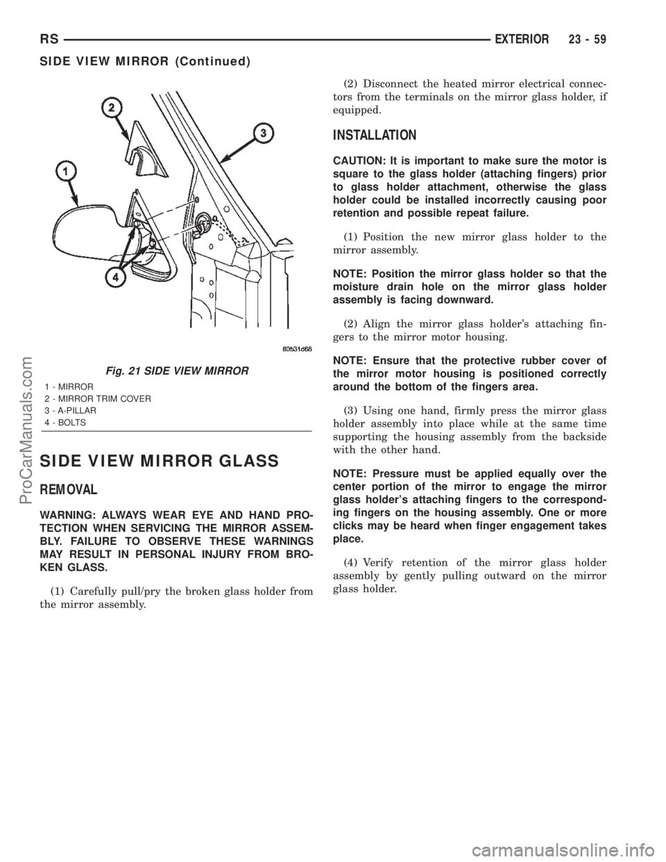
(1) Carefully pull/pry the broken glass holder from
the mirror assembly.(2) Disconnect the heated mirror electrical connec-
tors from the terminals on the mirror glass holder, if
equipped.
INSTALLATION
CAUTION: It is important to make sure the motor is
square to the glass holder (attaching fingers) prior
to glass holder attachment, otherwise the glass
holder could be installed incorrectly causing poor
retention and possible repeat failure.
(1) Position the new mirror glass holder to the
mirror assembly.
NOTE: Position the mirror glass holder so that the
moisture drain hole on the mirror glass holder
assembly is facing downward.
(2) Align the mirror glass holder's attaching fin-
gers to the mirror motor housing.
NOTE: Ensure that the protective rubber cover of
the mirror motor housing is positioned correctly
around the bottom of the fingers area.
(3) Using one hand, firmly press the mirror glass
holder assembly into place while at the same time
supporting the housing assembly from the backside
with the other hand.
NOTE: Pressure must be applied equally over the
center portion of the mirror to engage the mirror
glass holder's attaching fingers to the correspond-
ing fingers on the housing assembly. One or more
clicks may be heard when finger engagement takes
place.
(4) Verify retention of the mirror glass holder
assembly by gently pulling outward on the mirror
glass holder.
Fig. 21 SIDE VIEW MIRROR
1 - MIRROR
2 - MIRROR TRIM COVER
3 - A-PILLAR
4 - BOLTS
RSEXTERIOR23-59
SIDE VIEW MIRROR (Continued)
ProCarManuals.com
Page 2245 of 2399
FRONT CONTROL PANEL
The front control panel and integral computer is
mounted in the instrument panel.
The instrument panel mounted control and inte-
gral computer contains:
²a power button which allows the system to be
completely turned off.
²rear window defogger on/off switch.
²slide controls for completely independent side-to-
side temperature control of the discharge air. The full
range of temperature that the system can produce in
any mode is available on either side of the vehicle by
independently positioning the slide controls on the
instrument panel.
²air recirculation button. The Recirculate button
contains an LED that illuminates to show when the
function is in operation.
²an air conditioning button that allows the com-
pressor to be turned on/off. The Snowflake button
contains an LED that illuminates to shown when the
function is in operation.
²rotary knobs for front and rear fan speed selec-
tion.
²a rotary knob for mode control.
REAR CONTROL PANEL
A rear control panel centrally mounted on the
headliner has a rotary adjustment for temperature
and fan speed control of the rear unit by intermedi-
ate seat passengers when the front control rear knob
is set to the rear position.
DESCRIPTION - THREE ZONE AUTOMATIC
TEMPERATURE CONTROL
The Three-Zone Automatic Temperature Control
(ATC) allows occupants to select a comfort tempera-
ture, which is the perceived temperature level not
the actual passenger compartment air temperature.
The Three Zone Automatic Temperature Control
system includes a dust and odor air filter. The filter
element is the same size as the air conditioning evap-
orator to ensure ample capacity. A door at the base of
the heater and air conditioning housing below the
glove box provides easy access to the filter element.
The ATC computer utilizes integrated circuitry and
information carried on the Programmable Communi-
cations Interface (PCI) data bus network to monitor
many sensors and switch inputs throughout the vehi-
cle. In response to those inputs, the internal circuitry
and programming of the ATC computer allow it to
control electronic functions and features of the ATC
system. The inputs to the ATC computer are:
²Vehicle Speed/Engine RPM± The ATC com-
puter monitors engine RPM, vehicle speed and Man-
ifold Absolute Pressure information from the PCM.²Coolant Temperature± ATC computer moni-
tors Coolant temperature received from the PCM and
converts it to degrees Fahrenheit.
²Ambient Temperature± ATC computer moni-
tors Ambient temperature from the Compass Mini
Trip Computer (CMTC) and converts it to degrees
Fahrenheit.
²Engine Miscellaneous Sensor Status±ATC
computer monitors A/C disable information from the
PCM.
²Refrigerant Pressure± ATC computer moni-
tors Barometric Pressure, Intake Air Temperature,
High Side Pressure and Methanol Content as broad-
cast by the PCM.
²Door Ajar Status± The ATC computer moni-
tors Driver Front Door, Passenger Front Door, Left
Rear Door, Right Rear Door and Liftgate ajar infor-
mation, as identified by the Body Control Module
(BCM), to determine if all in-car temperatures should
be maintained.
²Dimming± The ATC computer monitors dim-
ming status from the BCM to determine the required
level of brightness and will dim accordingly.
²Vehicle Odometer± The ATC computer moni-
tors the vehicle odometer information from the BCM
to prevent flashing the VF tube icons if the manual
motor calibration or manual cool down tests have
failed. Flashing of the display icons will cease when
the vehicle odometer is greater than 3 miles.
²English Metric± The ATC computer monitors
the English/Metric information broadcast by the
CMTC. The set temp displays for both the front and
rear control heads will be set accordingly.
²Vehicle Identification Number± The ATC
computer monitors the last eight characters of the
VIN broadcast by the PCM and compares it to the
information stored in EEPROM. If it is different, the
new number will be stored over the old one and a
motor calibration shall be initiated.
²A/C System Information± The ATC computer
will send a message for Evaporator Temperature too
Low, Fan Blower Relay status, Evaporator Sensor
Failure, Rear Window Defogger Relay and A/C Select.
FRONT CONTROL PANEL
The front control panel and integral computer is
mounted in the instrument panel.
The instrument panel mounted control and inte-
gral computer contains:
²A power button which allows the system to be
completely turned off. The display is blank when the
system is off.
²Three rocker switches that select comfort tem-
peratures from 15É to 30É C (59É to 85É F), which are
shown in the vacuum-fluorescent digital control dis-
play. If the set temp is 59 and the down button is
24 - 2 HEATING & AIR CONDITIONINGRS
HEATING & AIR CONDITIONING (Continued)
ProCarManuals.com
Page 2253 of 2399
A/C PRESSURE TRANSDUCER
DESCRIPTION - A/C PRESSURE TRANSDUCER
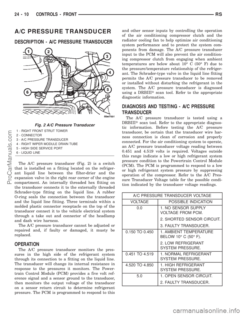
The A/C pressure transducer (Fig. 2) is a switch
that is installed on a fitting located on the refriger-
ant liquid line between the filter-drier and the
expansion valve in the right rear corner of the engine
compartment. An internally threaded hex fitting on
the transducer connects it to the externally threaded
Schrader-type fitting on the liquid line. A rubber
O-ring seals the connection between the transducer
and the liquid line fitting. Three terminals within a
molded plastic connector receptacle on the top of the
transducer connect it to the vehicle electrical system
through a take out and connector of the headlamp
and dash wire harness.
The A/C pressure transducer cannot be adjusted or
repaired and, if faulty or damaged, it musty be
replaced.
OPERATION
The A/C pressure transducer monitors the pres-
sures in the high side of the refrigerant system
through its connection to a fitting on the liquid line.
The transducer will change its internal resistance in
response to the pressures it monitors. The Power-
train Control Module (PCM) provides a five volt ref-
erence signal and a sensor ground to the transducer,
then monitors the output voltage of the transducer
on a sensor return circuit to determine refrigerant
pressure. The PCM is programmed to respond to thisand other sensor inputs by controlling the operation
of the air conditioning compressor clutch and the
radiator cooling fan to help optimize air conditioning
system performance and to protect the system com-
ponents from damage. The A/C pressure transducer
input to the PCM will also prevent the air condition-
ing compressor clutch from engaging when ambient
temperatures are below about 10É C (50É F) due to
the pressure/temperature relationship of the refriger-
ant. The Schrader-type valve in the liquid line fitting
permits the A/C pressure transducer to be removed
or installed without disturbing the refrigerant in the
system. The A/C pressure transducer is diagnosed
using a DRBIIItscan tool. Refer to the appropriate
diagnostic information.
DIAGNOSIS AND TESTING - A/C PRESSURE
TRANSDUCER
The A/C pressure transducer is tested using a
DRBIIItscan tool. Refer to the appropriate diagnos-
tic information. Before testing the A/C pressure
transducer, be certain that the transducer wire har-
ness connection is clean of corrosion and properly
connected. For the air conditioning system to operate,
an A/C pressure transducer voltage reading between
0.451 and 4.519 volts is required. Voltages outside
this range indicate a low or high refrigerant system
pressure condition to the Powertrain Control Module
(PCM). The PCM is programmed to respond to a low
or high refrigerant system pressure by suppressing
operation of the compressor. Refer to the A/C Pres-
sure Transducer Voltage table for the possible condi-
tion indicated by the transducer voltage readings.
A/C PRESSURE TRANSDUCER VOLTAGE
VOLTAGE POSSIBLE INDICATION
0.0 1. NO SENSOR SUPPLY
VOLTAGE FROM PCM.
2. SHORTED SENSOR CIRCUIT.
3. FAULTY TRANSDUCER.
0.150 TO 0.450 1. AMBIENT TEMPERATURE
BELOW 10É C (50É F).
2. LOW REFRIGERANT
SYSTEM PRESSURE.
0.451 TO 4.519 1. NORMAL REFRIGERANT
SYSTEM PRESSURE.
4.520 TO 4.850 1. HIGH REFRIGERANT
SYSTEM PRESSURE.
5.0 1. OPEN SENSOR CIRCUIT.
2. FAULTY TRANSDUCER.
Fig. 2 A/C Pressure Transducer
1 - RIGHT FRONT STRUT TOWER
2 - CONNECTOR
3 - A/C PRESSURE TRANSDUCER
4 - RIGHT WIPER MODULE DRAIN TUBE
5 - HIGH SIDE SERVICE PORT
6 - LIQUID LINE
24 - 10 CONTROLS - FRONTRS
ProCarManuals.com
Page 2266 of 2399
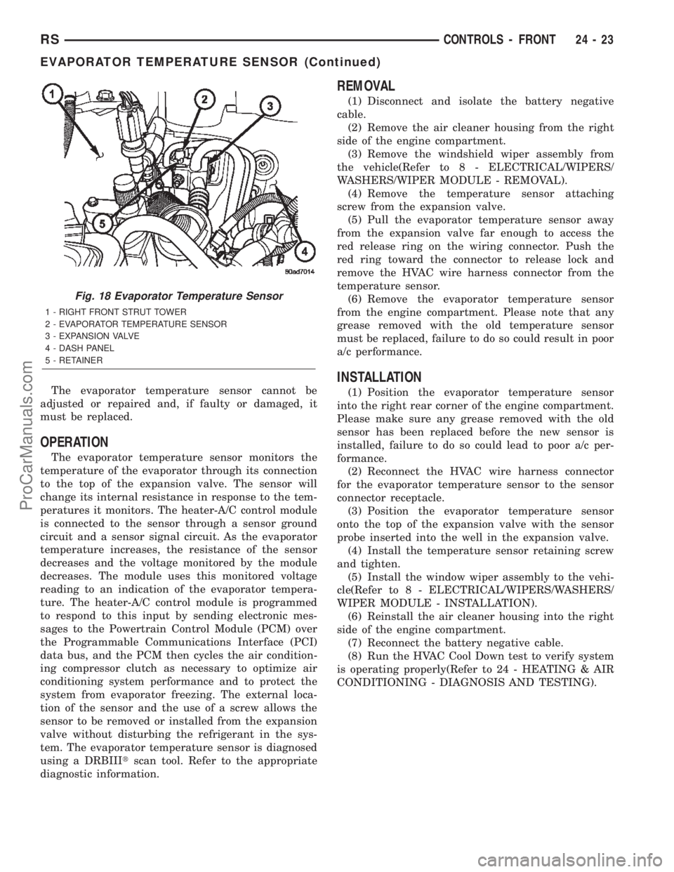
The evaporator temperature sensor cannot be
adjusted or repaired and, if faulty or damaged, it
must be replaced.
OPERATION
The evaporator temperature sensor monitors the
temperature of the evaporator through its connection
to the top of the expansion valve. The sensor will
change its internal resistance in response to the tem-
peratures it monitors. The heater-A/C control module
is connected to the sensor through a sensor ground
circuit and a sensor signal circuit. As the evaporator
temperature increases, the resistance of the sensor
decreases and the voltage monitored by the module
decreases. The module uses this monitored voltage
reading to an indication of the evaporator tempera-
ture. The heater-A/C control module is programmed
to respond to this input by sending electronic mes-
sages to the Powertrain Control Module (PCM) over
the Programmable Communications Interface (PCI)
data bus, and the PCM then cycles the air condition-
ing compressor clutch as necessary to optimize air
conditioning system performance and to protect the
system from evaporator freezing. The external loca-
tion of the sensor and the use of a screw allows the
sensor to be removed or installed from the expansion
valve without disturbing the refrigerant in the sys-
tem. The evaporator temperature sensor is diagnosed
using a DRBIIItscan tool. Refer to the appropriate
diagnostic information.
REMOVAL
(1) Disconnect and isolate the battery negative
cable.
(2) Remove the air cleaner housing from the right
side of the engine compartment.
(3) Remove the windshield wiper assembly from
the vehicle(Refer to 8 - ELECTRICAL/WIPERS/
WASHERS/WIPER MODULE - REMOVAL).
(4) Remove the temperature sensor attaching
screw from the expansion valve.
(5) Pull the evaporator temperature sensor away
from the expansion valve far enough to access the
red release ring on the wiring connector. Push the
red ring toward the connector to release lock and
remove the HVAC wire harness connector from the
temperature sensor.
(6) Remove the evaporator temperature sensor
from the engine compartment. Please note that any
grease removed with the old temperature sensor
must be replaced, failure to do so could result in poor
a/c performance.
INSTALLATION
(1) Position the evaporator temperature sensor
into the right rear corner of the engine compartment.
Please make sure any grease removed with the old
sensor has been replaced before the new sensor is
installed, failure to do so could lead to poor a/c per-
formance.
(2) Reconnect the HVAC wire harness connector
for the evaporator temperature sensor to the sensor
connector receptacle.
(3) Position the evaporator temperature sensor
onto the top of the expansion valve with the sensor
probe inserted into the well in the expansion valve.
(4) Install the temperature sensor retaining screw
and tighten.
(5) Install the window wiper assembly to the vehi-
cle(Refer to 8 - ELECTRICAL/WIPERS/WASHERS/
WIPER MODULE - INSTALLATION).
(6) Reinstall the air cleaner housing into the right
side of the engine compartment.
(7) Reconnect the battery negative cable.
(8) Run the HVAC Cool Down test to verify system
is operating properly(Refer to 24 - HEATING & AIR
CONDITIONING - DIAGNOSIS AND TESTING).
Fig. 18 Evaporator Temperature Sensor
1 - RIGHT FRONT STRUT TOWER
2 - EVAPORATOR TEMPERATURE SENSOR
3 - EXPANSION VALVE
4 - DASH PANEL
5 - RETAINER
RSCONTROLS - FRONT24-23
EVAPORATOR TEMPERATURE SENSOR (Continued)
ProCarManuals.com
Page 2267 of 2399
INFRARED TEMPERATURE
SENSOR
DESCRIPTION
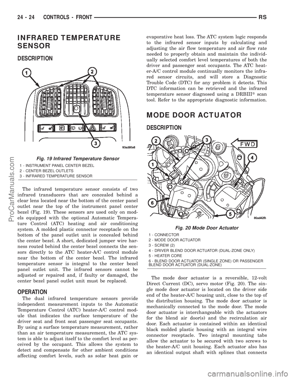
The infrared temperature sensor consists of two
infrared transducers that are concealed behind a
clear lens located near the bottom of the center panel
outlet near the top of the instrument panel center
bezel (Fig. 19). These sensors are used only on mod-
els equipped with the optional Automatic Tempera-
ture Control (ATC) heating and air conditioning
system. A molded plastic connector receptacle on the
bottom of the panel outlet unit is concealed behind
the center bezel. A short, dedicated jumper wire har-
ness routed behind the center bezel connects the sen-
sors directly to the ATC heater-A/C control module
near the bottom of the center bezel. The infrared
temperature sensor is integral to the center bezel
panel outlet unit. The infrared sensors cannot be
adjusted or repaired and, if faulty or damaged, the
center bezel panel outlet unit must be replaced.
OPERATION
The dual infrared temperature sensors provide
independent measurement inputs to the Automatic
Temperature Control (ATC) heater-A/C control mod-
ule that indicates the surface temperature of the
driver seat and front seat passenger seat occupants.
By using a surface temperature measurement, rather
than an air temperature measurement, the ATC sys-
tem is able to adjust itself to the comfort level as per-
ceived by the occupant. This allows the system to
detect and compensate for other ambient conditions
affecting comfort levels, such as solar heat gain orevaporative heat loss. The ATC system logic responds
to the infrared sensor inputs by calculating and
adjusting the air flow temperature and air flow rate
needed to properly obtain and maintain the individ-
ually selected comfort level temperatures of both the
driver and passenger seat occupants. The ATC heat-
er-A/C control module continually monitors the infra-
red sensor circuits, and will store a Diagnostic
Trouble Code (DTC) for any problem it detects. This
DTC information can be retrieved and the infrared
temperature sensor diagnosed using a DRBIIItscan
tool. Refer to the appropriate diagnostic information.
MODE DOOR ACTUATOR
DESCRIPTION
The mode door actuator is a reversible, 12-volt
Direct Current (DC), servo motor (Fig. 20). The sin-
gle mode door actuator is located on the driver side
end of the heater-A/C housing unit, close to the top of
the distribution housing. The mode door actuator is
mechanically connected to the mode door. The mode
door actuator is interchangeable with the actuators
for the blend air door(s) and the recirculation air
door. Each actuator is contained within an identical
black molded plastic housing with an integral wire
connector receptacle. Two integral mounting tabs
allow the actuator to be secured with two screws to
the heater-A/C unit housing. Each actuator also has
an identical output shaft with splines that connects
Fig. 19 Infrared Temperature Sensor
1 - INSTRUMENT PANEL CENTER BEZEL
2 - CENTER BEZEL OUTLETS
3 - INFRARED TEMPERATURE SENSOR
Fig. 20 Mode Door Actuator
1 - CONNECTOR
2 - MODE DOOR ACTUATOR
3 - SCREW (2)
4 - DRIVER BLEND DOOR ACTUATOR (DUAL-ZONE ONLY)
5 - HEATER CORE
6 - BLEND DOOR ACTUATOR (SINGLE ZONE) OR PASSENGER
BLEND DOOR ACTUATOR (DUAL-ZONE)
24 - 24 CONTROLS - FRONTRS
ProCarManuals.com
Page 2279 of 2399
INFRARED TEMPERATURE
SENSOR
DESCRIPTION
The rear infrared temperature sensor consists of
an infrared transducer that is concealed behind the
lens of the rear heater-A/C control in the headliner.
This sensor is used only on models equipped with the
optional Automatic Temperature Control (ATC) heat-
ing and air conditioning system. The rear infrared
temperature sensor is integral to the rear heater-A/C
control. The infrared sensor cannot be adjusted or
repaired and, if faulty or damaged, the rear heater-
A/C control unit must be replaced.
OPERATION
The rear infrared temperature sensor provides an
independent measurement input to the Automatic
Temperature Control (ATC) heater-A/C control mod-
ule that indicates the surface temperature of the rear
seat occupants. By using a surface temperature mea-
surement, rather than an air temperature measure-
ment, the ATC system is able to adjust itself to the
comfort level as perceived by the occupant. This
allows the system to detect and compensate for other
ambient conditions affecting comfort levels, such as
solar heat gain or evaporative heat loss. The ATC
system logic responds to the infrared sensor input by
calculating and adjusting the air flow temperature
and air flow rate needed to properly obtain and
maintain the selected comfort level temperatures for
the rear seat occupants. The ATC heater-A/C control
module continually monitors the infrared sensor cir-
cuit, and will store a Diagnostic Trouble Code (DTC)
for any problem it detects. This DTC information can
be retrieved and the infrared temperature sensor
diagnosed using a DRBIIItscan tool. Refer to the
appropriate diagnostic information.
MODE DOOR ACTUATOR
REMOVAL
(1) Disconnect and isolate the battery negative
cable.
(2) Remove the right quarter trim panel and right
D-pillar trim panel from the quarter inner panel.
(Refer to 23 - BODY/INTERIOR/QUARTER TRIM
PANEL - REMOVAL).
(3) Remove the two screws that secure the top of
the quarter trim panel attaching bracket to the quar-
ter inner panel.
(4) Remove the screw that secures the back of the
rear heater-A/C unit housing to the right D-pillar.(5) Remove the screw that secures the front of the
rear heater-A/C unit housing to the right quarter
inner panel.
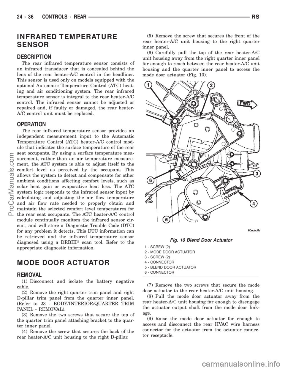
(6) Carefully pull the top of the rear heater-A/C
unit housing away from the right quarter inner panel
far enough to reach between the rear heater-A/C unit
housing and the quarter inner panel to access the
mode door actuator (Fig. 10).
(7) Remove the two screws that secure the mode
door actuator to the rear heater-A/C unit housing.
(8) Pull the mode door actuator away from the
rear heater-A/C unit housing far enough to disengage
the actuator output shaft from the mode door link-
age.
(9) Raise the mode door actuator far enough to
access and disconnect the rear HVAC wire harness
connector for the actuator from the actuator connec-
tor receptacle.
Fig. 10 Blend Door Actuator
1 - SCREW (2)
2 - MODE DOOR ACTUATOR
3 - SCREW (2)
4 - CONNECTOR
5 - BLEND DOOR ACTUATOR
6 - CONNECTOR
24 - 36 CONTROLS - REARRS
ProCarManuals.com