2002 CHRYSLER CARAVAN brake light
[x] Cancel search: brake lightPage 956 of 2399

8W-51 REAR LIGHTING
Component Page
Back-Up Lamp Switch................ 8W-51-5
Battery............................ 8W-51-5
Body Control Module............ 8W-51-2, 3, 4, 5
Brake Lamp Switch................ 8W-51-2, 4
Center High Mounted Stop Lamp........ 8W-51-6
Front Control Module............. 8W-51-2, 4, 5
Fuse 2........................... 8W-51-2, 4
Fuse 3......................... 8W-51-2, 4, 5
Fuse 26.......................... 8W-51-2, 4
G101.............................. 8W-51-5
G103.............................. 8W-51-5Component Page
G302........................ 8W-51-2, 3, 4, 5
G400.............................. 8W-51-6
Integrated Power Module.......... 8W-51-2, 4, 5
Left Rear Lamp Assembly........ 8W-51-2, 3, 4, 5
Left Stop/Turn Signal Relay............ 8W-51-3
License Lamp....................... 8W-51-6
Park Lamp Relay................ 8W-51-2, 4, 5
Right Combination Relay.............. 8W-51-3
Right Rear Lamp Assembly......... 8W-51-2, 4, 5
Trailer Tow Connector................. 8W-51-3
RS8W-51 REAR LIGHTING8W-51-1
ProCarManuals.com
Page 1033 of 2399
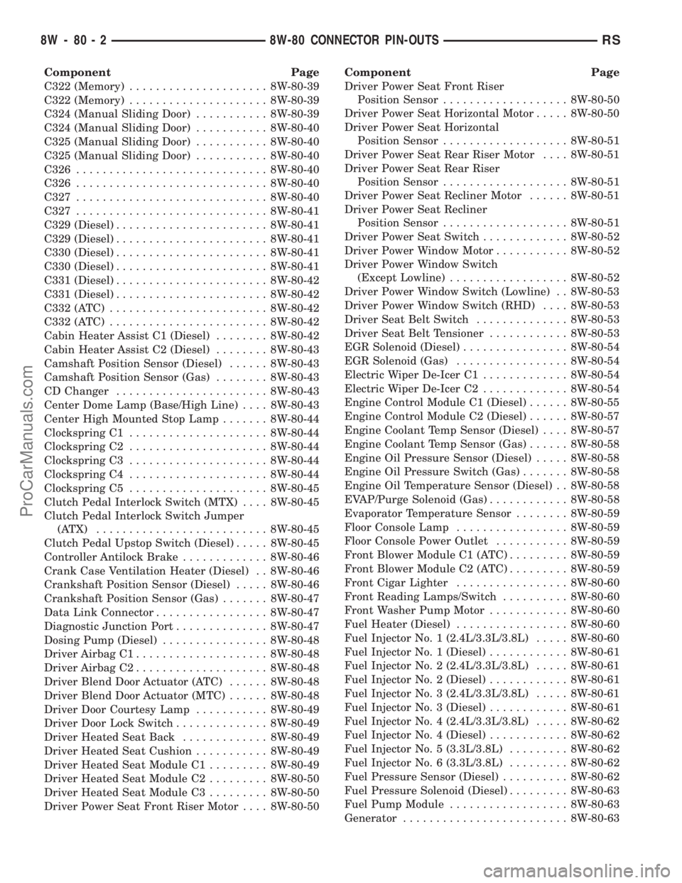
Component Page
C322 (Memory)..................... 8W-80-39
C322 (Memory)..................... 8W-80-39
C324 (Manual Sliding Door)........... 8W-80-39
C324 (Manual Sliding Door)........... 8W-80-40
C325 (Manual Sliding Door)........... 8W-80-40
C325 (Manual Sliding Door)........... 8W-80-40
C326............................. 8W-80-40
C326............................. 8W-80-40
C327............................. 8W-80-40
C327............................. 8W-80-41
C329 (Diesel)....................... 8W-80-41
C329 (Diesel)....................... 8W-80-41
C330 (Diesel)....................... 8W-80-41
C330 (Diesel)....................... 8W-80-41
C331 (Diesel)....................... 8W-80-42
C331 (Diesel)....................... 8W-80-42
C332 (ATC)........................ 8W-80-42
C332 (ATC)........................ 8W-80-42
Cabin Heater Assist C1 (Diesel)........ 8W-80-42
Cabin Heater Assist C2 (Diesel)........ 8W-80-43
Camshaft Position Sensor (Diesel)...... 8W-80-43
Camshaft Position Sensor (Gas)........ 8W-80-43
CD Changer....................... 8W-80-43
Center Dome Lamp (Base/High Line).... 8W-80-43
Center High Mounted Stop Lamp....... 8W-80-44
Clockspring C1..................... 8W-80-44
Clockspring C2..................... 8W-80-44
Clockspring C3..................... 8W-80-44
Clockspring C4..................... 8W-80-44
Clockspring C5..................... 8W-80-45
Clutch Pedal Interlock Switch (MTX).... 8W-80-45
Clutch Pedal Interlock Switch Jumper
(ATX) .......................... 8W-80-45
Clutch Pedal Upstop Switch (Diesel)..... 8W-80-45
Controller Antilock Brake............. 8W-80-46
Crank Case Ventilation Heater (Diesel) . . 8W-80-46
Crankshaft Position Sensor (Diesel)..... 8W-80-46
Crankshaft Position Sensor (Gas)....... 8W-80-47
Data Link Connector................. 8W-80-47
Diagnostic Junction Port.............. 8W-80-47
Dosing Pump (Diesel)................ 8W-80-48
Driver Airbag C1.................... 8W-80-48
Driver Airbag C2.................... 8W-80-48
Driver Blend Door Actuator (ATC)...... 8W-80-48
Driver Blend Door Actuator (MTC)...... 8W-80-48
Driver Door Courtesy Lamp........... 8W-80-49
Driver Door Lock Switch.............. 8W-80-49
Driver Heated Seat Back............. 8W-80-49
Driver Heated Seat Cushion........... 8W-80-49
Driver Heated Seat Module C1......... 8W-80-49
Driver Heated Seat Module C2......... 8W-80-50
Driver Heated Seat Module C3......... 8W-80-50
Driver Power Seat Front Riser Motor.... 8W-80-50Component Page
Driver Power Seat Front Riser
Position Sensor................... 8W-80-50
Driver Power Seat Horizontal Motor..... 8W-80-50
Driver Power Seat Horizontal
Position Sensor................... 8W-80-51
Driver Power Seat Rear Riser Motor.... 8W-80-51
Driver Power Seat Rear Riser
Position Sensor................... 8W-80-51
Driver Power Seat Recliner Motor...... 8W-80-51
Driver Power Seat Recliner
Position Sensor................... 8W-80-51
Driver Power Seat Switch............. 8W-80-52
Driver Power Window Motor........... 8W-80-52
Driver Power Window Switch
(Except Lowline).................. 8W-80-52
Driver Power Window Switch (Lowline) . . 8W-80-53
Driver Power Window Switch (RHD).... 8W-80-53
Driver Seat Belt Switch.............. 8W-80-53
Driver Seat Belt Tensioner............ 8W-80-53
EGR Solenoid (Diesel)................ 8W-80-54
EGR Solenoid (Gas)................. 8W-80-54
Electric Wiper De-Icer C1............. 8W-80-54
Electric Wiper De-Icer C2............. 8W-80-54
Engine Control Module C1 (Diesel)...... 8W-80-55
Engine Control Module C2 (Diesel)...... 8W-80-57
Engine Coolant Temp Sensor (Diesel).... 8W-80-57
Engine Coolant Temp Sensor (Gas)...... 8W-80-58
Engine Oil Pressure Sensor (Diesel)..... 8W-80-58
Engine Oil Pressure Switch (Gas)....... 8W-80-58
Engine Oil Temperature Sensor (Diesel) . . 8W-80-58
EVAP/Purge Solenoid (Gas)............ 8W-80-58
Evaporator Temperature Sensor........ 8W-80-59
Floor Console Lamp................. 8W-80-59
Floor Console Power Outlet........... 8W-80-59
Front Blower Module C1 (ATC)......... 8W-80-59
Front Blower Module C2 (ATC)......... 8W-80-59
Front Cigar Lighter................. 8W-80-60
Front Reading Lamps/Switch.......... 8W-80-60
Front Washer Pump Motor............ 8W-80-60
Fuel Heater (Diesel)................. 8W-80-60
Fuel Injector No. 1 (2.4L/3.3L/3.8L)..... 8W-80-60
Fuel Injector No. 1 (Diesel)............ 8W-80-61
Fuel Injector No. 2 (2.4L/3.3L/3.8L)..... 8W-80-61
Fuel Injector No. 2 (Diesel)............ 8W-80-61
Fuel Injector No. 3 (2.4L/3.3L/3.8L)..... 8W-80-61
Fuel Injector No. 3 (Diesel)............ 8W-80-61
Fuel Injector No. 4 (2.4L/3.3L/3.8L)..... 8W-80-62
Fuel Injector No. 4 (Diesel)............ 8W-80-62
Fuel Injector No. 5 (3.3L/3.8L)......... 8W-80-62
Fuel Injector No. 6 (3.3L/3.8L)......... 8W-80-62
Fuel Pressure Sensor (Diesel).......... 8W-80-62
Fuel Pressure Solenoid (Diesel)......... 8W-80-63
Fuel Pump Module.................. 8W-80-63
Generator......................... 8W-80-63
8W - 80 - 2 8W-80 CONNECTOR PIN-OUTSRS
ProCarManuals.com
Page 1160 of 2399
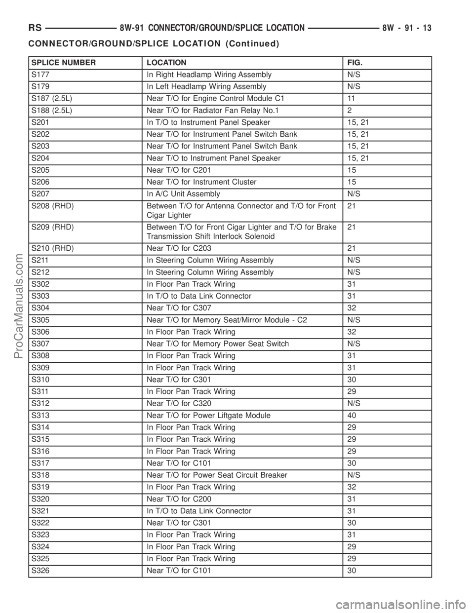
SPLICE NUMBER LOCATION FIG.
S177 In Right Headlamp Wiring Assembly N/S
S179 In Left Headlamp Wiring Assembly N/S
S187 (2.5L) Near T/O for Engine Control Module C1 11
S188 (2.5L) Near T/O for Radiator Fan Relay No.1 2
S201 In T/O to Instrument Panel Speaker 15, 21
S202 Near T/O for Instrument Panel Switch Bank 15, 21
S203 Near T/O for Instrument Panel Switch Bank 15, 21
S204 Near T/O to Instrument Panel Speaker 15, 21
S205 Near T/O for C201 15
S206 Near T/O for Instrument Cluster 15
S207 In A/C Unit Assembly N/S
S208 (RHD) Between T/O for Antenna Connector and T/O for Front
Cigar Lighter21
S209 (RHD) Between T/O for Front Cigar Lighter and T/O for Brake
Transmission Shift Interlock Solenoid21
S210 (RHD) Near T/O for C203 21
S211 In Steering Column Wiring Assembly N/S
S212 In Steering Column Wiring Assembly N/S
S302 In Floor Pan Track Wiring 31
S303 In T/O to Data Link Connector 31
S304 Near T/O for C307 32
S305 Near T/O for Memory Seat/Mirror Module - C2 N/S
S306 In Floor Pan Track Wiring 32
S307 Near T/O for Memory Power Seat Switch N/S
S308 In Floor Pan Track Wiring 31
S309 In Floor Pan Track Wiring 31
S310 Near T/O for C301 30
S311 In Floor Pan Track Wiring 29
S312 Near T/O for C320 N/S
S313 Near T/O for Power Liftgate Module 40
S314 In Floor Pan Track Wiring 29
S315 In Floor Pan Track Wiring 29
S316 In Floor Pan Track Wiring 29
S317 Near T/O for C101 30
S318 Near T/O for Power Seat Circuit Breaker N/S
S319 In Floor Pan Track Wiring 32
S320 Near T/O for C200 31
S321 In T/O to Data Link Connector 31
S322 Near T/O for C301 30
S323 In Floor Pan Track Wiring 31
S324 In Floor Pan Track Wiring 29
S325 In Floor Pan Track Wiring 29
S326 Near T/O for C101 30
RS8W-91 CONNECTOR/GROUND/SPLICE LOCATION8W-91-13
CONNECTOR/GROUND/SPLICE LOCATION (Continued)
ProCarManuals.com
Page 1350 of 2399
INSPECTION
Check manifold for:
²Damage and cracks.
²Mounting surface distortion by using a straight-
edge and thickness gauge.
INSTALLATION - UPPER INTAKE MANIFOLD
(1) If the following components were removed from
manifold, install and tighten to specifications:
CAUTION: The special screws used for the compos-
ite manifold attached components must be installed
slowly using hand tools only. This requirement is to
prevent the melting of material that causes stripped
threads. If threads become stripped, an oversize
repair screw is available. For more information and
procedure (Refer to 9 - ENGINE/MANIFOLDS/IN-
TAKE MANIFOLD - STANDARD PROCEDURE - MAN-
IFOLD STRIPPED THREAD REPAIR).²MAP sensor - 1.7 N´m (15 in. lbs.)
²Throttle cable bracket - 5.6 N´m (50 in. lbs.)
(2) Remove covering on lower intake manifold and
clean surfaces.
(3) Inspect manifold gasket condition. Gaskets can
be re-used, if not damaged. To replace, remove gasket
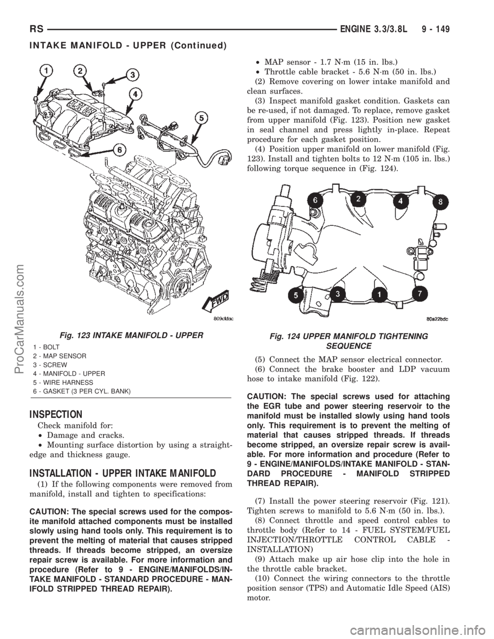
from upper manifold (Fig. 123). Position new gasket
in seal channel and press lightly in-place. Repeat
procedure for each gasket position.
(4) Position upper manifold on lower manifold (Fig.
123). Install and tighten bolts to 12 N´m (105 in. lbs.)
following torque sequence in (Fig. 124).
(5) Connect the MAP sensor electrical connector.
(6) Connect the brake booster and LDP vacuum
hose to intake manifold (Fig. 122).
CAUTION: The special screws used for attaching
the EGR tube and power steering reservoir to the
manifold must be installed slowly using hand tools
only. This requirement is to prevent the melting of
material that causes stripped threads. If threads
become stripped, an oversize repair screw is avail-
able. For more information and procedure (Refer to
9 - ENGINE/MANIFOLDS/INTAKE MANIFOLD - STAN-
DARD PROCEDURE - MANIFOLD STRIPPED
THREAD REPAIR).
(7) Install the power steering reservoir (Fig. 121).
Tighten screws to manifold to 5.6 N´m (50 in. lbs.).
(8) Connect throttle and speed control cables to
throttle body (Refer to 14 - FUEL SYSTEM/FUEL
INJECTION/THROTTLE CONTROL CABLE -
INSTALLATION)
(9) Attach make up air hose clip into the hole in
the throttle cable bracket.
(10) Connect the wiring connectors to the throttle
position sensor (TPS) and Automatic Idle Speed (AIS)
motor.
Fig. 123 INTAKE MANIFOLD - UPPER
1 - BOLT
2 - MAP SENSOR
3 - SCREW
4 - MANIFOLD - UPPER
5 - WIRE HARNESS
6 - GASKET (3 PER CYL. BANK)
Fig. 124 UPPER MANIFOLD TIGHTENING
SEQUENCE
RSENGINE 3.3/3.8L9 - 149
INTAKE MANIFOLD - UPPER (Continued)
ProCarManuals.com
Page 1478 of 2399
FUEL PUMP RELAY
DESCRIPTION
The fuel pump relay is located in the PDC. The
inside top of the PDC cover has a label showing relay
and fuse location.
OPERATION
The fuel pump relay supplies battery voltage to the
fuel pump. A buss bar in the Power Distribution Cen-
ter (PDC) supplies voltage to the solenoid side and
contact side of the relay. The fuel pump relay power
circuit contains a fuse between the buss bar in the
PDC and the relay. The fuse is located in the PDC.
Refer to the Wiring Diagrams for circuit information.
The PCM controls the fuel pump relay by switch-
ing the ground path for the solenoid side of the relay
on and off. The PCM turns the ground path off when
the ignition switch is in the Off position. When the
ignition switch is in the On position, the PCM ener-
gizes the fuel pump. If the crankshaft position sensor
does not detect engine rotation, the PCM de-ener-
gizes the relay after approximately one second.
IDLE AIR CONTROL MOTOR
DESCRIPTION
The idle air control motor is mounted on the throt-
tle body. The PCM operates the idle air control motor
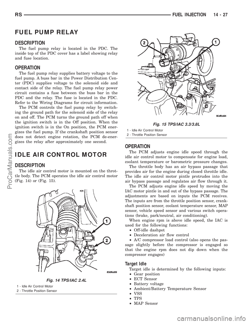
(Fig. 14) or (Fig. 15).
OPERATION
The PCM adjusts engine idle speed through the
idle air control motor to compensate for engine load,
coolant temperature or barometric pressure changes.
The throttle body has an air bypass passage that
provides air for the engine during closed throttle idle.
The idle air control motor pintle protrudes into the
air bypass passage and regulates air flow through it.
The PCM adjusts engine idle speed by moving the
IAC motor pintle in and out of the bypass passage. The
adjustments are based on inputs the PCM receives.
The inputs are from the throttle position sensor, crank-
shaft position sensor, coolant temperature sensor, MAP
sensor, vehicle speed sensor and various switch opera-
tions (brake, park/neutral, air conditioning).
When engine rpm is above idle speed, the IAC is
used for the following functions:
²Off-idle dashpot
²Deceleration air flow control
²A/C compressor load control (also opens the pas-
sage slightly before the compressor is engaged so
that the engine rpm does not dip down when the
compressor engages)
Target Idle
Target idle is determined by the following inputs:
²Gear position
²ECT Sensor
²Battery voltage
²Ambient/Battery Temperature Sensor
²VSS
²TPS
²MAP Sensor
Fig. 14 TPS/IAC 2.4L
1 - Idle Air Control Motor
2 - Throttle Position Sensor
Fig. 15 TPS/IAC 3.3/3.8L
1 - Idle Air Control Motor
2 - Throttle Position Sensor
RSFUEL INJECTION14-27
ProCarManuals.com
Page 1963 of 2399
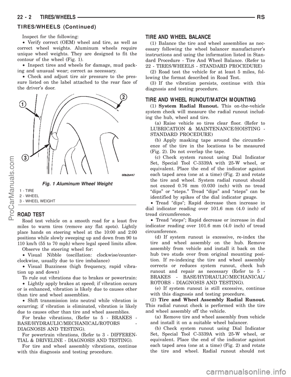
Inspect for the following:
²Verify correct (OEM) wheel and tire, as well as
correct wheel weights. Aluminum wheels require
unique wheel weights. They are designed to fit the
contour of the wheel (Fig. 1).
²Inspect tires and wheels for damage, mud pack-
ing and unusual wear; correct as necessary.
²Check and adjust tire air pressure to the pres-
sure listed on the label attached to the rear face of
the driver's door.
ROAD TEST
Road test vehicle on a smooth road for a least five
miles to warm tires (remove any flat spots). Lightly
place hands on steering wheel at the 10:00 and 2:00
positions while slowly sweeping up and down from 90 to
110 km/h (55 to 70 mph) where legal speed limits allow.
Observe the steering wheel for:
²Visual Nibble (oscillation: clockwise/counter-
clockwise, usually due to tire imbalance)
²Visual Buzziness (high frequency, rapid vibra-
tion up and down)
To rule out vibrations due to brakes or powertrain:
²Lightly apply brakes at speed; if vibration occurs
or is enhanced, vibration is likely due to causes other
than tire and wheel assemblies.
²
Shift transmission into neutral while vibration is
occurring; if vibration is eliminated, vibration is likely
due to causes other than tire and wheel assemblies.
For brake vibrations, (Refer to 5 - BRAKES -
BASE/HYDRAULIC/MECHANICAL/ROTORS -
DIAGNOSIS AND TESTING).
For powertrain vibrations, (Refer to 3 - DIFFEREN-
TIAL & DRIVELINE - DIAGNOSIS AND TESTING).
For tire and wheel assembly vibrations, continue
with this diagnosis and testing procedure.
TIRE AND WHEEL BALANCE
(1) Balance the tire and wheel assemblies as nec-
essary following the wheel balancer manufacturer's
instructions and using the information listed in Stan-
dard Procedure - Tire And Wheel Balance. (Refer to
22 - TIRES/WHEELS - STANDARD PROCEDURE)
(2) Road test the vehicle for at least 5 miles, fol-
lowing the format described in Road Test.
(3) If the vibration persists, continue with this
diagnosis and testing procedure.
TIRE AND WHEEL RUNOUT/MATCH MOUNTING
(1)System Radial Runout.This on-the-vehicle
system check will measure the radial runout includ-
ing the hub, wheel and tire.
(a) Raise vehicle so tires clear floor. (Refer to
LUBRICATION & MAINTENANCE/HOISTING -
STANDARD PROCEDURE)
(b) Apply masking tape around the circumfer-
ence of the tire in the locations to be measured
(Fig. 2). Do not overlap the tape.
(c) Check system runout using Dial Indicator
Set, Special Tool C-3339A with 25-W wheel, or
equivalent. Place the end of the indicator against
each taped area (one at a time) (Fig. 2) and rotate
the tire and wheel. System radial runout should
not exceed 0.76 mm (0.030 inch) with no tread
ªdipsº or ªsteps.º Tread ªdipsº and ªstepsº can be
identified by spikes of the dial indicator gauge.
²Tread9dips9; Rapid decrease then increase in
dial indicator reading over 101.6 mm (4.0 inch) of
tread circumference.
²Tread9steps9; Rapid decrease or increase in dial
indicator reading over 101.6 mm (4.0 inch) of tread
circumference.
(d) If system runout is excessive, re-index the
tire and wheel assembly on the hub. Remove
assembly from vehicle and install it back on the
hub two studs over from original mounting posi-
tion. If re-indexing the tire and wheel assembly
corrects or reduces system runout, check hub
runout and repair as necessary (Refer to 5 -
BRAKES - BASE/HYDRAULIC/MECHANICAL/
ROTORS - DIAGNOSIS AND TESTING).
(e) If system runout is still excessive, continue
with this diagnosis and testing procedure.
(2)Tire and Wheel Assembly Radial Runout.
This radial runout check is performed with the tire
and wheel assembly off the vehicle.
(a) Remove tire and wheel assembly from vehicle
and install it on a suitable wheel balancer.
(b) Check system runout using Dial Indicator
Set, Special Tool C-3339A with 25-W wheel, or
equivalent. Place the end of the indicator against
each taped area (one at a time) (Fig. 2) and rotate
the tire and wheel. Radial runout should not
Fig. 1 Aluminum Wheel Weight
1 - TIRE
2 - WHEEL
3 - WHEEL WEIGHT
22 - 2 TIRES/WHEELSRS
TIRES/WHEELS (Continued)
ProCarManuals.com
Page 1974 of 2399
(6) Retrain tire pressure sensors. (Refer to 22 -
TIRES/WHEELS/TIRE PRESSURE MONITORING/
SENSOR - STANDARD PROCEDURE)
TIRES
DESCRIPTION
DESCRIPTION - TIRE
Tires are designed and engineered for each specific
vehicle. They provide the best overall performance
for normal operation. The ride and handling charac-
teristics match the vehicle's requirements. With
proper care they will give excellent reliability, trac-
tion, skid resistance, and tread life.
Driving habits have more effect on tire life than
any other factor. Careful drivers will obtain, in most
cases, much greater mileage than severe use or care-
less drivers. A few of the driving habits which will
shorten the life of any tire are:
²Rapid acceleration
²Severe application of brakes
²High-speed driving
²Taking turns at excessive speeds
²Striking curbs and other obstacles
²Operating vehicle with over or under inflated
tire pressuresRadial ply tires are more prone to irregular tread
wear. It is important to follow the tire rotation inter-
val shown in the section on Tire Rotation. This will
help to achieve a greater tread-life potential.
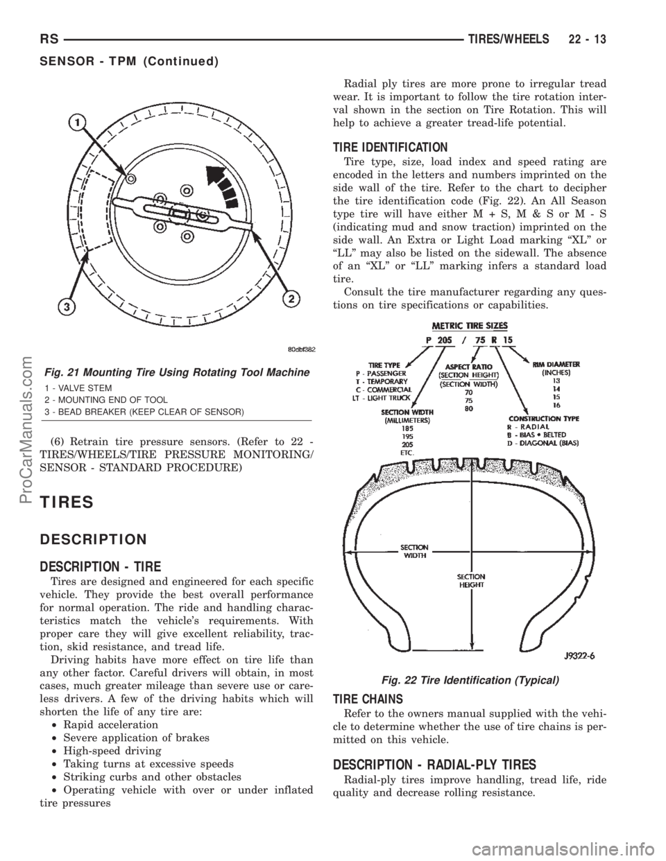
TIRE IDENTIFICATION
Tire type, size, load index and speed rating are
encoded in the letters and numbers imprinted on the
side wall of the tire. Refer to the chart to decipher
the tire identification code (Fig. 22). An All Season
type tire will have eitherM+S,M&SorM-S
(indicating mud and snow traction) imprinted on the
side wall. An Extra or Light Load marking ªXLº or
ªLLº may also be listed on the sidewall. The absence
of an ªXLº or ªLLº marking infers a standard load
tire.
Consult the tire manufacturer regarding any ques-
tions on tire specifications or capabilities.
TIRE CHAINS
Refer to the owners manual supplied with the vehi-
cle to determine whether the use of tire chains is per-
mitted on this vehicle.
DESCRIPTION - RADIAL-PLY TIRES
Radial-ply tires improve handling, tread life, ride
quality and decrease rolling resistance.
Fig. 21 Mounting Tire Using Rotating Tool Machine
1 - VALVE STEM
2 - MOUNTING END OF TOOL
3 - BEAD BREAKER (KEEP CLEAR OF SENSOR)
Fig. 22 Tire Identification (Typical)
RSTIRES/WHEELS22-13
SENSOR - TPM (Continued)
ProCarManuals.com
Page 2318 of 2399
ward far enough to disengage the engine compart-
ment ends of the tubes from the dash panel seal.
(14) Remove the heater core tubes and sealing
plate as a unit from beneath the instrument panel.
(15) Use absorbent toweling to clean up any
engine coolant spills from the preceding operation.
REMOVAL - HEATER CORE
WARNING: REFER TO THE APPLICABLE WARN-
INGS AND CAUTIONS FOR THIS SYSTEM BEFORE
PERFORMING THE FOLLOWING OPERATION.
(Refer to 24 - HEATING & AIR CONDITIONING/
PLUMBING FRONT - WARNING - HEATER PLUMB-
ING).
WARNING: ON VEHICLES EQUIPPED WITH AIR-
BAGS, DISABLE THE AIRBAG SYSTEM BEFORE
ATTEMPTING ANY STEERING WHEEL, STEERING
COLUMN, OR INSTRUMENT PANEL COMPONENT
DIAGNOSIS OR SERVICE. DISCONNECT AND ISO-
LATE THE BATTERY NEGATIVE (GROUND) CABLE,
THEN WAIT TWO MINUTES FOR THE AIRBAG SYS-
TEM CAPACITOR TO DISCHARGE BEFORE PER-
FORMING FURTHER DIAGNOSIS OR SERVICE. THIS
IS THE ONLY SURE WAY TO DISABLE THE AIRBAG
SYSTEM. FAILURE TO TAKE THE PROPER PRE-
CAUTIONS COULD RESULT IN ACCIDENTAL AIR-
BAG DEPLOYMENT AND POSSIBLE PERSONAL
INJURY.
(1) Drain the engine cooling system. (Refer to 7 -
COOLING - STANDARD PROCEDURE - COOLING
SYSTEM DRAIN).
(2) Disconnect and isolate the battery negative
cable.
(3) Remove the silencer boot fasteners located
around the base of the lower steering shaft from the
dash panel so that it may be pushed aside.
(4) Remove the brake lamp switch from its mount-
ing bracket. (Refer to 8 - ELECTRICAL/LAMPS/
LIGHTING - EXTERIOR/BRAKE LAMP SWITCH -
REMOVAL).
(5) Disconnect the power brake booster input rod
(push rod) from the pin on the brake pedal arm.
(Refer to 5 - BRAKES - ABS/HYDRAULIC/ME-
CHANICAL/POWER BRAKE BOOSTER - REMOV-
AL).
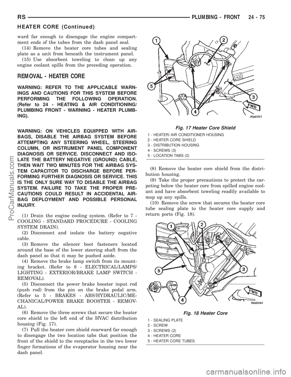
(6) Remove the three screws that secure the heater
core shield to the left end of the HVAC distribution
housing (Fig. 17).
(7) Pull the heater core shield rearward far enough
to disengage the two location tabs that position the
front of the shield to the receptacles in the two lower
finger formations of the evaporator housing near the
dash panel.(8) Remove the heater core shield from the distri-
bution housing.
(9) Take the proper precautions to protect the car-
peting below the heater core from spilled engine cool-
ant and have absorbent toweling readily available to
mop up any spills.
(10) Remove the screw that secures the heater core
tube sealing plate to the heater core supply and
return ports (Fig. 18).
Fig. 17 Heater Core Shield
1 - HEATER/ AIR CONDITIONER HOUSING
2 - HEATER CORE SHIELD
3 - DISTRIBUTION HOUSING
4 - SCREWS (3)
5 - LOCATION TABS (2)
Fig. 18 Heater Core
1 - SEALING PLATE
2 - SCREW
3 - SCREWS (2)
4 - HEATER CORE
5 - HEATER CORE TUBES
RSPLUMBING - FRONT24-75
HEATER CORE (Continued)
ProCarManuals.com