2002 CHRYSLER CARAVAN oil
[x] Cancel search: oilPage 1952 of 2399
ASSEMBLY
NOTE: Do not re-use snap rings when servicing the
intermediate shaft assembly. Discard snap rings
and install new ones provided with available snap
ring service kit.
NOTE: When installing 1/2 & 5/R synchronizers,
make sure to align oil slots on synchronizer hub
face with oil hold in the shaft splined hub journal.
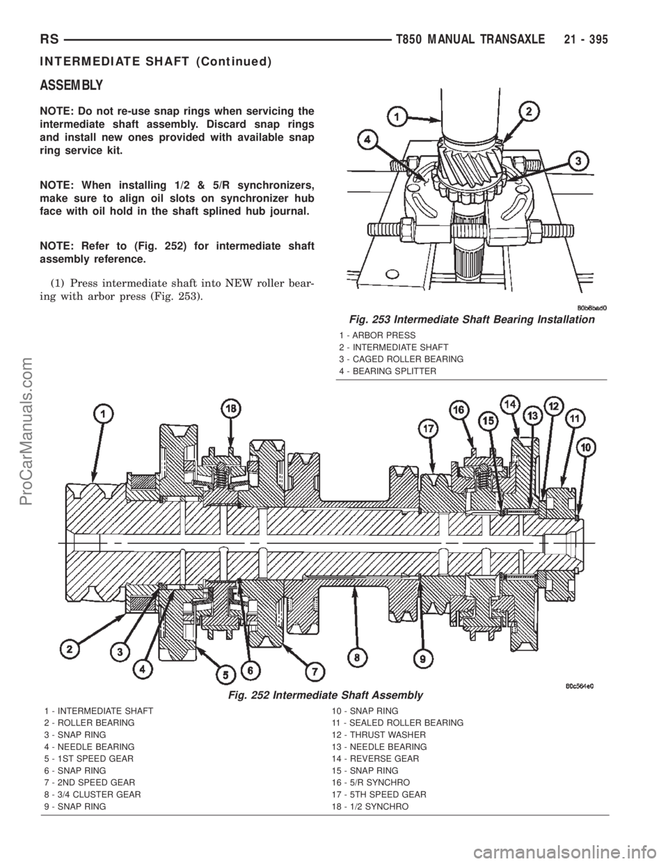
NOTE: Refer to (Fig. 252) for intermediate shaft
assembly reference.
(1) Press intermediate shaft into NEW roller bear-
ing with arbor press (Fig. 253).
Fig. 252 Intermediate Shaft Assembly
1 - INTERMEDIATE SHAFT 10 - SNAP RING
2 - ROLLER BEARING 11 - SEALED ROLLER BEARING
3 - SNAP RING 12 - THRUST WASHER
4 - NEEDLE BEARING 13 - NEEDLE BEARING
5 - 1ST SPEED GEAR 14 - REVERSE GEAR
6 - SNAP RING 15 - SNAP RING
7 - 2ND SPEED GEAR 16 - 5/R SYNCHRO
8 - 3/4 CLUSTER GEAR 17 - 5TH SPEED GEAR
9 - SNAP RING 18 - 1/2 SYNCHRO
Fig. 253 Intermediate Shaft Bearing Installation
1 - ARBOR PRESS
2 - INTERMEDIATE SHAFT
3 - CAGED ROLLER BEARING
4 - BEARING SPLITTER
RST850 MANUAL TRANSAXLE21 - 395
INTERMEDIATE SHAFT (Continued)
ProCarManuals.com
Page 1954 of 2399
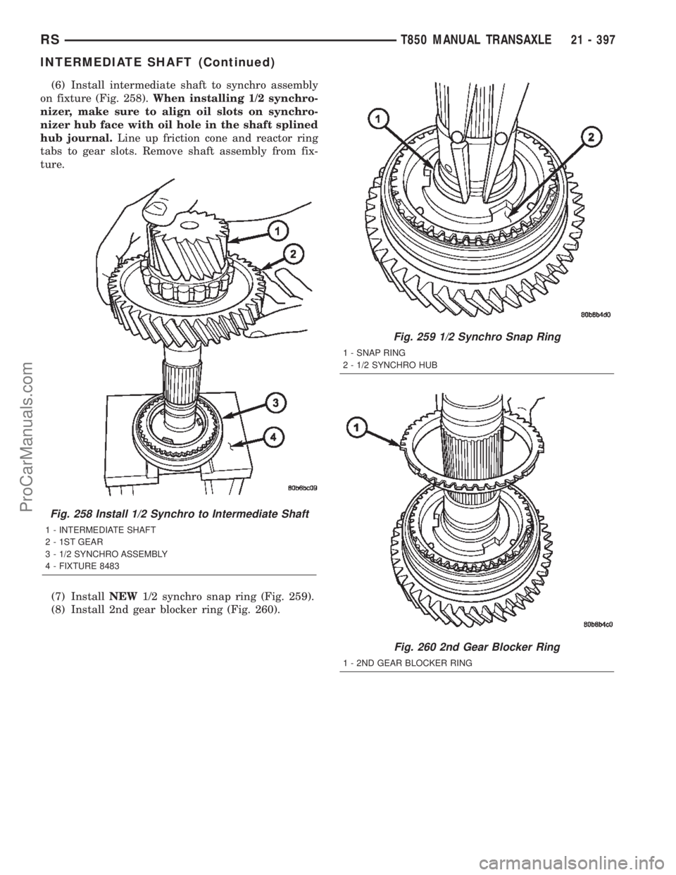
(6) Install intermediate shaft to synchro assembly
on fixture (Fig. 258).When installing 1/2 synchro-
nizer, make sure to align oil slots on synchro-
nizer hub face with oil hole in the shaft splined
hub journal.Line up friction cone and reactor ring
tabs to gear slots. Remove shaft assembly from fix-
ture.
(7) InstallNEW1/2 synchro snap ring (Fig. 259).
(8) Install 2nd gear blocker ring (Fig. 260).
Fig. 258 Install 1/2 Synchro to Intermediate Shaft
1 - INTERMEDIATE SHAFT
2 - 1ST GEAR
3 - 1/2 SYNCHRO ASSEMBLY
4 - FIXTURE 8483
Fig. 259 1/2 Synchro Snap Ring
1 - SNAP RING
2 - 1/2 SYNCHRO HUB
Fig. 260 2nd Gear Blocker Ring
1 - 2ND GEAR BLOCKER RING
RST850 MANUAL TRANSAXLE21 - 397
INTERMEDIATE SHAFT (Continued)
ProCarManuals.com
Page 1956 of 2399
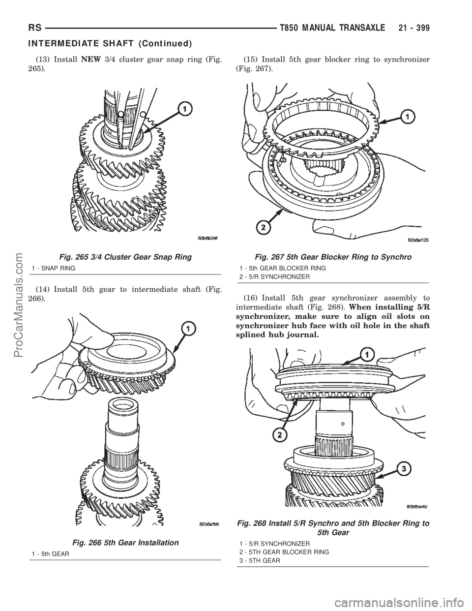
(13) InstallNEW3/4 cluster gear snap ring (Fig.
265).
(14) Install 5th gear to intermediate shaft (Fig.
266).(15) Install 5th gear blocker ring to synchronizer
(Fig. 267).
(16) Install 5th gear synchronizer assembly to
intermediate shaft (Fig. 268).When installing 5/R
synchronizer, make sure to align oil slots on
synchronizer hub face with oil hole in the shaft
splined hub journal.
Fig. 265 3/4 Cluster Gear Snap Ring
1 - SNAP RING
Fig. 266 5th Gear Installation
1 - 5th GEAR
Fig. 267 5th Gear Blocker Ring to Synchro
1 - 5th GEAR BLOCKER RING
2 - 5/R SYNCHRONIZER
Fig. 268 Install 5/R Synchro and 5th Blocker Ring to
5th Gear
1 - 5/R SYNCHRONIZER
2 - 5TH GEAR BLOCKER RING
3 - 5TH GEAR
RST850 MANUAL TRANSAXLE21 - 399
INTERMEDIATE SHAFT (Continued)
ProCarManuals.com
Page 1969 of 2399
(3) Grasp the wheel cover at the edges in line with
the remaining installed wheel mounting nuts and
pull straight outward from the wheel. This will pop
the wheel cover retaining tabs over the two remain-
ing wheel nuts, removing the wheel cover from the
vehicle.
(4) Remove the two remaining wheel mounting
nuts from the hub's studs.
(5) Remove the wheel and tire from the hub.
INSTALLATION
INSTALLATION - TIRE AND WHEEL ASSEMBLY
(ALUMINUM WHEEL)
NOTE: Never use oil or grease on studs or wheel
mounting nuts.
(1) Position the tire and wheel assembly on the
wheel mounting studs using the hub pilot as a guide.
Place and hold the wheel flush up against the mount-
ing surface.
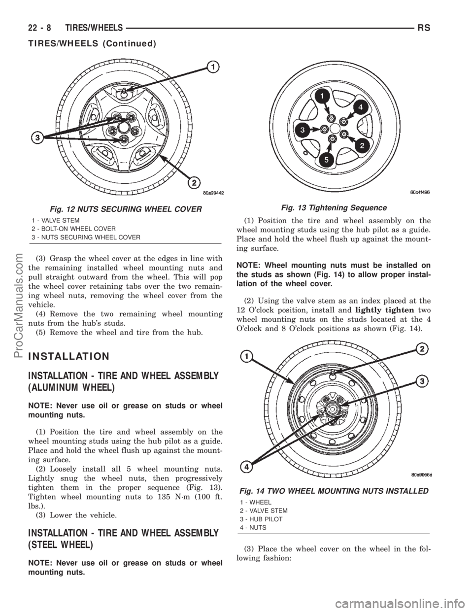
(2) Loosely install all 5 wheel mounting nuts.
Lightly snug the wheel nuts, then progressively
tighten them in the proper sequence (Fig. 13).
Tighten wheel mounting nuts to 135 N´m (100 ft.
lbs.).
(3) Lower the vehicle.
INSTALLATION - TIRE AND WHEEL ASSEMBLY
(STEEL WHEEL)
NOTE: Never use oil or grease on studs or wheel
mounting nuts.(1) Position the tire and wheel assembly on the
wheel mounting studs using the hub pilot as a guide.
Place and hold the wheel flush up against the mount-
ing surface.
NOTE: Wheel mounting nuts must be installed on
the studs as shown (Fig. 14) to allow proper instal-
lation of the wheel cover.
(2) Using the valve stem as an index placed at the
12 O'clock position, install andlightly tightentwo
wheel mounting nuts on the studs located at the 4
O'clock and 8 O'clock positions as shown (Fig. 14).
(3) Place the wheel cover on the wheel in the fol-
lowing fashion:
Fig. 12 NUTS SECURING WHEEL COVER
1 - VALVE STEM
2 - BOLT-ON WHEEL COVER
3 - NUTS SECURING WHEEL COVER
Fig. 13 Tightening Sequence
Fig. 14 TWO WHEEL MOUNTING NUTS INSTALLED
1 - WHEEL
2 - VALVE STEM
3 - HUB PILOT
4 - NUTS
22 - 8 TIRES/WHEELSRS
TIRES/WHEELS (Continued)
ProCarManuals.com
Page 1978 of 2399

Over inflation causes rapid center wear and loss of
the tire's ability to cushion shocks (Fig. 26).
STANDARD PROCEDURE - TIRE PRESSURE
FOR HIGH SPEED OPERATION
DaimlerChrysler Corporation advocates driving at
safe speeds within posted speed limits. Where speed
limits allow the vehicle to be driven at high speeds,
correct tire inflation pressure is very important.
Vehicles loaded to maximum capacity should not be
driven at continuous speeds over 120 km/h (75 mph).
Never exceed the maximum speed capacity of the
tire. For information on tire identification and speed
ratings, (Refer to 22 - TIRES/WHEELS/TIRES -
DESCRIPTION).
STANDARD PROCEDURE - TIRE LEAK
REPAIRING
For proper repairing, a radial tire must be removed
from the wheel. Repairs should only be made if the
defect, or puncture, is in the tread area (Fig. 27). The
tire should be replaced if the puncture is located in
the sidewall.
Deflate tire completely before attempting to dis-
mount the tire from the wheel.Use a lubricant
such as a mild soap solution when dismounting
or mounting tire.Use tools free of burrs or sharp
edges which could damage the tire or wheel rim.
Before mounting tire on wheel, make sure all rust
is removed from the rim bead and repaint if neces-
sary.
Install wheel on vehicle, and progressively tighten
the 5 wheel nuts to a torque of 135 N´m (100 ft. lbs.).
CLEANING - TIRES
Before delivery of a vehicle, remove the protective
coating on the tires with white sidewalls or raisedwhite letters. To remove the protective coating, apply
warm water and let it soak for a few minutes. After-
wards, scrub the coating away with a soft bristle
brush. Steam cleaning may also be used to remove
the coating.
CAUTION: DO NOT use gasoline, mineral oil, oil-
based solvent or a wire brush for cleaning.
WHEELS
DESCRIPTION - WHEEL
Original equipment wheels are designed for proper
operation at all loads up to the specified maximum
vehicle capacity.
All models use either steel or aluminum drop-cen-
ter wheels. Every wheel has raised sections between
the rim flanges and rim drop well called safety
humps (Fig. 28). Initial inflation of the tires forces
the bead over these raised sections. In case of air
loss, the safety humps hold the tire in position on the
wheel until the vehicle can be brought to a safe stop.
Cast aluminum wheels require special balance
weights to fit on the flange of the rim (Fig. 29).
When wheel alignment is necessary on a vehicle
with cast aluminum wheels, special wheel clamps are
required to avoid damage to the wheel's finish.
The wheel studs and nuts are designed for specific
wheel applications and must be replaced with equiv-
alent parts.
Fig. 26 Over Inflation Wear
1 - THIN TIRE TREAD AREAFig. 27 Tire Repair Area
1 - REPAIRABLE AREA
RSTIRES/WHEELS22-17
TIRES (Continued)
ProCarManuals.com
Page 1987 of 2399
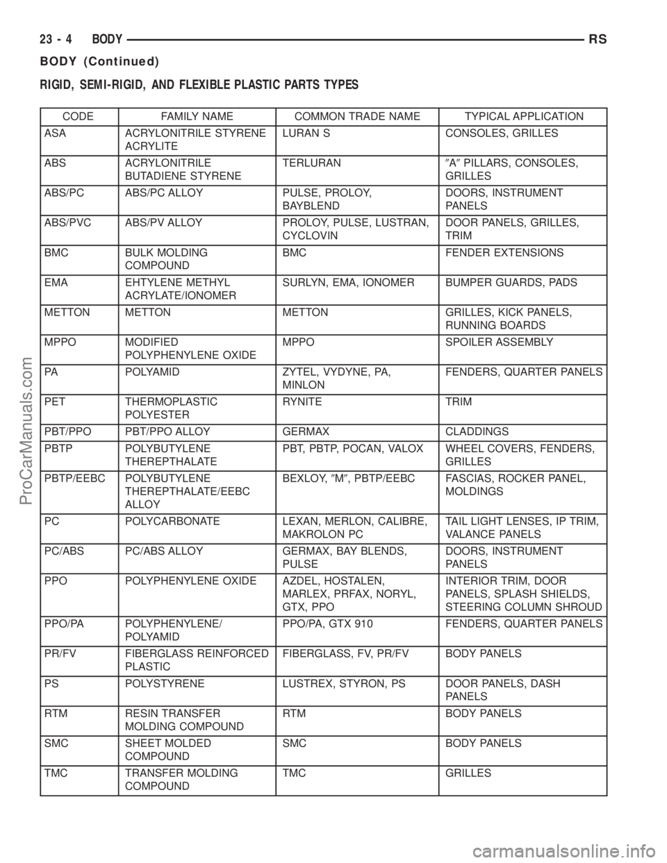
RIGID, SEMI-RIGID, AND FLEXIBLE PLASTIC PARTS TYPES
CODE FAMILY NAME COMMON TRADE NAME TYPICAL APPLICATION
ASA ACRYLONITRILE STYRENE
ACRYLITELURAN S CONSOLES, GRILLES
ABS ACRYLONITRILE
BUTADIENE STYRENETERLURAN9A9PILLARS, CONSOLES,
GRILLES
ABS/PC ABS/PC ALLOY PULSE, PROLOY,
BAYBLENDDOORS, INSTRUMENT
PANELS
ABS/PVC ABS/PV ALLOY PROLOY, PULSE, LUSTRAN,
CYCLOVINDOOR PANELS, GRILLES,
TRIM
BMC BULK MOLDING
COMPOUNDBMC FENDER EXTENSIONS
EMA EHTYLENE METHYL
ACRYLATE/IONOMERSURLYN, EMA, IONOMER BUMPER GUARDS, PADS
METTON METTON METTON GRILLES, KICK PANELS,
RUNNING BOARDS
MPPO MODIFIED
POLYPHENYLENE OXIDEMPPO SPOILER ASSEMBLY
PA POLYAMID ZYTEL, VYDYNE, PA,
MINLONFENDERS, QUARTER PANELS
PET THERMOPLASTIC
POLYESTERRYNITE TRIM
PBT/PPO PBT/PPO ALLOY GERMAX CLADDINGS
PBTP POLYBUTYLENE
THEREPTHALATEPBT, PBTP, POCAN, VALOX WHEEL COVERS, FENDERS,
GRILLES
PBTP/EEBC POLYBUTYLENE
THEREPTHALATE/EEBC
ALLOYBEXLOY,9M9, PBTP/EEBC FASCIAS, ROCKER PANEL,
MOLDINGS
PC POLYCARBONATE LEXAN, MERLON, CALIBRE,
MAKROLON PCTAIL LIGHT LENSES, IP TRIM,
VALANCE PANELS
PC/ABS PC/ABS ALLOY GERMAX, BAY BLENDS,
PULSEDOORS, INSTRUMENT
PANELS
PPO POLYPHENYLENE OXIDE AZDEL, HOSTALEN,
MARLEX, PRFAX, NORYL,
GTX, PPOINTERIOR TRIM, DOOR
PANELS, SPLASH SHIELDS,
STEERING COLUMN SHROUD
PPO/PA POLYPHENYLENE/
POLYAMIDPPO/PA, GTX 910 FENDERS, QUARTER PANELS
PR/FV FIBERGLASS REINFORCED
PLASTICFIBERGLASS, FV, PR/FV BODY PANELS
PS POLYSTYRENE LUSTREX, STYRON, PS DOOR PANELS, DASH
PANELS
RTM RESIN TRANSFER
MOLDING COMPOUNDRTM BODY PANELS
SMC SHEET MOLDED
COMPOUNDSMC BODY PANELS
TMC TRANSFER MOLDING
COMPOUNDTMC GRILLES
23 - 4 BODYRS
BODY (Continued)
ProCarManuals.com
Page 1988 of 2399
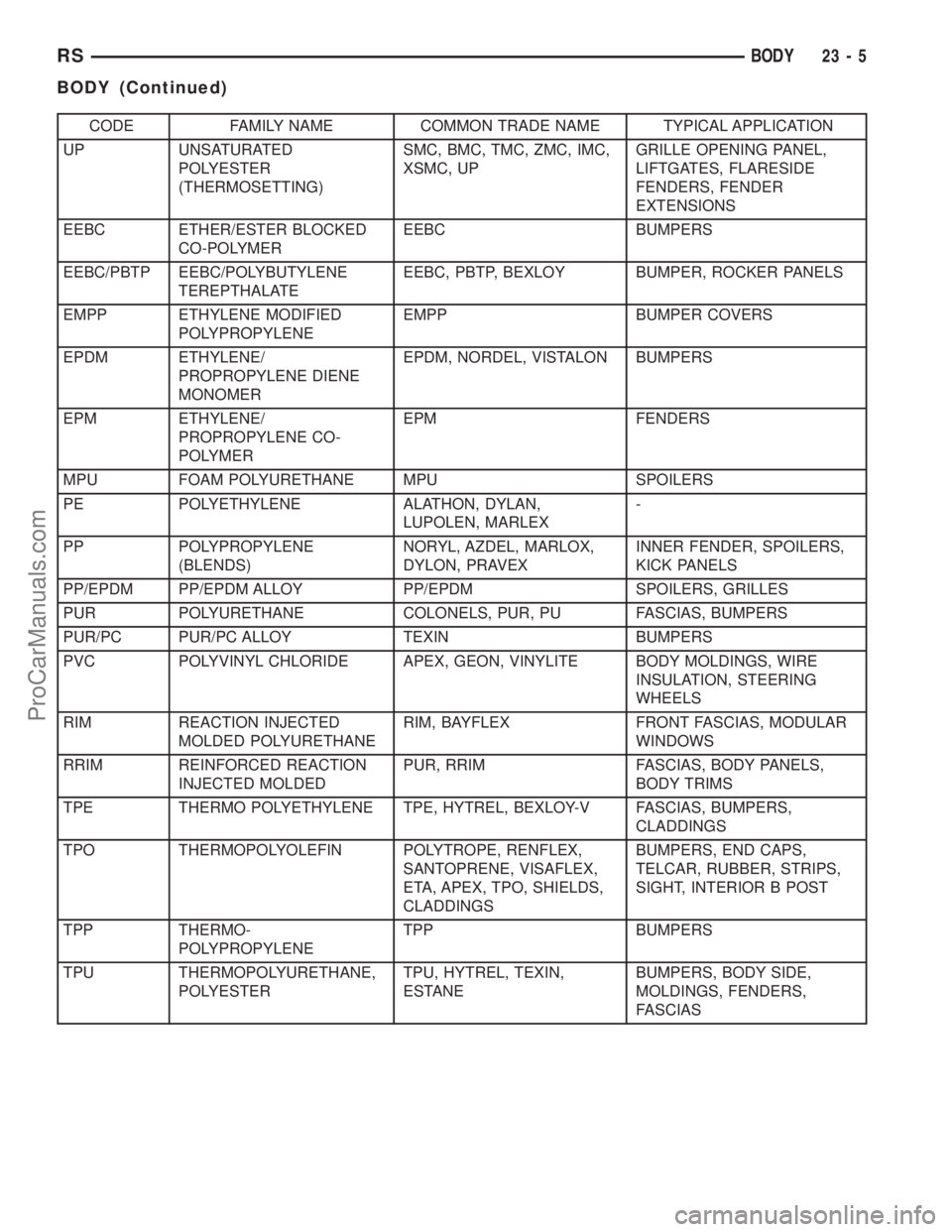
CODE FAMILY NAME COMMON TRADE NAME TYPICAL APPLICATION
UP UNSATURATED
POLYESTER
(THERMOSETTING)SMC, BMC, TMC, ZMC, IMC,
XSMC, UPGRILLE OPENING PANEL,
LIFTGATES, FLARESIDE
FENDERS, FENDER
EXTENSIONS
EEBC ETHER/ESTER BLOCKED
CO-POLYMEREEBC BUMPERS
EEBC/PBTP EEBC/POLYBUTYLENE
TEREPTHALATEEEBC, PBTP, BEXLOY BUMPER, ROCKER PANELS
EMPP ETHYLENE MODIFIED
POLYPROPYLENEEMPP BUMPER COVERS
EPDM ETHYLENE/
PROPROPYLENE DIENE
MONOMEREPDM, NORDEL, VISTALON BUMPERS
EPM ETHYLENE/
PROPROPYLENE CO-
POLYMEREPM FENDERS
MPU FOAM POLYURETHANE MPU SPOILERS
PE POLYETHYLENE ALATHON, DYLAN,
LUPOLEN, MARLEX-
PP POLYPROPYLENE
(BLENDS)NORYL, AZDEL, MARLOX,
DYLON, PRAVEXINNER FENDER, SPOILERS,
KICK PANELS
PP/EPDM PP/EPDM ALLOY PP/EPDM SPOILERS, GRILLES
PUR POLYURETHANE COLONELS, PUR, PU FASCIAS, BUMPERS
PUR/PC PUR/PC ALLOY TEXIN BUMPERS
PVC POLYVINYL CHLORIDE APEX, GEON, VINYLITE BODY MOLDINGS, WIRE
INSULATION, STEERING
WHEELS
RIM REACTION INJECTED
MOLDED POLYURETHANERIM, BAYFLEX FRONT FASCIAS, MODULAR
WINDOWS
RRIM REINFORCED REACTION
INJECTED MOLDEDPUR, RRIM FASCIAS, BODY PANELS,
BODY TRIMS
TPE THERMO POLYETHYLENE TPE, HYTREL, BEXLOY-V FASCIAS, BUMPERS,
CLADDINGS
TPO THERMOPOLYOLEFIN POLYTROPE, RENFLEX,
SANTOPRENE, VISAFLEX,
ETA, APEX, TPO, SHIELDS,
CLADDINGSBUMPERS, END CAPS,
TELCAR, RUBBER, STRIPS,
SIGHT, INTERIOR B POST
TPP THERMO-
POLYPROPYLENETPP BUMPERS
TPU THERMOPOLYURETHANE,
POLYESTERTPU, HYTREL, TEXIN,
ESTANEBUMPERS, BODY SIDE,
MOLDINGS, FENDERS,
FASCIAS
RSBODY23-5
BODY (Continued)
ProCarManuals.com
Page 1990 of 2399
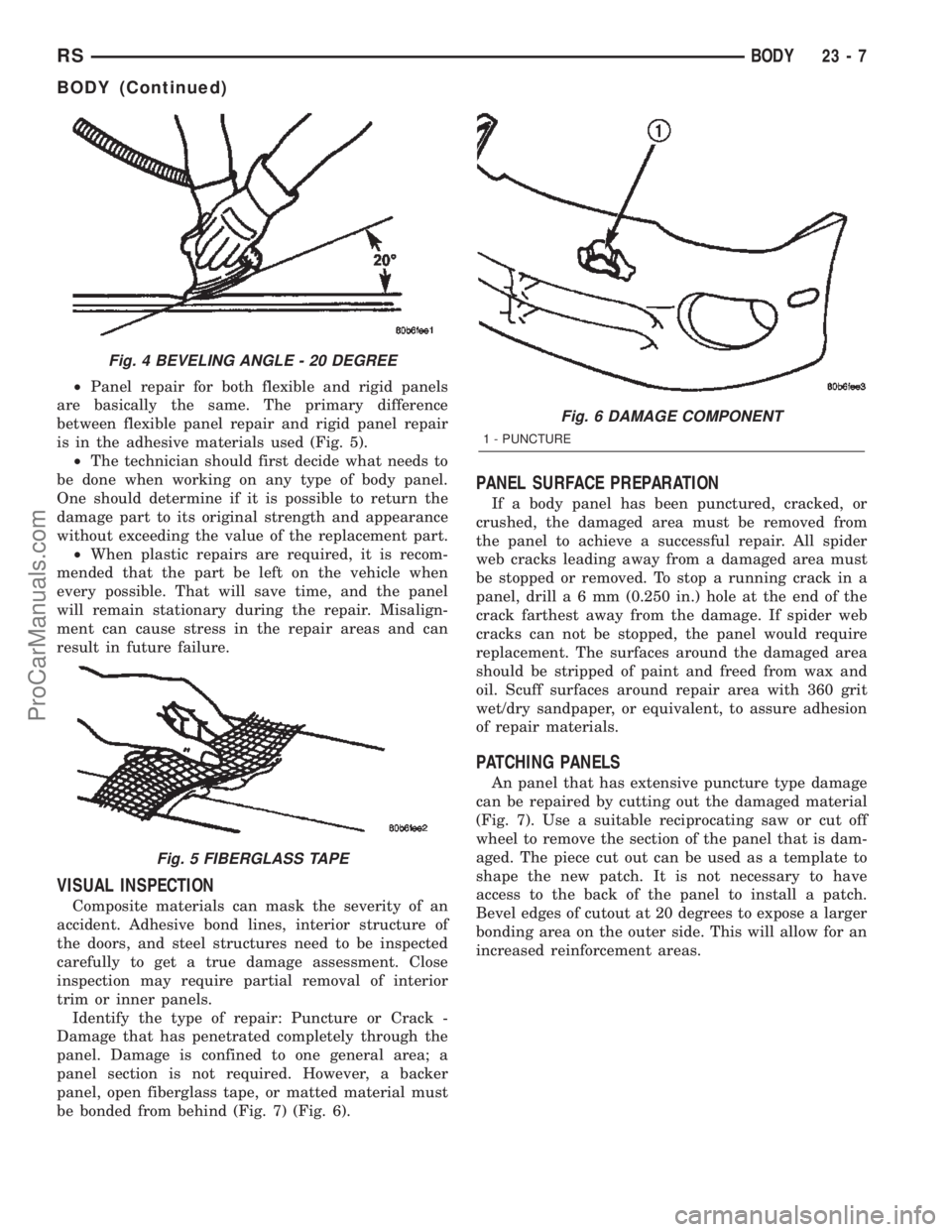
²Panel repair for both flexible and rigid panels
are basically the same. The primary difference
between flexible panel repair and rigid panel repair
is in the adhesive materials used (Fig. 5).
²The technician should first decide what needs to
be done when working on any type of body panel.
One should determine if it is possible to return the
damage part to its original strength and appearance
without exceeding the value of the replacement part.
²When plastic repairs are required, it is recom-
mended that the part be left on the vehicle when
every possible. That will save time, and the panel
will remain stationary during the repair. Misalign-
ment can cause stress in the repair areas and can
result in future failure.
VISUAL INSPECTION
Composite materials can mask the severity of an
accident. Adhesive bond lines, interior structure of
the doors, and steel structures need to be inspected
carefully to get a true damage assessment. Close
inspection may require partial removal of interior
trim or inner panels.
Identify the type of repair: Puncture or Crack -
Damage that has penetrated completely through the
panel. Damage is confined to one general area; a
panel section is not required. However, a backer
panel, open fiberglass tape, or matted material must
be bonded from behind (Fig. 7) (Fig. 6).
PANEL SURFACE PREPARATION
If a body panel has been punctured, cracked, or
crushed, the damaged area must be removed from
the panel to achieve a successful repair. All spider
web cracks leading away from a damaged area must
be stopped or removed. To stop a running crack in a
panel, drilla6mm(0.250 in.) hole at the end of the
crack farthest away from the damage. If spider web
cracks can not be stopped, the panel would require
replacement. The surfaces around the damaged area
should be stripped of paint and freed from wax and
oil. Scuff surfaces around repair area with 360 grit
wet/dry sandpaper, or equivalent, to assure adhesion
of repair materials.
PATCHING PANELS
An panel that has extensive puncture type damage
can be repaired by cutting out the damaged material
(Fig. 7). Use a suitable reciprocating saw or cut off
wheel to remove the section of the panel that is dam-
aged. The piece cut out can be used as a template to
shape the new patch. It is not necessary to have
access to the back of the panel to install a patch.
Bevel edges of cutout at 20 degrees to expose a larger
bonding area on the outer side. This will allow for an
increased reinforcement areas.
Fig. 4 BEVELING ANGLE - 20 DEGREE
Fig. 5 FIBERGLASS TAPE
Fig. 6 DAMAGE COMPONENT
1 - PUNCTURE
RSBODY23-7
BODY (Continued)
ProCarManuals.com