Page 1853 of 2399
REMOVAL
NOTE: If valve body is replaced or reconditioned,
the TCM Quick Learn Procedure must be per-
formed. (Refer to 8 - ELECTRICAL/ELECTRONIC
CONTROL MODULES/TRANSMISSION CONTROL
MODULE - STANDARD PROCEDURE)
(1) Disconnect battery negative cable.
(2) Disconnect gearshift cable from manual valve
lever.
(3) Remove manual valve lever from manual shaft.
(4) Raise vehicle on hoist.
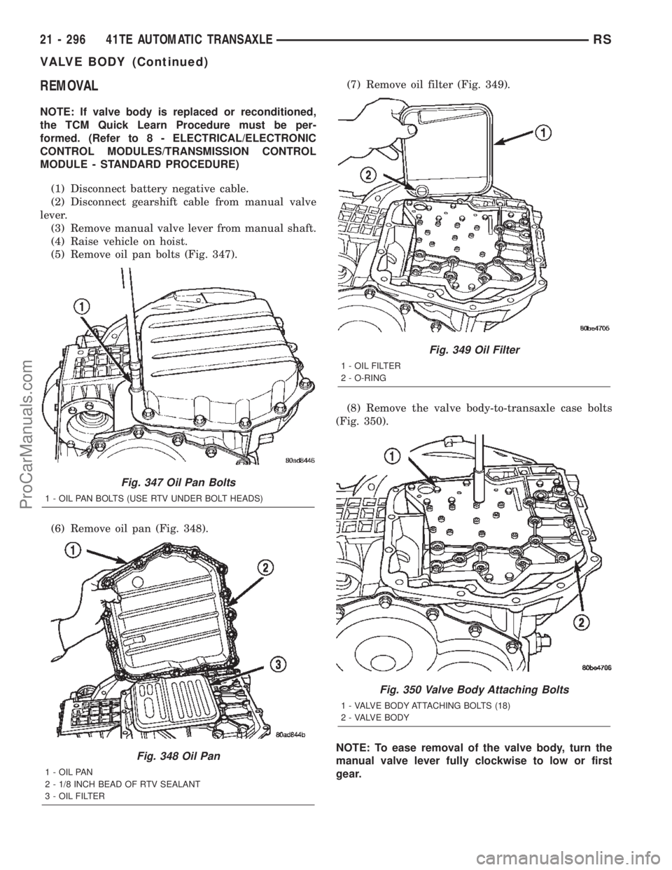
(5) Remove oil pan bolts (Fig. 347).
(6) Remove oil pan (Fig. 348).(7) Remove oil filter (Fig. 349).
(8) Remove the valve body-to-transaxle case bolts
(Fig. 350).
NOTE: To ease removal of the valve body, turn the
manual valve lever fully clockwise to low or first
gear.
Fig. 347 Oil Pan Bolts
1 - OIL PAN BOLTS (USE RTV UNDER BOLT HEADS)
Fig. 348 Oil Pan
1 - OIL PAN
2 - 1/8 INCH BEAD OF RTV SEALANT
3 - OIL FILTER
Fig. 349 Oil Filter
1 - OIL FILTER
2 - O-RING
Fig. 350 Valve Body Attaching Bolts
1 - VALVE BODY ATTACHING BOLTS (18)
2 - VALVE BODY
21 - 296 41TE AUTOMATIC TRANSAXLERS
VALVE BODY (Continued)
ProCarManuals.com
Page 1856 of 2399
(7) Invert assembly and remove Transfer Plate
(Fig. 359). Beware of loose check balls.
(8) Remove oil screen (Fig. 360).(9) Remove the overdrive clutch (#5) check valve
(Fig. 361)
(10) Remove separator plate (Fig. 362).
Fig. 359 Remove Transfer Plate
1 - TRANSFER PLATE
Fig. 360 Remove Oil Screen
1 - OIL SCREEN
Fig. 361 Remove Overdrive Clutch (#5) Check Valve
1 - OVERDRIVE CLUTCH (#5) CHECK VALVE
Fig. 362 Remove Separator Plate
1 - SEPARATOR PLATE
2 - VALVE BODY
RS41TE AUTOMATIC TRANSAXLE21 - 299
VALVE BODY (Continued)
ProCarManuals.com
Page 1861 of 2399
(6) Install thermal valve into transfer plate (Fig.
373).
(7) Install separator plate to valve body (Fig. 374).(8) Install the overdrive clutch (#5) check valve to
separator plate (Fig. 375)
(9) Install oil screen to separator plate (Fig. 376).
Fig. 373 Install Thermal Valve
1 - THERMAL VALVE
Fig. 374 Install Separator Plate
1 - SEPARATOR PLATE
2 - VALVE BODY
Fig. 375 Install Overdrive Clutch (#5) Check Valve
1 - OVERDRIVE CLUTCH (#5) CHECK VALVE
Fig. 376 Install Oil Screen
1 - OIL SCREEN
21 - 304 41TE AUTOMATIC TRANSAXLERS
VALVE BODY (Continued)
ProCarManuals.com
Page 1862 of 2399
(10) Install transfer plate to valve body and sepa-
rator plate. Make sure oil screen and #5 check valve
do not bind (Fig. 377).
(11) Install twenty-four transfer plate to valve
body screws (Fig. 378) and torque to 5 N´m (45 in.
lbs.).(12) Install 2/4 Accumulator components as shown
in (Fig. 379).
(13) Torque 2/4 Accumulator retainer to 5 N´m (45
in. lbs.) (Fig. 380).
Fig. 377 Install Transfer Plate
1 - TRANSFER PLATE
Fig. 378 Install Valve Body to Transfer Plate Screws
1 - SCREW (24)
2 - TRANSFER PLATE
3 - VALVE BODY
Fig. 379 2/4 Accumulator Assembly
1 - VALVE BODY
2 - RETAINER PLATE
3 - DETENT SPRING
4 - SPRINGS
5 - SEALS
6 - PISTON
Fig. 380 2/4 Accumulator Retaining Plate
1 - 2±4 ACCUMULATOR RETAINING PLATE
2 - DETENT SPRING
RS41TE AUTOMATIC TRANSAXLE21 - 305
VALVE BODY (Continued)
ProCarManuals.com
Page 1864 of 2399
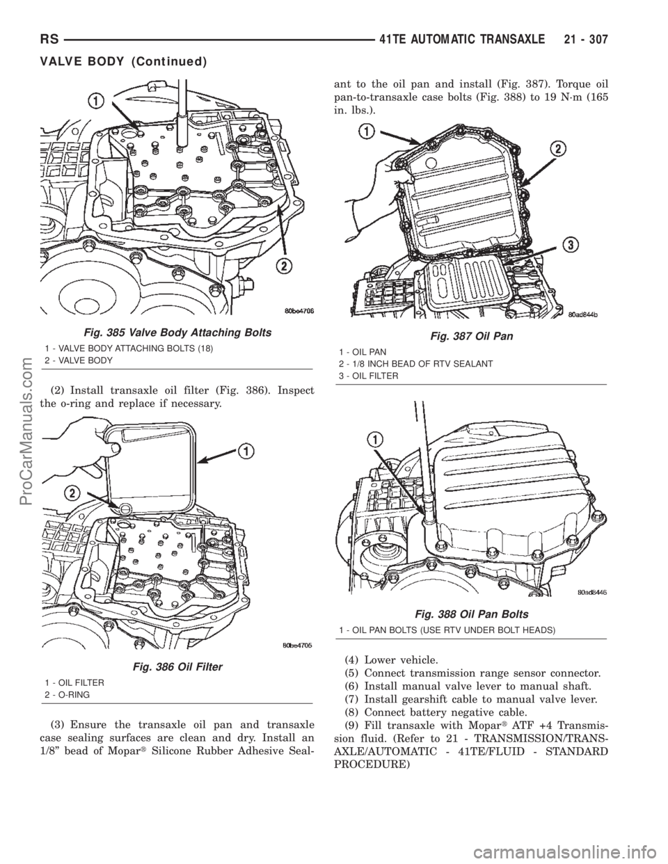
(2) Install transaxle oil filter (Fig. 386). Inspect
the o-ring and replace if necessary.
(3) Ensure the transaxle oil pan and transaxle
case sealing surfaces are clean and dry. Install an
1/8º bead of MopartSilicone Rubber Adhesive Seal-ant to the oil pan and install (Fig. 387). Torque oil
pan-to-transaxle case bolts (Fig. 388) to 19 N´m (165
in. lbs.).
(4) Lower vehicle.
(5) Connect transmission range sensor connector.
(6) Install manual valve lever to manual shaft.
(7) Install gearshift cable to manual valve lever.
(8) Connect battery negative cable.
(9) Fill transaxle with MopartATF +4 Transmis-
sion fluid. (Refer to 21 - TRANSMISSION/TRANS-
AXLE/AUTOMATIC - 41TE/FLUID - STANDARD
PROCEDURE)
Fig. 385 Valve Body Attaching Bolts
1 - VALVE BODY ATTACHING BOLTS (18)
2 - VALVE BODY
Fig. 386 Oil Filter
1 - OIL FILTER
2 - O-RING
Fig. 387 Oil Pan
1 - OIL PAN
2 - 1/8 INCH BEAD OF RTV SEALANT
3 - OIL FILTER
Fig. 388 Oil Pan Bolts
1 - OIL PAN BOLTS (USE RTV UNDER BOLT HEADS)
RS41TE AUTOMATIC TRANSAXLE21 - 307
VALVE BODY (Continued)
ProCarManuals.com
Page 1875 of 2399
DIAGNOSIS AND TESTING - COMMON
PROBLEM CAUSES
The majority of transaxle malfunctions are a result
of:
²Insufficient lubrication
²Incorrect lubricant
²Misassembled or damaged internal components
²Improper operation
HARD SHIFTING
Hard shifting may be caused by a misadjusted
crossover cable. If hard shifting is accompanied by
gear clash, synchronizer clutch and stop rings or gear
teeth may be worn or damaged.
Hard shifting may also be caused by a binding or
broken shift cover mechanism. Remove shift cover
and verify smooth operation. Replace as necessary.
Misassembled synchronizer components also cause
shifting problems. Incorrectly installed synchronizer
sleeves, keys, balls, or springs can cause shift prob-
lems.
NOISY OPERATION
Transaxle noise is most often a result of worn or
damaged components. Chipped, broken gear or syn-
chronizer teeth, and brinnelled, spalled bearings all
cause noise.
Abnormal wear and damage to the internal compo-
nents is frequently the end result of insufficient
lubricant.
SLIPS OUT OF GEAR
Transaxle disengagement may be caused by mis-
aligned or damaged shift components, or worn teeth
on the drive gears or synchronizer components. Incor-
rect assembly also causes gear disengagement. Check
for missing snap rings.
LOW LUBRICANT LEVEL
Insufficient transaxle lubricant is usually the
result of leaks, or inaccurate fluid level check or refill
method. Leakage is evident by the presence of oil
around the leak point. If leakage is not evident, the
condition is probably the result of an underfill.
If air±powered lubrication equipment is used to fill
a transaxle, be sure the equipment is properly cali-
brated. Equipment out of calibration can lead to an
underfill condition.
CLUTCH PROBLEMS
Worn, damaged, or misaligned clutch components
can cause difficult shifting, gear clash, and noise.
A worn or damaged clutch disc, pressure plate, or
release bearing can cause hard shifting and gear
clash.
REMOVAL
REMOVAL - 2.4L GAS
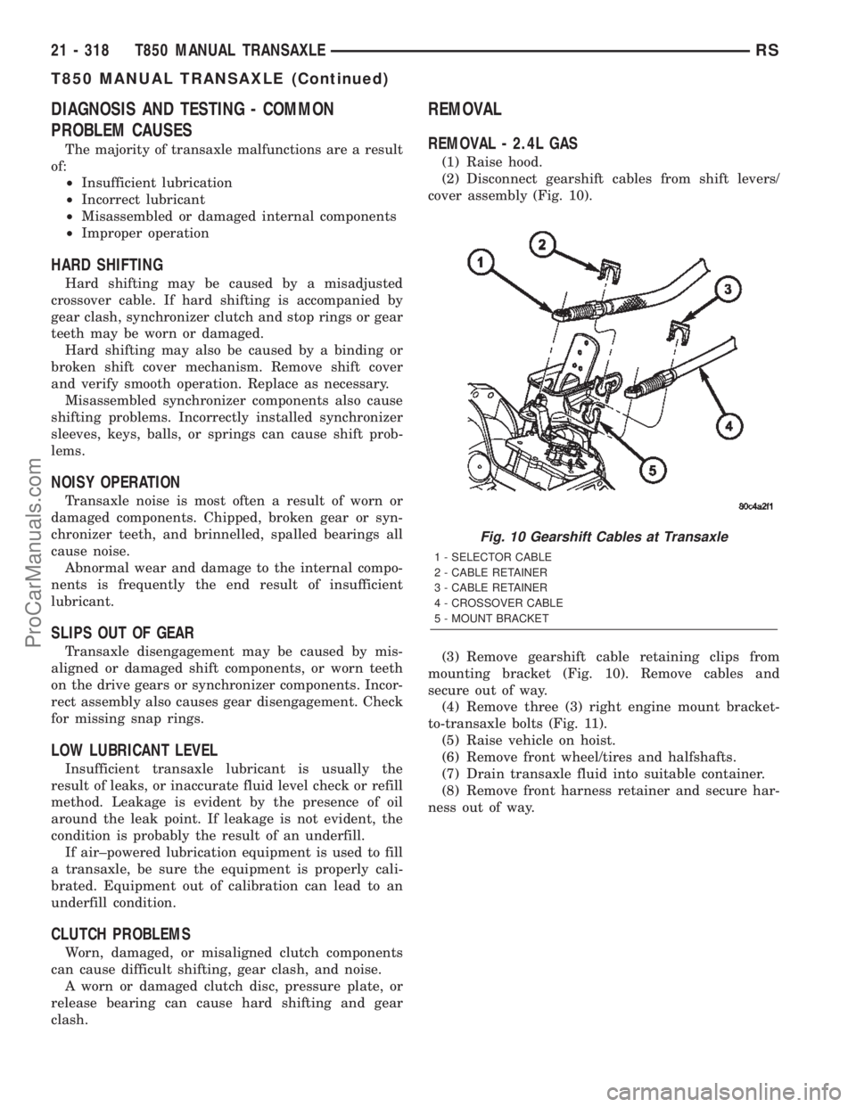
(1) Raise hood.
(2) Disconnect gearshift cables from shift levers/
cover assembly (Fig. 10).
(3) Remove gearshift cable retaining clips from
mounting bracket (Fig. 10). Remove cables and
secure out of way.
(4) Remove three (3) right engine mount bracket-
to-transaxle bolts (Fig. 11).
(5) Raise vehicle on hoist.
(6) Remove front wheel/tires and halfshafts.
(7) Drain transaxle fluid into suitable container.
(8) Remove front harness retainer and secure har-
ness out of way.
Fig. 10 Gearshift Cables at Transaxle
1 - SELECTOR CABLE
2 - CABLE RETAINER
3 - CABLE RETAINER
4 - CROSSOVER CABLE
5 - MOUNT BRACKET
21 - 318 T850 MANUAL TRANSAXLERS
T850 MANUAL TRANSAXLE (Continued)
ProCarManuals.com
Page 1876 of 2399
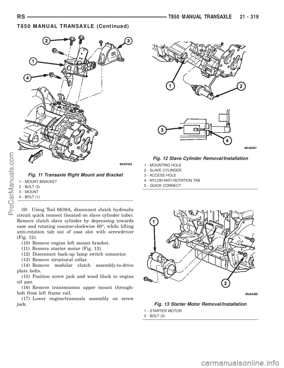
(9) Using Tool 6638A, disconnect clutch hydraulic
circuit quick connect (located on slave cylinder tube).
Remove clutch slave cylinder by depressing towards
case and rotating counter-clockwise 60É, while lifting
anti-rotation tab out of case slot with screwdriver
(Fig. 12).
(10) Remove engine left mount bracket.
(11) Remove starter motor (Fig. 13).
(12) Disconnect back-up lamp switch connector.
(13) Remove structural collar.
(14) Remove modular clutch assembly-to-drive
plate bolts.
(15) Position screw jack and wood block to engine
oil pan.
(16) Remove transmission upper mount through-
bolt from left frame rail.
(17) Lower engine/transaxle assembly on screw
jack.
Fig. 11 Transaxle Right Mount and Bracket
1 - MOUNT BRACKET
2 - BOLT (3)
3 - MOUNT
4 - BOLT (1)
Fig. 12 Slave Cylinder Removal/Installation
1 - MOUNTING HOLE
2 - SLAVE CYLINDER
3 - ACCESS HOLE
4 - NYLON ANTI-ROTATION TAB
5 - QUICK CONNECT
Fig. 13 Starter Motor Removal/Installation
1 - STARTER MOTOR
2 - BOLT (3)
RST850 MANUAL TRANSAXLE21 - 319
T850 MANUAL TRANSAXLE (Continued)
ProCarManuals.com
Page 1879 of 2399
(11) Raise vehicle on hoist.
(12) Remove front wheel/tires and halfshafts.
(13) Remove underbody splash shield.
(14) Drain transaxle fluid into suitable container.
(15) Remove front harness retainer and secure
harness out of way.
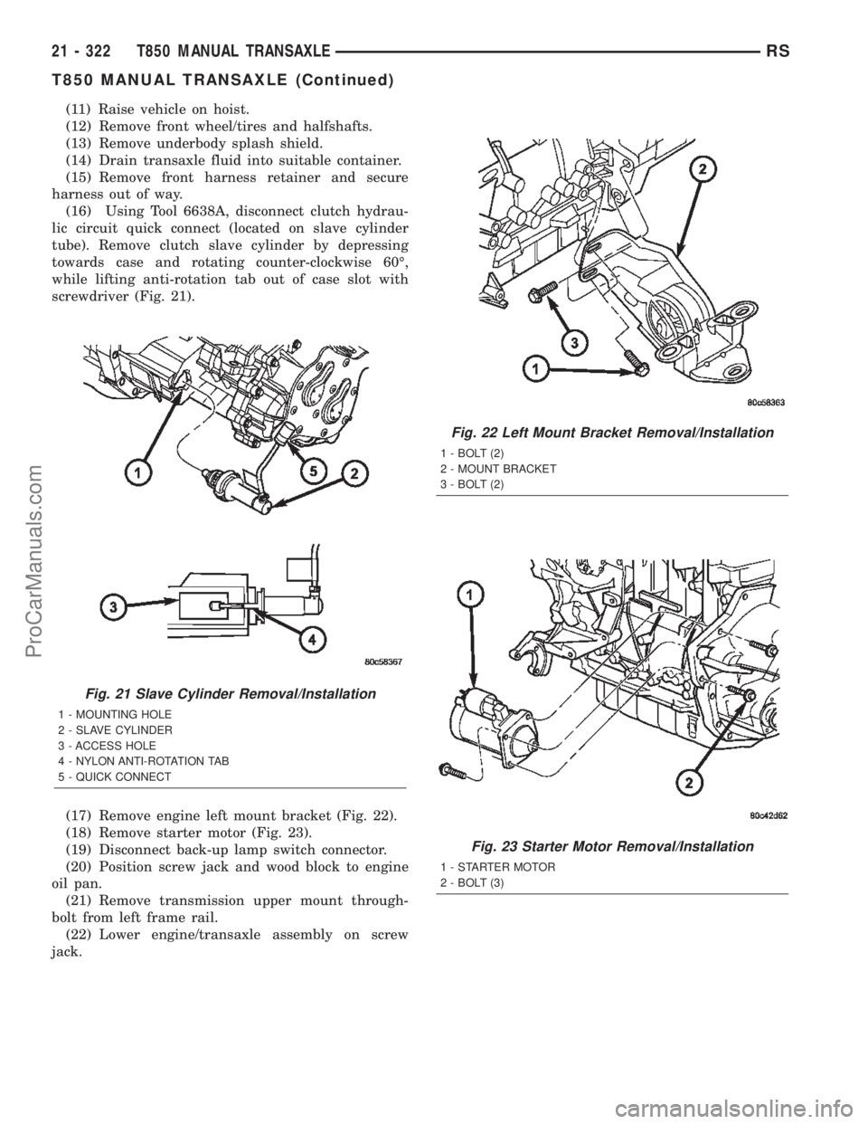
(16) Using Tool 6638A, disconnect clutch hydrau-
lic circuit quick connect (located on slave cylinder
tube). Remove clutch slave cylinder by depressing
towards case and rotating counter-clockwise 60É,
while lifting anti-rotation tab out of case slot with
screwdriver (Fig. 21).
(17) Remove engine left mount bracket (Fig. 22).
(18) Remove starter motor (Fig. 23).
(19) Disconnect back-up lamp switch connector.
(20) Position screw jack and wood block to engine
oil pan.
(21) Remove transmission upper mount through-
bolt from left frame rail.
(22) Lower engine/transaxle assembly on screw
jack.
Fig. 21 Slave Cylinder Removal/Installation
1 - MOUNTING HOLE
2 - SLAVE CYLINDER
3 - ACCESS HOLE
4 - NYLON ANTI-ROTATION TAB
5 - QUICK CONNECT
Fig. 22 Left Mount Bracket Removal/Installation
1 - BOLT (2)
2 - MOUNT BRACKET
3 - BOLT (2)
Fig. 23 Starter Motor Removal/Installation
1 - STARTER MOTOR
2 - BOLT (3)
21 - 322 T850 MANUAL TRANSAXLERS
T850 MANUAL TRANSAXLE (Continued)
ProCarManuals.com