2002 CHRYSLER CARAVAN AUX
[x] Cancel search: AUXPage 14 of 2399

LUBRICATION & MAINTENANCE
TABLE OF CONTENTS
page page
LUBRICATION & MAINTENANCE
SPECIFICATIONS - FLUID CAPACITIES.......1
INTERNATIONAL SYMBOLS
DESCRIPTION..........................2
FLUID TYPES
DESCRIPTION
DESCRIPTION - ENGINE OIL AND
LUBRICANTS.........................2
DESCRIPTION - ENGINE COOLANT........3
DESCRIPTION - FLEXIBLE FUEL ENGINE
OIL .................................3
DESCRIPTION - AUTOMATIC
TRANSMISSION FLUID..................4
DESCRIPTION - FUEL REQUIREMENTS.....4
DESCRIPTION - FUEL REQUIREMENTS -
DIESEL ENGINE.......................6DESCRIPTION - ENGINE OIL - DIESEL
ENGINES............................6
FLUID FILL/CHECK LOCATIONS
DESCRIPTION..........................6
LUBRICATION POINTS
DESCRIPTION..........................6
MAINTENANCE SCHEDULES
DESCRIPTION..........................6
HOISTING
STANDARD PROCEDURE - HOISTING........6
JUMP STARTING
STANDARD PROCEDURE - JUMP STARTING . . 7
TOWING
STANDARD PROCEDURE - TOWING.........8
LUBRICATION &
MAINTENANCE
SPECIFICATIONS - FLUID CAPACITIES
DESCRIPTION SPECIFICATION
Fuel Tank (Gas) 75 L (20 gal.)
Fuel Tank (Diesel) 75 L (20 gal.)
Engine Oil* - 2.4 L 4.7 L (5.0 qts.)
Engine Oil* - 3.3/3.8 L 4.0 L (4.5 qts.)
Engine Oil* - 2.5 L
(Diesel)6.0 L (6.3 qts.)
Cooling System** - 2.4 L 10.7 L (11.4 qts.)
Cooling System** - 2.5 L
Turbo Diesel with
Auxiliary Heater13.8 L (14.6 qts.)
Cooling System** -
3.3/3.8 L without Auxiliary
Heater12.6 L (13.4 qts.)
DESCRIPTION SPECIFICATION
Cooling System** -
3.3/3.8 L with Auxiliary
Heater15.4 L (16.3 qts.)
Automatic Transaxle -
Service Fill3.8 L (4.0 qts.)
Automatic Transaxle -
31TH Overhaul Fill8.6 L (9.1 qts.)
Automatic Transaxle -
41TE Overhaul Fill9.2 L (9.7 qts.)
Manual Transaxle (T850
5-Speed)2.4-2.7 L (2.5-2.9 qts.)
AWD Power Transfer Unit 1.15 L (2.4 pts.)
Power Steering 1.2 L (2.5 pts.)
AWD Bi-directional
Overrunning Clutch0.575 L (1.22 pts.)
AWD Rear Carrier 0.7 L (1.48 pts.)
* (includes oil filter)
** (includes heater and recovery/reserve bottle)
RSLUBRICATION & MAINTENANCE0-1
ProCarManuals.com
Page 297 of 2399

SPECIFICATIONS
SPECIFICATIONS - TORQUE
2.5L DIESEL - TORQUE SPECIFICATIONS
DESCRIPTION N´m Ft. Lbs. In. Lbs.
Water Pump Housing Nuts 24.4 18 215
Thermostat Housing Bolts 27.5 21 Ð
Accessory Drive Belt
Tensioner Bolt47.1 35 Ð
Accessory Drive Belt Idler
Bolt53 39 Ð
SPECIFICATIONS - COOLING SYSTEM
CAPACITY
SPECIFICATIONS
DESCRIPTION SPECIFICATION
Cooling System With
Auxiliary Heater16.6 Liters (17.5 qts.)
Cooling System With Out
Auxiliary Heater13.8 Liters (14.6 qts.)
7a - 8 COOLING 2.5L TURBO DIESELRG
COOLING 2.5L TURBO DIESEL (Continued)
ProCarManuals.com
Page 359 of 2399

(M) Check Engine Lamp (MIL) will illuminate during engine operation if this Diagnostic Trouble Code was recorded.
(G) Generator Lamp Illuminated
GENERIC
SCAN TOOL
CODEDRB SCAN TOOL DISPLAY DESCRIPTION OF DIAGNOSTIC TROUBLE CODE
P1298 Lean Operation at Wide Open Throttle A prolonged lean condition is detected during Wide Open
Throttle.
P1299 (M) Vacuum Leak Found (IAC Fully
Seated)MAP Sensor signal does not correlate to Throttle Position
Sensor signal. Possible vacuum leak.
P1388 Auto Shutdown Relay Control Circuit An open or shorted condition detected in the ASD or CNG
shutoff relay control ckt.
P1389 No ASD Relay Output Voltage At PCM No Z1 or Z2 voltage sensed when the auto shutdown relay is
energized.
P1390 (M) Timing Belt Skipped 1 Tooth or More Relationship between Cam and Crank signals not correct.
P1391 (M) Intermittent Loss of CMP or CKP Loss of the Cam Position Sensor or Crank Position sensor
has occurred. For PL 2.0L
P1398 (M) Mis-Fire Adaptive Numerator at Limit PCM is unable to learn the Crank Sensor's signal in
preparation for Misfire Diagnostics. Probable defective Crank
Sensor.
P1399 Wait To Start Lamp Circuit An open or shorted condition detected in the Wait to Start
Lamp circuit.
P1403 No 5 Volts to EGR Sensor Loss of 5v feed to the EGR position sensor.
P1476 Too Little Secondary Air Insufficient flow of secondary air injection detected during
aspirator test.(was P0411)
P1477 Too Much Secondary Air Excessive flow of secondary air injection detected during
aspirator test (was P0411).
P1478 (M) Battery Temp Sensor Volts Out of Limit Internal temperature sensor input voltage out of an
acceptable range.
P1479 Transmission Fan Relay Circuit An open or shorted condition detected in the transmission
fan relay circuit.
P1480 PCV Solenoid Circuit An open or shorted condition detected in the PCV solenoid
circuit.
P1481 EATX RPM Pulse Performance ETAX RPM pulse generator signal for misfire detection does
not correlate with expected value.
P1482 Catalyst Temperature Sensor Circuit
Shorted LowCatalyst temperature sensor circuit shorted low.
P1483 Catalyst Temperature Sensor Circuit
Shorted High.Catalyst temperature sensor circuit shorted high.
P1484 Catalytic Converter Overheat Detected A catalyst overheat condition has been detected by the
catalyst temperature sensor.
P1485 Air Injection Solenoid Circuit An open or shorted condition detected in the air assist
solenoid circuit.
P1486 (M) Evap Leak Monitor Pinched Hose
FoundLDP has detected a pinched hose in the evaporative hose
system.
P1487 Hi Speed Rad Fan CTRL Relay Circuit An open or shorted condition detected in the control circuit of
the #2 high speed radiator fan control relay.
P1488 Auxiliary 5 Volt Supply Output Too Low Auxiliary 5 volt sensor feed is sensed to be below an
acceptable limit.
8E - 22 ELECTRONIC CONTROL MODULESRS
POWERTRAIN CONTROL MODULE (Continued)
ProCarManuals.com
Page 1363 of 2399
INSTALLATION
INSTALLATION.......................47
INSTALLATION.......................48
OIL PRESSURE SENSOR/SWITCH
DESCRIPTION.........................48
REMOVAL.............................48
INSTALLATION.........................48
OIL TEMPERATURE SENSOR
DESCRIPTION.........................48
REMOVAL.............................48
INSTALLATION.........................48
OIL PRESSURE RELIEF VALVE
DESCRIPTION.........................49
REMOVAL.............................49
INSTALLATION.........................49
OIL COOLER & LINES
REMOVAL.............................50
INSTALLATION.........................50
OIL FILTER
DESCRIPTION.........................51
REMOVAL.............................51
INSTALLATION.........................51
OIL JET
DESCRIPTION.........................52
REMOVAL.............................52
INSTALLATION.........................52
INTAKE MANIFOLD
DESCRIPTION.........................52
REMOVAL.............................52INSTALLATION.........................52
VALVE TIMING
STANDARD PROCEDURE - LOCKING ENGINE
90É AFTER TDC.......................53
BALANCE SHAFT
DESCRIPTION.........................54
OPERATION...........................54
REMOVAL.............................55
INSTALLATION.........................55
TIMING BELT / CHAIN COVER(S)
REMOVAL
REMOVAL - TIMING BELT OUTER COVER . . 56
REMOVAL - TIMING BELT INNER COVER . . . 56
INSTALLATION
INSTALLATION - TIMING BELT OUTER
COVER.............................56
INSTALLATION - TIMING BELT INNER
COVER.............................57
TIMING BELT IDLER PULLEY
REMOVAL.............................58
INSTALLATION.........................58
TMNG BELT/CHAIN TENSIONER
REMOVAL.............................59
INSTALLATION.........................59
ADJUSTMENTS
ADJUSTMENT - TIMING BELT TENSIONER . 60
TIMING BELT/CHAIN AND SPROCKETS
REMOVAL.............................60
INSTALLATION.........................61
ENGINE 2.5L TURBO DIESEL
DESCRIPTION
DESCRIPTION - 2.5L COMMON RAIL DIESEL
ENGINE
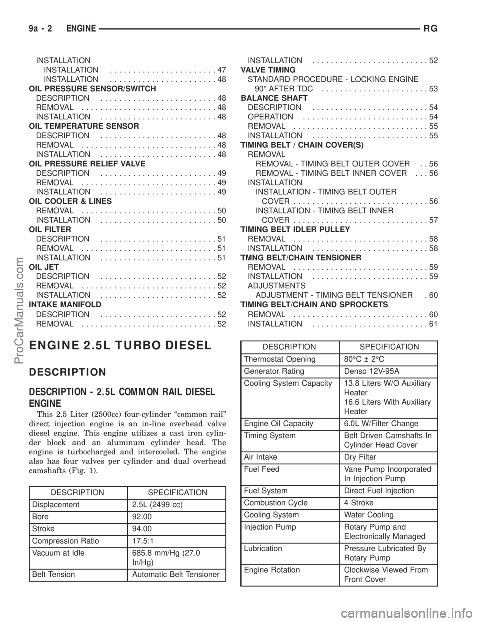
This 2.5 Liter (2500cc) four-cylinder ªcommon railº
direct injection engine is an in-line overhead valve
diesel engine. This engine utilizes a cast iron cylin-
der block and an aluminum cylinder head. The
engine is turbocharged and intercooled. The engine
also has four valves per cylinder and dual overhead
camshafts (Fig. 1).
DESCRIPTION SPECIFICATION
Displacement 2.5L (2499 cc)
Bore 92.00
Stroke 94.00
Compression Ratio 17.5:1
Vacuum at Idle 685.8 mm/Hg (27.0
In/Hg)
Belt Tension Automatic Belt Tensioner
DESCRIPTION SPECIFICATION
Thermostat Opening 80ÉC 2ÉC
Generator Rating Denso 12V-95A
Cooling System Capacity 13.8 Liters W/O Auxiliary
Heater
16.6 Liters With Auxiliary
Heater
Engine Oil Capacity 6.0L W/Filter Change
Timing System Belt Driven Camshafts In
Cylinder Head Cover
Air Intake Dry Filter
Fuel Feed Vane Pump Incorporated
In Injection Pump
Fuel System Direct Fuel Injection
Combustion Cycle 4 Stroke
Cooling System Water Cooling
Injection Pump Rotary Pump and
Electronically Managed
Lubrication Pressure Lubricated By
Rotary Pump
Engine Rotation Clockwise Viewed From
Front Cover
9a - 2 ENGINERG
ProCarManuals.com
Page 1459 of 2399
FUEL PUMP MODULE
DESCRIPTION
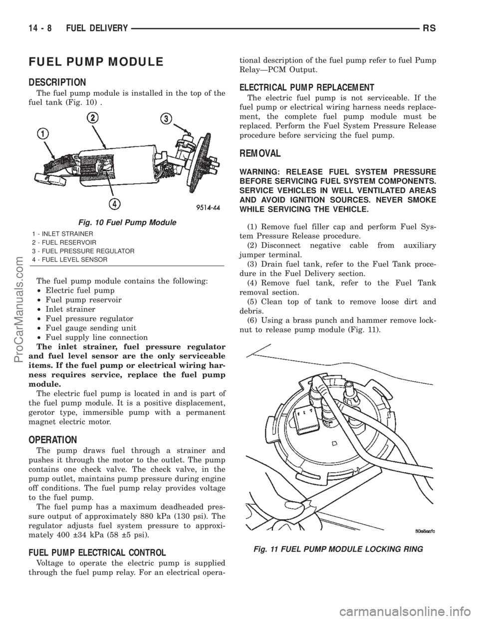
The fuel pump module is installed in the top of the
fuel tank (Fig. 10) .
The fuel pump module contains the following:
²Electric fuel pump
²Fuel pump reservoir
²Inlet strainer
²Fuel pressure regulator
²Fuel gauge sending unit
²Fuel supply line connection
The inlet strainer, fuel pressure regulator
and fuel level sensor are the only serviceable
items. If the fuel pump or electrical wiring har-
ness requires service, replace the fuel pump
module.
The electric fuel pump is located in and is part of
the fuel pump module. It is a positive displacement,
gerotor type, immersible pump with a permanent
magnet electric motor.
OPERATION
The pump draws fuel through a strainer and
pushes it through the motor to the outlet. The pump
contains one check valve. The check valve, in the
pump outlet, maintains pump pressure during engine
off conditions. The fuel pump relay provides voltage
to the fuel pump.
The fuel pump has a maximum deadheaded pres-
sure output of approximately 880 kPa (130 psi). The
regulator adjusts fuel system pressure to approxi-
mately 400 34 kPa (58 5 psi).
FUEL PUMP ELECTRICAL CONTROL
Voltage to operate the electric pump is supplied
through the fuel pump relay. For an electrical opera-tional description of the fuel pump refer to fuel Pump
RelayÐPCM Output.
ELECTRICAL PUMP REPLACEMENT
The electric fuel pump is not serviceable. If the
fuel pump or electrical wiring harness needs replace-
ment, the complete fuel pump module must be
replaced. Perform the Fuel System Pressure Release
procedure before servicing the fuel pump.
REMOVAL
WARNING: RELEASE FUEL SYSTEM PRESSURE
BEFORE SERVICING FUEL SYSTEM COMPONENTS.
SERVICE VEHICLES IN WELL VENTILATED AREAS
AND AVOID IGNITION SOURCES. NEVER SMOKE
WHILE SERVICING THE VEHICLE.
(1) Remove fuel filler cap and perform Fuel Sys-
tem Pressure Release procedure.
(2) Disconnect negative cable from auxiliary
jumper terminal.
(3) Drain fuel tank, refer to the Fuel Tank proce-
dure in the Fuel Delivery section.
(4) Remove fuel tank, refer to the Fuel Tank
removal section.
(5) Clean top of tank to remove loose dirt and
debris.
(6) Using a brass punch and hammer remove lock-
nut to release pump module (Fig. 11).
Fig. 10 Fuel Pump Module
1 - INLET STRAINER
2 - FUEL RESERVOIR
3 - FUEL PRESSURE REGULATOR
4 - FUEL LEVEL SENSOR
Fig. 11 FUEL PUMP MODULE LOCKING RING
14 - 8 FUEL DELIVERYRS
ProCarManuals.com
Page 1464 of 2399
(4) Install the 3 screws at the filler door.
(5) Install the canister from filler tube (Fig. 21).
(6) Install the splash shield.
(7) Install the left rear tire.
(8) lower vehicle.
(9) Connect the negative battery cable.
INLET FILTER
REMOVAL
(1) Remove fuel pump module. Refer to Fuel Pump
Module Removal in this section.
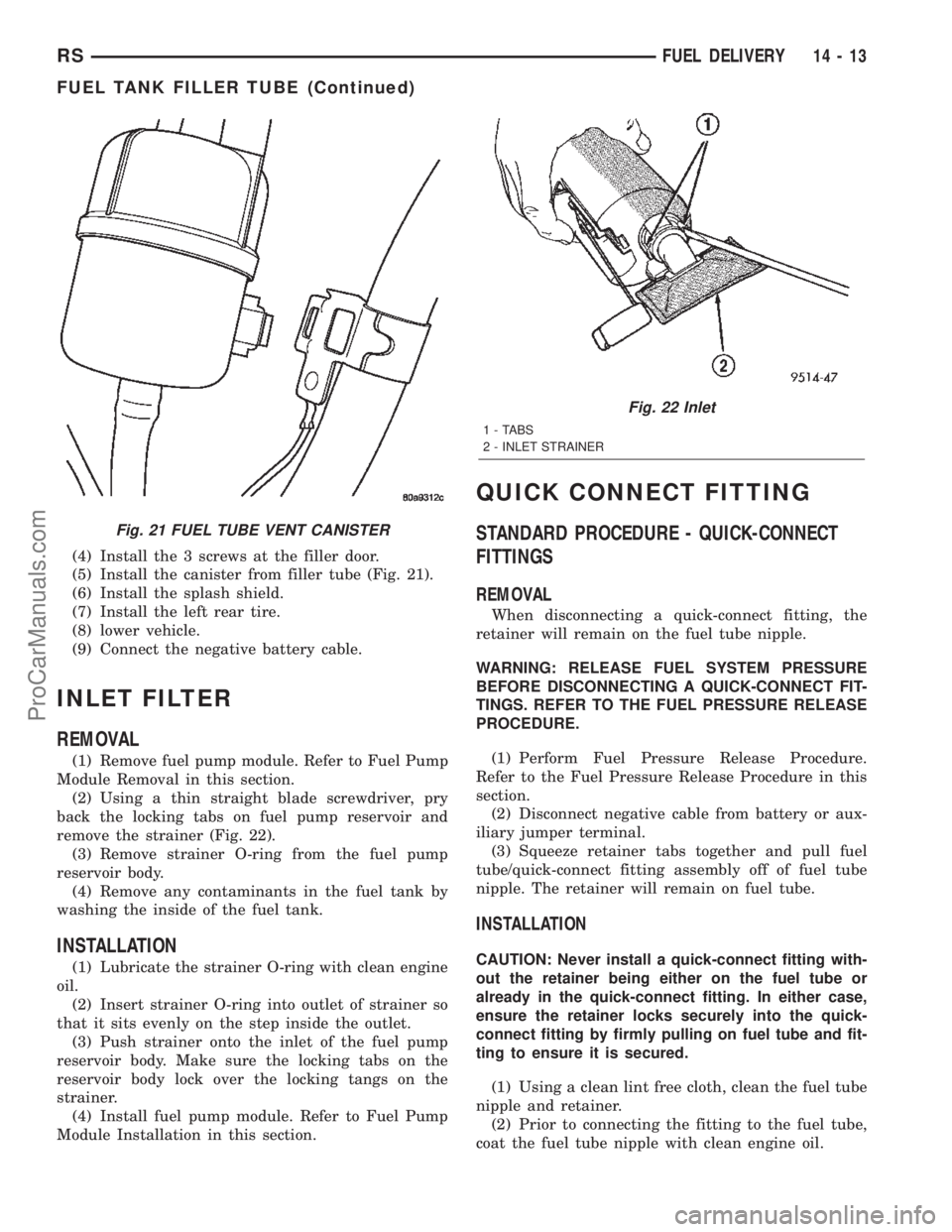
(2) Using a thin straight blade screwdriver, pry
back the locking tabs on fuel pump reservoir and
remove the strainer (Fig. 22).
(3) Remove strainer O-ring from the fuel pump
reservoir body.
(4) Remove any contaminants in the fuel tank by
washing the inside of the fuel tank.
INSTALLATION
(1) Lubricate the strainer O-ring with clean engine
oil.
(2) Insert strainer O-ring into outlet of strainer so
that it sits evenly on the step inside the outlet.
(3) Push strainer onto the inlet of the fuel pump
reservoir body. Make sure the locking tabs on the
reservoir body lock over the locking tangs on the
strainer.
(4) Install fuel pump module. Refer to Fuel Pump
Module Installation in this section.
QUICK CONNECT FITTING
STANDARD PROCEDURE - QUICK-CONNECT
FITTINGS
REMOVAL
When disconnecting a quick-connect fitting, the
retainer will remain on the fuel tube nipple.
WARNING: RELEASE FUEL SYSTEM PRESSURE
BEFORE DISCONNECTING A QUICK-CONNECT FIT-
TINGS. REFER TO THE FUEL PRESSURE RELEASE
PROCEDURE.
(1) Perform Fuel Pressure Release Procedure.
Refer to the Fuel Pressure Release Procedure in this
section.
(2) Disconnect negative cable from battery or aux-
iliary jumper terminal.
(3) Squeeze retainer tabs together and pull fuel
tube/quick-connect fitting assembly off of fuel tube
nipple. The retainer will remain on fuel tube.
INSTALLATION
CAUTION: Never install a quick-connect fitting with-
out the retainer being either on the fuel tube or
already in the quick-connect fitting. In either case,
ensure the retainer locks securely into the quick-
connect fitting by firmly pulling on fuel tube and fit-
ting to ensure it is secured.
(1) Using a clean lint free cloth, clean the fuel tube
nipple and retainer.
(2) Prior to connecting the fitting to the fuel tube,
coat the fuel tube nipple with clean engine oil.
Fig. 21 FUEL TUBE VENT CANISTER
Fig. 22 Inlet
1 - TABS
2 - INLET STRAINER
RSFUEL DELIVERY14-13
FUEL TANK FILLER TUBE (Continued)
ProCarManuals.com
Page 1465 of 2399
(3) Push the quick-connect fitting over the fuel
tube until theretainer seats and a click is heard.
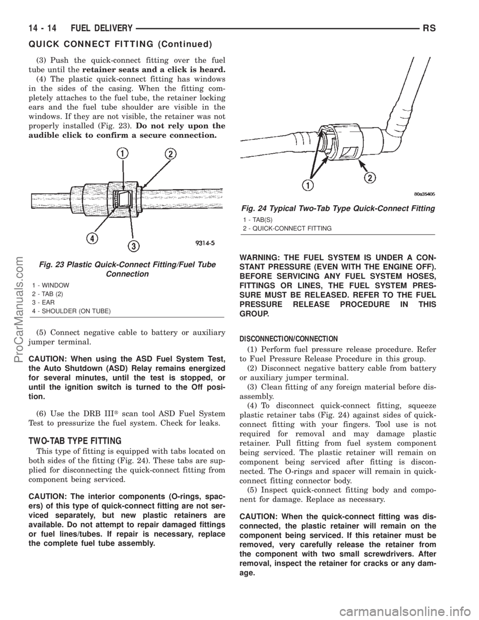
(4) The plastic quick-connect fitting has windows
in the sides of the casing. When the fitting com-
pletely attaches to the fuel tube, the retainer locking
ears and the fuel tube shoulder are visible in the
windows. If they are not visible, the retainer was not
properly installed (Fig. 23).Do not rely upon the
audible click to confirm a secure connection.
(5) Connect negative cable to battery or auxiliary
jumper terminal.
CAUTION: When using the ASD Fuel System Test,
the Auto Shutdown (ASD) Relay remains energized
for several minutes, until the test is stopped, or
until the ignition switch is turned to the Off posi-
tion.
(6) Use the DRB IIItscan tool ASD Fuel System
Test to pressurize the fuel system. Check for leaks.
TWO-TAB TYPE FITTING
This type of fitting is equipped with tabs located on
both sides of the fitting (Fig. 24). These tabs are sup-
plied for disconnecting the quick-connect fitting from
component being serviced.
CAUTION: The interior components (O-rings, spac-
ers) of this type of quick-connect fitting are not ser-
viced separately, but new plastic retainers are
available. Do not attempt to repair damaged fittings
or fuel lines/tubes. If repair is necessary, replace
the complete fuel tube assembly.WARNING: THE FUEL SYSTEM IS UNDER A CON-
STANT PRESSURE (EVEN WITH THE ENGINE OFF).
BEFORE SERVICING ANY FUEL SYSTEM HOSES,
FITTINGS OR LINES, THE FUEL SYSTEM PRES-
SURE MUST BE RELEASED. REFER TO THE FUEL
PRESSURE RELEASE PROCEDURE IN THIS
GROUP.
DISCONNECTION/CONNECTION
(1) Perform fuel pressure release procedure. Refer
to Fuel Pressure Release Procedure in this group.
(2) Disconnect negative battery cable from battery
or auxiliary jumper terminal.
(3) Clean fitting of any foreign material before dis-
assembly.
(4) To disconnect quick-connect fitting, squeeze
plastic retainer tabs (Fig. 24) against sides of quick-
connect fitting with your fingers. Tool use is not
required for removal and may damage plastic
retainer. Pull fitting from fuel system component
being serviced. The plastic retainer will remain on
component being serviced after fitting is discon-
nected. The O-rings and spacer will remain in quick-
connect fitting connector body.
(5) Inspect quick-connect fitting body and compo-
nent for damage. Replace as necessary.
CAUTION: When the quick-connect fitting was dis-
connected, the plastic retainer will remain on the
component being serviced. If this retainer must be
removed, very carefully release the retainer from
the component with two small screwdrivers. After
removal, inspect the retainer for cracks or any dam-
age.
Fig. 23 Plastic Quick-Connect Fitting/Fuel Tube
Connection
1 - WINDOW
2-TAB(2)
3 - EAR
4 - SHOULDER (ON TUBE)
Fig. 24 Typical Two-Tab Type Quick-Connect Fitting
1 - TAB(S)
2 - QUICK-CONNECT FITTING
14 - 14 FUEL DELIVERYRS
QUICK CONNECT FITTING (Continued)
ProCarManuals.com
Page 1466 of 2399
(6) Prior to connecting quick-connect fitting to
component being serviced, check condition of fitting
and component. Clean parts with a lint-free cloth.
Lubricate with clean engine oil.
(7) Insert quick-connect fitting to component being
serviced and into plastic retainer. When a connection
is made, a click will be heard.
(8) Verify a locked condition by firmly pulling on
fuel tube and fitting (15-30 lbs.).
(9) Connect negative cable to battery or auxiliary
jumper terminal.
(10) Use the DRB IIItscan tool ASD Fuel System
Test to pressurize the fuel system. Check for leaks.
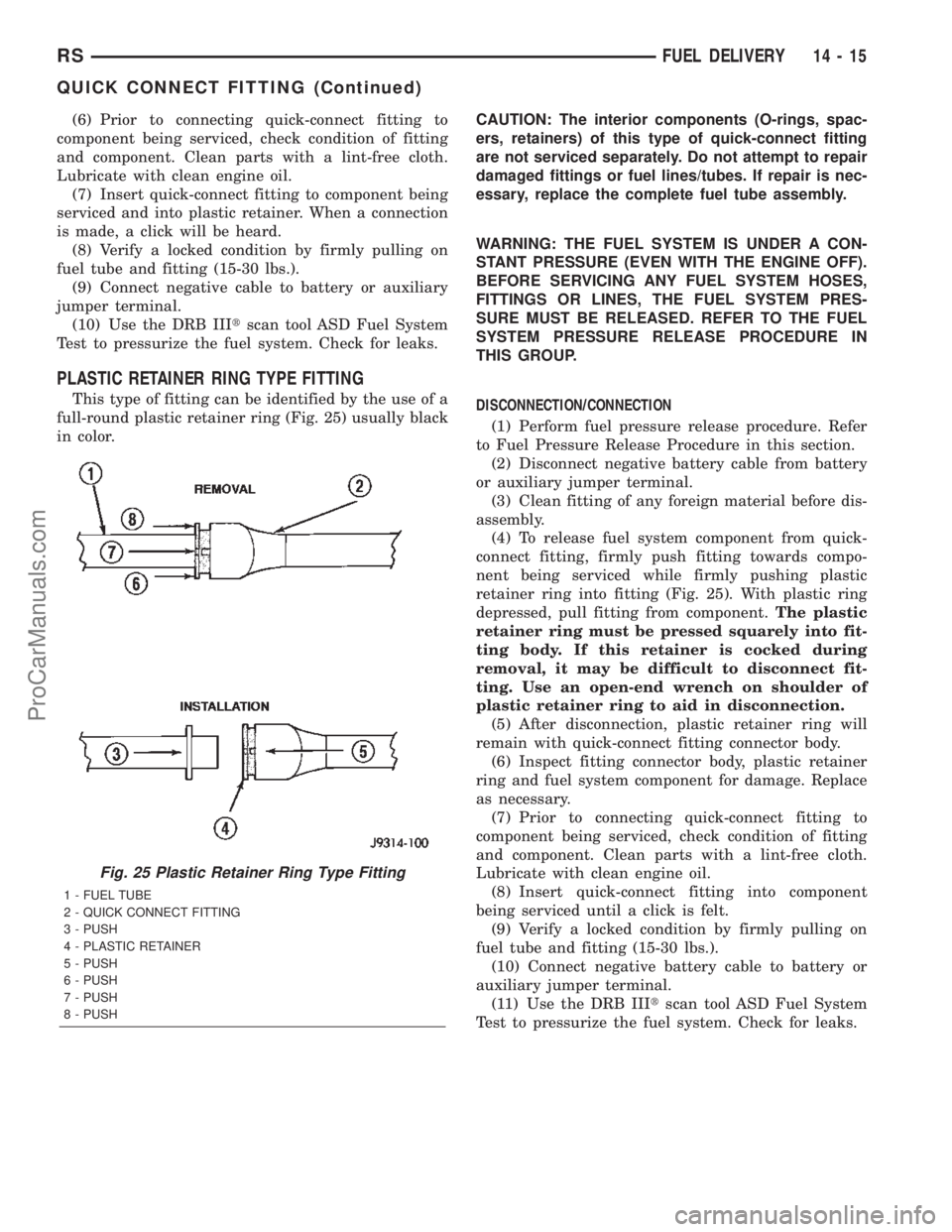
PLASTIC RETAINER RING TYPE FITTING
This type of fitting can be identified by the use of a
full-round plastic retainer ring (Fig. 25) usually black
in color.CAUTION: The interior components (O-rings, spac-
ers, retainers) of this type of quick-connect fitting
are not serviced separately. Do not attempt to repair
damaged fittings or fuel lines/tubes. If repair is nec-
essary, replace the complete fuel tube assembly.
WARNING: THE FUEL SYSTEM IS UNDER A CON-
STANT PRESSURE (EVEN WITH THE ENGINE OFF).
BEFORE SERVICING ANY FUEL SYSTEM HOSES,
FITTINGS OR LINES, THE FUEL SYSTEM PRES-
SURE MUST BE RELEASED. REFER TO THE FUEL
SYSTEM PRESSURE RELEASE PROCEDURE IN
THIS GROUP.
DISCONNECTION/CONNECTION
(1) Perform fuel pressure release procedure. Refer
to Fuel Pressure Release Procedure in this section.
(2) Disconnect negative battery cable from battery
or auxiliary jumper terminal.
(3) Clean fitting of any foreign material before dis-
assembly.
(4) To release fuel system component from quick-
connect fitting, firmly push fitting towards compo-
nent being serviced while firmly pushing plastic
retainer ring into fitting (Fig. 25). With plastic ring
depressed, pull fitting from component.The plastic
retainer ring must be pressed squarely into fit-
ting body. If this retainer is cocked during
removal, it may be difficult to disconnect fit-
ting. Use an open-end wrench on shoulder of
plastic retainer ring to aid in disconnection.
(5) After disconnection, plastic retainer ring will
remain with quick-connect fitting connector body.
(6) Inspect fitting connector body, plastic retainer
ring and fuel system component for damage. Replace
as necessary.
(7) Prior to connecting quick-connect fitting to
component being serviced, check condition of fitting
and component. Clean parts with a lint-free cloth.
Lubricate with clean engine oil.
(8) Insert quick-connect fitting into component
being serviced until a click is felt.
(9) Verify a locked condition by firmly pulling on
fuel tube and fitting (15-30 lbs.).
(10) Connect negative battery cable to battery or
auxiliary jumper terminal.
(11) Use the DRB IIItscan tool ASD Fuel System
Test to pressurize the fuel system. Check for leaks.
Fig. 25 Plastic Retainer Ring Type Fitting
1 - FUEL TUBE
2 - QUICK CONNECT FITTING
3 - PUSH
4 - PLASTIC RETAINER
5 - PUSH
6 - PUSH
7 - PUSH
8 - PUSH
RSFUEL DELIVERY14-15
QUICK CONNECT FITTING (Continued)
ProCarManuals.com