2002 CHRYSLER CARAVAN heating
[x] Cancel search: heatingPage 1368 of 2399
INSTALLATION
INSTALLATION - 2.5L TURBO DIESEL ENGINE
(1) Reassembly engine and transmission assembly
and install on engine cradle.
(2) Position engine and cradle assembly under
vehicle.
(3) Slowly lower the vehicle down over the engine
and cradle assembly.
(4) Install right engine mount bolts. Torque to
54N´m (40 ft. lbs.)
(5) Install left engine mount through bolt. Torque
to 75N´m (55 ft. lbs.)
(6) Raise vehicle and engine from engine cradle.
(7) Attach front engine mount bracket to lower
radiator support. Torque to 54N´m (40 ft. lbs.)
(8) Connect cabin heater coolant hose.
(9) Connect exhaust pipe to the turbocharger
downpipe flange. Torque to 28 N´m (250 in. lbs.)
(10) Connect reverse lamp electrical connector at
transmission.
(11) Connect both shifter cables (Refer to 21 -
TRANSMISSION/TRANSAXLE/MANUAL/GEAR
SHIFT CABLE - INSTALLATION).
(12) Connect the clutch slave cylinder quick dis-
connect connector (RHD only)(Refer to 6 - CLUTCH/
SLAVE CYLINDER - INSTALLATION).
(13) Install engine harness into bracket on trans-
mission.
(14) Lower vehicle.
(15) Connect fuel supply and return lines.
(16) Connect A/C lines to A/C compressor. Torque
to 23N´m (17 ft. lbs.)
(17) Route engine wiring harnes to proper location.
(18) Connect engine harness ground cables to
engine block
(19) Connect starter solenoid electrical connector
and battery feed wire to starter. Torque to 10N´m (90
in. lbs.)
(20) Connect A/C compressor, injection pump, glow
plugs, and coolant temperature sensor electrical con-
nectors.
(21) Connect generator electrical connector. Torque
to 9N´m (75 in. lbs.)
(22) Connect the fuel injector, fuel pressure sensor,
boost pressure/intake air temp sensor, cam sensor,
and egr solenoid electrical connectors (Fig. 8).
(23) Connect egr solenoid vacuum supply line to
brake boost vacuum supply line.(24) Connect brake booster vacuum supply line.
(25) Connect heater core return hose to coolant
pipe.
(26) Connect lower radiator hose to engine (Fig. 7).
(27) Install charger air cooler inlet hose (Fig. 6).
(28) Install charge air cooler outlet hose (Fig. 6).
(29) Connect upper radiator hose to engine (Fig.
7).
(30) Install battery shield.
(31) Install coolant reserve pressure container
(Refer to 7 - COOLING/ENGINE/COOLANT RECOV-
ERY PRESS CONTAINER - INSTALLATION).
(32) Install power steering reservoir and bracket
(Fig. 4).
(33) Raise vehicle
(34) Connect oil pressure sensor, oil temperature
sensor, engine speed sensor, and vehicle speed sensor
electrical connector (Fig. 9).
(35) Install suspension cradle in vehicle (Refer to
13 - FRAME & BUMPERS/FRAME/ENGINE CRA-
DLE CROSSMEMBER - INSTALLATION).
(36) Install both axle shaft assemblies (Refer to 3 -
DIFFERENTIAL & DRIVELINE/HALF SHAFT -
INSTALLATION).
(37) Connect the power steering supply, pressure,
and return lines to power steering pump (Fig. 4).
(38) Install the power steering line brackets on oil
pan (Fig. 4).
(39) Install lower splash shield and side panels.
(40) Install both front wheel and tire assemblies.
(41) Lower vehicle.
(42) Install air cleaner housing, MAF sensor, and
air intake tube assembly (Fig. 3).
(43) Refill transmission to proper level (Refer to 21
- TRANSMISSION/TRANSAXLE/MANUAL/FLUID -
STANDARD PROCEDURE).
(44) Refill engine coolant (Refer to 7 - COOLING/
ENGINE/COOLANT - STANDARD PROCEDURE).
(45) Recharge A/C system (Refer to 24 - HEATING
& AIR CONDITIONING/PLUMBING/REFRIGER-
ANT - STANDARD PROCEDURE) .
(46) Install engine cover (Refer to 9 - ENGINE -
INSTALLATION) (Fig. 2).
(47) Connect negative battery cable.
INSTALLATION - ENGINE COVER
(1) Install engine cover on engine.
(2) Install the engine cover mounting bolts (Fig.
10).
RGENGINE9a-7
ENGINE 2.5L TURBO DIESEL (Continued)
ProCarManuals.com
Page 1470 of 2399
The PCM compares the upstream and downstream
heated oxygen sensor inputs to measure catalytic con-
vertor efficiency. If the catalyst efficiency drops below
the minimum acceptable percentage, the PCM stores a
diagnostic trouble code in memory, after 2 trips.
During certain idle conditions, the PCM may enter
a variable idle speed strategy. During variable idle
speed strategy the PCM adjusts engine speed based
on the following inputs.
²A/C sense
²Battery voltage
²Battery temperature or Calculated Battery Tem-
perature
²Engine coolant temperature
²Engine run time
²Inlet/Intake air temperature
²Vehicle mileage
ACCELERATION MODE
This is a CLOSED LOOP mode. The PCM recog-
nizes an abrupt increase in Throttle Position sensor
output voltage or MAP sensor output voltage as a
demand for increased engine output and vehicle
acceleration. The PCM increases injector pulse width
in response to increased fuel demand.
²Wide Open Throttle-open loop
DECELERATION MODE
This is a CLOSED LOOP mode. During decelera-
tion the following inputs are received by the PCM:
²A/C sense
²Battery voltage
²Inlet/Intake air temperature
²Engine coolant temperature
²Crankshaft position (engine speed)
²Exhaust gas oxygen content (upstream heated
oxygen sensor)
²Knock sensor
²Manifold absolute pressure
²Throttle position sensor
²IAC motor (solenoid) control changes in response
to MAP sensor feedback
The PCM may receive a closed throttle input from
the Throttle Position Sensor (TPS) when it senses an
abrupt decrease in manifold pressure. This indicates a
hard deceleration (Open Loop). In response, the PCM
may momentarily turn off the injectors. This helps
improve fuel economy, emissions and engine braking.
WIDE-OPEN-THROTTLE MODE
This is an OPEN LOOP mode. During wide-open-
throttle operation, the following inputs are used by
the PCM:
²Inlet/Intake air temperature
²Engine coolant temperature
²Engine speed
²Knock sensor²Manifold absolute pressure
²Throttle position
When the PCM senses a wide-open-throttle condi-
tion through the Throttle Position Sensor (TPS) it de-
energizes the A/C compressor clutch relay. This
disables the air conditioning system and disables
EGR (if equipped).
The PCM adjusts injector pulse width to supply a
predetermined amount of additional fuel, based on
MAP and RPM.
IGNITION SWITCH OFF MODE
When the operator turns the ignition switch to the
OFF position, the following occurs:
²All outputs are turned off, unless 02 Heater
Monitor test is being run. Refer to the Emission sec-
tion for On-Board Diagnostics.
²No inputs are monitored except for the heated
oxygen sensors. The PCM monitors the heating ele-
ments in the oxygen sensors and then shuts down.
FUEL CORRECTION or ADAPTIVE MEMORIES
DESCRIPTION
In Open Loop, the PCM changes pulse width with-
out feedback from the O2 Sensors. Once the engine
warms up to approximately 30 to 35É F, the PCM
goes into closed loopShort Term Correctionand
utilizes feedback from the O2 Sensors. Closed loop
Long Term Adaptive Memoryis maintained above
170É to 190É F unless the PCM senses wide open
throttle. At that time the PCM returns to Open Loop
operation.
OPERATION
Short Term
The first fuel correction program that begins func-
tioning is the short term fuel correction. This system
corrects fuel delivery in direct proportion to the read-
ings from the Upstream O2 Sensor.
The PCM monitors the air/fuel ratio by using the
input voltage from the O2 Sensor. When the voltage
reaches its preset high or low limit, the PCM begins
to add or remove fuel until the sensor reaches its
switch point. The short term corrections then begin.
The PCM makes a series of quick changes in the
injector pulse-width until the O2 Sensor reaches its
opposite preset limit or switch point. The process
then repeats itself in the opposite direction.
Short term fuel correction will keep increasing or
decreasing injector pulse-width based upon the
upstream O2 Sensor input. The maximum range of
authority for short term memory is 25% (+/-) of base
pulse-width. Short term is violated and is lost when
ignition is turned OFF.
RSFUEL INJECTION14-19
FUEL INJECTION (Continued)
ProCarManuals.com
Page 1482 of 2399

The downstream heated oxygen sensor threads into
the outlet pipe at the rear of the catalytic convertor
(Fig. 22).
OPERATION
A single sensor ground is used for all O2 sensors (2
senors on 4 cyl. vehicles and 4 sensors on 6 cyl. vehi-
cles).
As vehicles accumulate mileage, the catalytic con-
vertor deteriorates. The deterioration results in a
less efficient catalyst. To monitor catalytic convertor
deterioration, the fuel injection system uses two
heated oxygen sensors. One sensor upstream of the
catalytic convertor, one downstream of the convertor.
The PCM compares the reading from the sensors to
calculate the catalytic convertor oxygen storage
capacity and converter efficiency. Also, the PCM uses
the upstream heated oxygen sensor input when
adjusting injector pulse width.
When the catalytic converter efficiency drops below
emission standards, the PCM stores a diagnostic
trouble code and illuminates the malfunction indica-
tor lamp (MIL).
The O2 sensors produce voltages from 0 to 1 volt,
depending upon the oxygen content of the exhaust
gas. When a large amount of oxygen is present
(caused by a lean air/fuel mixture, can be caused by
misfire and exhaust leaks), the sensors produces a
low voltage. When there is a lesser amount of oxygen
present (caused by a rich air/fuel mixture, can be
caused by internal engine problems) it produces a
higher voltage. By monitoring the oxygen content
and converting it to electrical voltage, the sensors act
as a rich-lean switch.The oxygen sensors are equipped with a heating
element that keeps the sensors at proper operating
temperature during all operating modes. Maintaining
correct sensor temperature at all times allows the
system to enter into closed loop operation sooner.
Also, it allows the system to remain in closed loop
operation during periods of extended idle.
In Closed Loop operation the PCM monitors the O2
sensors input (along with other inputs) and adjusts
the injector pulse width accordingly. During Open
Loop operation the PCM ignores the O2 sensor input.
The PCM adjusts injector pulse width based on pre-
programmed (fixed) values and inputs from other
sensors.
The Automatic Shutdown (ASD) relay supplies bat-
tery voltage to both the upstream and downstream
heated oxygen sensors. The oxygen sensors are
equipped with a heating element. The heating ele-
ments reduce the time required for the sensors to
reach operating temperature. The PCM uses pulse
width modulation to control the ground side of the
heater to regulate the temperature on 4 cyl.
upstream O2 heater only. All other 4 cyl. and 6 cyl.
O2 heaters do not use pulse width modulation.
UPSTREAM OXYGEN SENSOR
The input from the upstream heated oxygen sensor
tells the PCM the oxygen content of the exhaust gas.
Based on this input, the PCM fine tunes the air-fuel
ratio by adjusting injector pulse width.
The sensor input switches from 0 to 1 volt, depend-
ing upon the oxygen content of the exhaust gas in
the exhaust manifold. When a large amount of oxy-
gen is present (caused by a lean air-fuel mixture), the
sensor produces voltage as low as 0.1 volt. When
there is a lesser amount of oxygen present (rich air-
fuel mixture) the sensor produces a voltage as high
as 1.0 volt. By monitoring the oxygen content and
converting it to electrical voltage, the sensor acts as
a rich-lean switch.
The heating element in the sensor provides heat to
the sensor ceramic element. Heating the sensor
allows the system to enter into closed loop operation
sooner. Also, it allows the system to remain in closed
loop operation during periods of extended idle.
In Closed Loop, the PCM adjusts injector pulse
width based on the upstream heated oxygen sensor
input along with other inputs. In Open Loop, the
PCM adjusts injector pulse width based on prepro-
grammed (fixed) values and inputs from other sen-
sors.
DOWNSTREAM OXYGEN SENSOR
The downstream heated oxygen sensor input is
used to detect catalytic convertor deterioration. As
the convertor deteriorates, the input from the down-
Fig. 22 O2 SENSOR DOWNSTREAM 1/2 - 2.4/3.3/
3.8L
RSFUEL INJECTION14-31
O2 SENSOR (Continued)
ProCarManuals.com
Page 1553 of 2399
INSTALLATION
INSTALLATION - 2.4L ENGINE
(1) Remove any used O-rings from ends of power
steering hose.
(2) Using a lint free towel, wipe clean hose ends,
power steering pump fitting and steering gear port.
(3) Install new O-ring on power steering gear end
of return hose. Lubricate O-ring using clean power
steering fluid.
CAUTION: Use care not to bend tube ends of the
power steering hoses when installing. Leaks and
restrictions may occur.
CAUTION: If a new return hose is being installed
and it does not have an insulating heat sleeve
installed, the heat shield from the original hose
must be transferred before hose installation.
(4) Route hose along rear of cradle crossmember
and start gear end of hose into gear port. Do not
tighten hose tube nut at this time.
(5) Attach hose to suspension cradle crossmember
using two routing clamps and bolts (Fig. 19). Tighten
clamp bolts to 23 N´m (200 in. lbs.) torque.
(6) Tighten return hose tube nut at power steering
gear port to 31 N´m (275 in. lbs.) torque.
(7) Install the power steering fluid cooler on the
cradle crossmember reinforcement (Fig. 23). Install
the mounting bolts and tighten to 11 N´m (100 in.
lbs.).
CAUTION: Power steering fluid hoses must remain
away from the exhaust system and must not come
in contact with any unfriendly surfaces on the vehi-
cle.
(8) Route pump end of hose over cradle crossmem-
ber toward pump avoiding tight bends or kinking.
(9) Install return hose onto power steering pump
return fitting and secure with hose clamp (Fig. 19).
Tighten the screw-type clamp to a torque of 2 N´m
(18 in. lbs.).
CAUTION: To prevent overheating of power steering
fluid return hose, protective heat shield sleeve must
cover entire rubber hose.
(10) Slide insulating heat shield up over the clamp
on the return hose and tie-strap it in place.
(11) Install front emissions vapor canister. (Refer
to 25 - EMISSIONS CONTROL/EVAPORATIVE
EMISSIONS/VAPOR CANISTER - INSTALLATION)
(12) Lower vehicle.(13) Fill and bleed the power steering system
using the Power Steering Pump Initial Operation
Procedure. (Refer to 19 - STEERING/PUMP - STAN-
DARD PROCEDURE)
(14) Inspect system for leaks.
INSTALLATION - 3.3L/3.8L ENGINE
(1) Remove any used O-rings from ends of power
steering hose.
(2) Using a lint free towel, wipe clean hose ends
and power steering gear hose port.
(3) Install a new O-ring on gear port end of power
steering fluid hose. Lubricate O-ring using clean
power steering fluid.
CAUTION: Use care not to bend tube ends of the
power steering hoses when installing. Leaks and
restrictions may occur.
CAUTION: Power steering fluid hoses must remain
away from the exhaust system and must not come
in contact with any unfriendly surfaces on the vehi-
cle.
(4) Route hose (with cooler attached) up toward
reservoir avoiding tight bends or kinking.
(5) Start steering gear end of hose into gear port.
Do not tighten hose tube nut at this time.
(6) Attach return hose tubes to suspension cradle
crossmember using routing clamp and bolt (Fig. 20).
Tighten clamp bolt to 23 N´m (200 in. lbs.) torque.
(7) Install the power steering fluid cooler on the
cradle crossmember reinforcement (Fig. 23). Install
the mounting bolts and tighten to 11 N´m (100 in.
lbs.). When installing mounting bolts, include pres-
sure hose routing clamp.
(8) Tighten hose tube nut at power steering gear
port to 31 N´m (275 in. lbs.) torque.
(9) Install front emissions vapor canister. (Refer to
25 - EMISSIONS CONTROL/EVAPORATIVE EMIS-
SIONS/VAPOR CANISTER - INSTALLATION)
(10) Lower vehicle.
(11) Install return hose tube into retainer on ABS
bracket (Fig. 20). Close the bracket.
(12) Install return hose onto reservoir (Fig. 21).
Slide the hose clamp into position on fluid reservoir
and attach it.Be sure hose clamp in installed
past bead on fluid reservoir fitting.
(13) Fill and bleed power steering system using
the Power Steering Pump Initial Operation Proce-
dure. (Refer to 19 - STEERING/PUMP - STANDARD
PROCEDURE)
(14) Inspect system for leaks.
19 - 50 PUMPRS
HOSE - POWER STEERING RETURN (Continued)
ProCarManuals.com
Page 1807 of 2399
(6) Adjust transmission fluid level shown on the
indicator according to the chart.
(7) Check transmission for leaks.
Low fluid level can cause a variety of conditions
because it allows the pump to take in air along with
the fluid. As in any hydraulic system, air bubbles
make the fluid spongy, therefore, pressures will be
low and build up slowly.
Improper filling can also raise the fluid level too
high. When the transaxle has too much fluid, the
gears churn up foam and cause the same conditions
which occur with a low fluid level.
In either case, air bubbles can cause overheating
and/or fluid oxidation, and varnishing. This can
interfere with normal valve, clutch, and accumulator
operation. Foaming can also result in fluid escaping
from the transaxle vent where it may be mistaken
for a leak.
FLUID CONDITION
Along with fluid level, it is important to check the
condition of the fluid. When the fluid smells burned,
and is contaminated with metal or friction material
particles, a complete transaxle recondition is proba-
bly required. Be sure to examine the fluid on the dip-
stick closely. If there is any doubt about its condition,
drain out a sample for a double check.
MopartATF+4 (Automatic Transmission Fluid-
Type 9602) when new is red in color. The ATF is dyed
red so it can be identified from other fluids used in
the vehicle such as engine oil or antifreeze. The red
color is not permanent and is not an indicator of fluid
condition. As the vehicle is driven, the ATF will begin
to look darker in color and may eventually become
brown.This is normal.ATF+4 also has a unique
odor that may change with age. Consequently,odor
and color cannot be used to indicate the fluid
condition or the need for a fluid change.
After the fluid has been checked, seat the dipstick
fully to seal out water and dirt.
STANDARD PROCEDURE - FLUID AND FILTER
SERVICE
NOTE: Refer to the maintenance schedules in
LUBRICATION and MAINTENANCE, or the vehicle
owner's manual, for the recommended maintenance
(fluid/filter change) intervals for this transaxle.
NOTE: Only fluids of the type labeled MoparTATF+4
(Automatic Transmission Fluid) Type 9602 should
be used. A filter change should be made at the time
of the transmission oil change. The magnet (on the
inside of the oil pan) should also be cleaned with a
clean, dry cloth.NOTE: If the transaxle is disassembled for any rea-
son, the fluid and filter should be changed.
FLUID/FILTER SERVICE (RECOMMENDED)
(1) Raise vehicle on a hoist. Refer to LUBRICA-
TION and MAINTENANCE for proper procedures.
Place a drain container with a large opening, under
transaxle oil pan.
(2) Loosen pan bolts and tap the pan at one corner
to break it loose allowing fluid to drain, then remove
the oil pan.
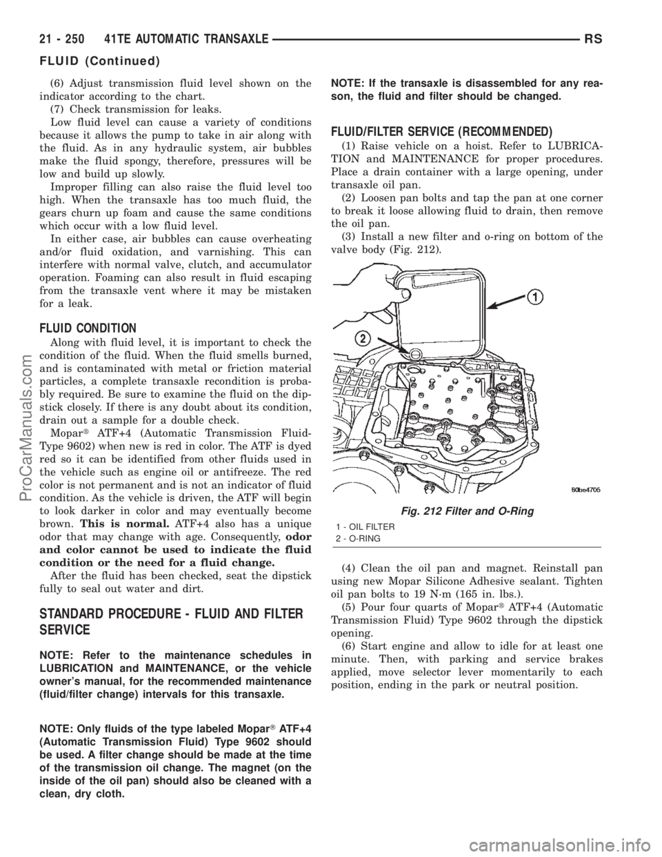
(3) Install a new filter and o-ring on bottom of the
valve body (Fig. 212).
(4) Clean the oil pan and magnet. Reinstall pan
using new Mopar Silicone Adhesive sealant. Tighten
oil pan bolts to 19 N´m (165 in. lbs.).
(5) Pour four quarts of MopartATF+4 (Automatic
Transmission Fluid) Type 9602 through the dipstick
opening.
(6) Start engine and allow to idle for at least one
minute. Then, with parking and service brakes
applied, move selector lever momentarily to each
position, ending in the park or neutral position.
Fig. 212 Filter and O-Ring
1 - OIL FILTER
2 - O-RING
21 - 250 41TE AUTOMATIC TRANSAXLERS
FLUID (Continued)
ProCarManuals.com
Page 1979 of 2399
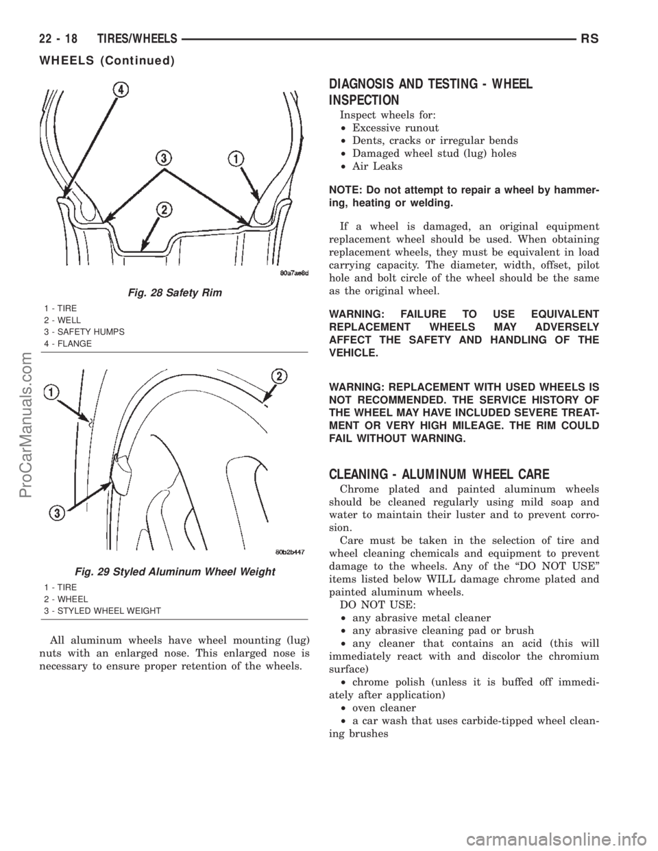
All aluminum wheels have wheel mounting (lug)
nuts with an enlarged nose. This enlarged nose is
necessary to ensure proper retention of the wheels.
DIAGNOSIS AND TESTING - WHEEL
INSPECTION
Inspect wheels for:
²Excessive runout
²Dents, cracks or irregular bends
²Damaged wheel stud (lug) holes
²Air Leaks
NOTE: Do not attempt to repair a wheel by hammer-
ing, heating or welding.
If a wheel is damaged, an original equipment
replacement wheel should be used. When obtaining
replacement wheels, they must be equivalent in load
carrying capacity. The diameter, width, offset, pilot
hole and bolt circle of the wheel should be the same
as the original wheel.
WARNING: FAILURE TO USE EQUIVALENT
REPLACEMENT WHEELS MAY ADVERSELY
AFFECT THE SAFETY AND HANDLING OF THE
VEHICLE.
WARNING: REPLACEMENT WITH USED WHEELS IS
NOT RECOMMENDED. THE SERVICE HISTORY OF
THE WHEEL MAY HAVE INCLUDED SEVERE TREAT-
MENT OR VERY HIGH MILEAGE. THE RIM COULD
FAIL WITHOUT WARNING.
CLEANING - ALUMINUM WHEEL CARE
Chrome plated and painted aluminum wheels
should be cleaned regularly using mild soap and
water to maintain their luster and to prevent corro-
sion.
Care must be taken in the selection of tire and
wheel cleaning chemicals and equipment to prevent
damage to the wheels. Any of the ªDO NOT USEº
items listed below WILL damage chrome plated and
painted aluminum wheels.
DO NOT USE:
²any abrasive metal cleaner
²any abrasive cleaning pad or brush
²any cleaner that contains an acid (this will
immediately react with and discolor the chromium
surface)
²chrome polish (unless it is buffed off immedi-
ately after application)
²oven cleaner
²a car wash that uses carbide-tipped wheel clean-
ing brushes
Fig. 28 Safety Rim
1 - TIRE
2 - WELL
3 - SAFETY HUMPS
4 - FLANGE
Fig. 29 Styled Aluminum Wheel Weight
1 - TIRE
2 - WHEEL
3 - STYLED WHEEL WEIGHT
22 - 18 TIRES/WHEELSRS
WHEELS (Continued)
ProCarManuals.com
Page 1989 of 2399
PANEL SECTIONING
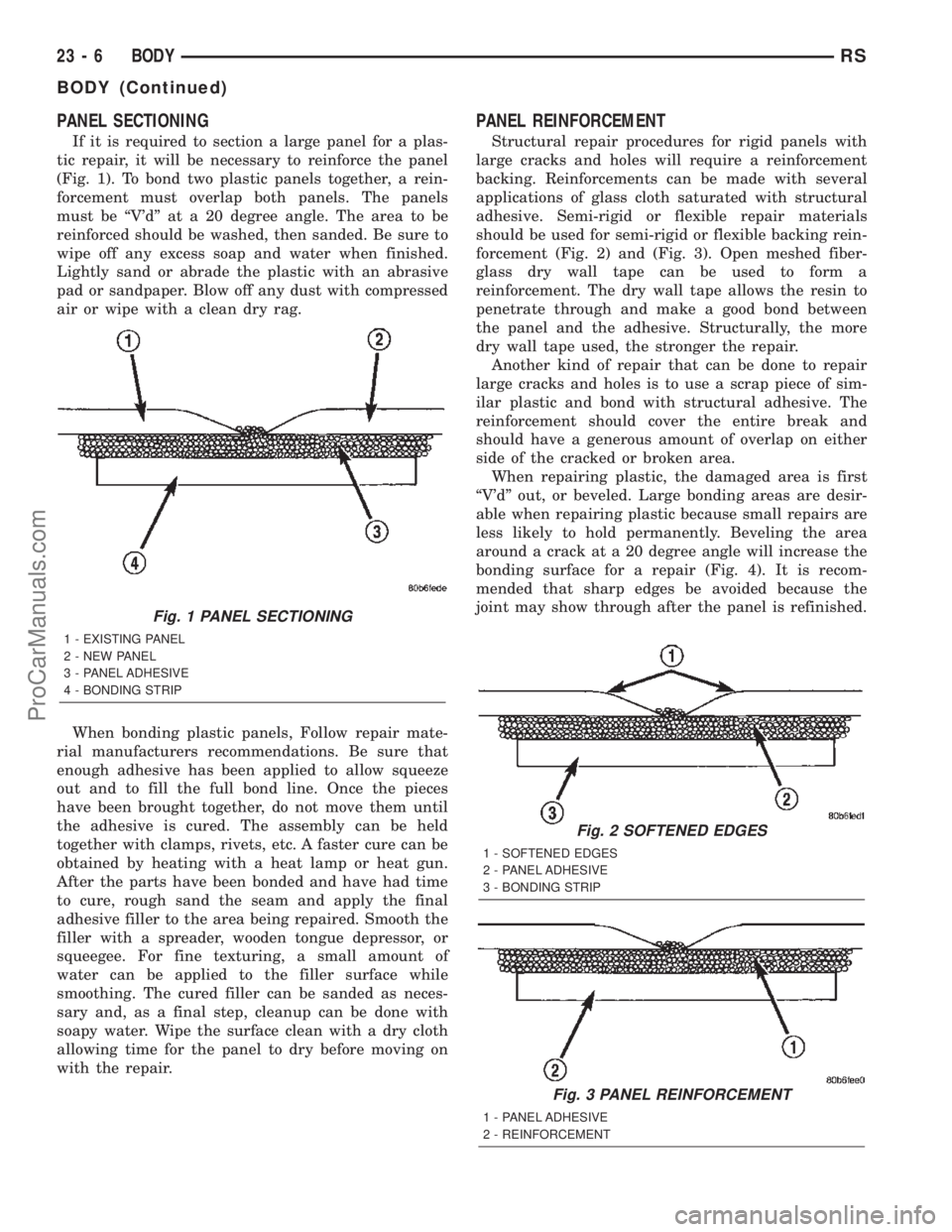
If it is required to section a large panel for a plas-
tic repair, it will be necessary to reinforce the panel
(Fig. 1). To bond two plastic panels together, a rein-
forcement must overlap both panels. The panels
must be ªV'dº at a 20 degree angle. The area to be
reinforced should be washed, then sanded. Be sure to
wipe off any excess soap and water when finished.
Lightly sand or abrade the plastic with an abrasive
pad or sandpaper. Blow off any dust with compressed
air or wipe with a clean dry rag.
When bonding plastic panels, Follow repair mate-
rial manufacturers recommendations. Be sure that
enough adhesive has been applied to allow squeeze
out and to fill the full bond line. Once the pieces
have been brought together, do not move them until
the adhesive is cured. The assembly can be held
together with clamps, rivets, etc. A faster cure can be
obtained by heating with a heat lamp or heat gun.
After the parts have been bonded and have had time
to cure, rough sand the seam and apply the final
adhesive filler to the area being repaired. Smooth the
filler with a spreader, wooden tongue depressor, or
squeegee. For fine texturing, a small amount of
water can be applied to the filler surface while
smoothing. The cured filler can be sanded as neces-
sary and, as a final step, cleanup can be done with
soapy water. Wipe the surface clean with a dry cloth
allowing time for the panel to dry before moving on
with the repair.
PANEL REINFORCEMENT
Structural repair procedures for rigid panels with
large cracks and holes will require a reinforcement
backing. Reinforcements can be made with several
applications of glass cloth saturated with structural
adhesive. Semi-rigid or flexible repair materials
should be used for semi-rigid or flexible backing rein-
forcement (Fig. 2) and (Fig. 3). Open meshed fiber-
glass dry wall tape can be used to form a
reinforcement. The dry wall tape allows the resin to
penetrate through and make a good bond between
the panel and the adhesive. Structurally, the more
dry wall tape used, the stronger the repair.
Another kind of repair that can be done to repair
large cracks and holes is to use a scrap piece of sim-
ilar plastic and bond with structural adhesive. The
reinforcement should cover the entire break and
should have a generous amount of overlap on either
side of the cracked or broken area.
When repairing plastic, the damaged area is first
ªV'dº out, or beveled. Large bonding areas are desir-
able when repairing plastic because small repairs are
less likely to hold permanently. Beveling the area
around a crack at a 20 degree angle will increase the
bonding surface for a repair (Fig. 4). It is recom-
mended that sharp edges be avoided because the
joint may show through after the panel is refinished.
Fig. 1 PANEL SECTIONING
1 - EXISTING PANEL
2 - NEW PANEL
3 - PANEL ADHESIVE
4 - BONDING STRIP
Fig. 2 SOFTENED EDGES
1 - SOFTENED EDGES
2 - PANEL ADHESIVE
3 - BONDING STRIP
Fig. 3 PANEL REINFORCEMENT
1 - PANEL ADHESIVE
2 - REINFORCEMENT
23 - 6 BODYRS
BODY (Continued)
ProCarManuals.com
Page 2244 of 2399
HEATING & AIR CONDITIONING
TABLE OF CONTENTS
page page
HEATING & AIR CONDITIONING
DESCRIPTION
DESCRIPTION - SINGLE ZONE...........1
DESCRIPTION - DUAL ZONE.............1
DESCRIPTION - MANUAL THREE ZONE.....1
DESCRIPTION - THREE ZONE AUTOMATIC
TEMPERATURE CONTROL...............2
OPERATION
OPERATION - DUAL ZONE...............3
OPERATION - MANUAL THREE ZONE......3
OPERATION - THREE ZONE ATC..........4
DIAGNOSIS AND TESTING
DIAGNOSIS AND TESTING - A/C COOL
DOWN TEST..........................5DIAGNOSIS AND TESTING - A/C
PERFORMANCE TEST..................5
DIAGNOSIS AND TESTING - HEATER
PERFORMANCE TEST..................6
SPECIFICATIONS - HEATER-A/C SYSTEM.....7
CONTROLS - FRONT......................8
CONTROLS - REAR......................29
DISTRIBUTION - FRONT...................39
DISTRIBUTION - REAR....................51
PLUMBING - FRONT.....................59
PLUMBING - REAR......................97
DIESEL SUPPLEMENTAL HEATER - DCHA -
BUX.................................109
HEATING & AIR
CONDITIONING
DESCRIPTION
DESCRIPTION - SINGLE ZONE
A single zone heating and air conditioning system
allows one temperature setting for the entire vehicle.
The full range of temperatures that the system can
produce are available by rotating the temperature
control located in control panel.
The control panel and integral computer is
mounted in the instrument panel.
DESCRIPTION - DUAL ZONE
A manual Dual Zone Heating and Air Conditioning
system allows completely independent side-to-side
tempeture control of the discharge air.
The Dual Zone Heating and Air Conditioning sys-
tem includes a dust and odor air filter. The filter ele-
ment is the same size as the air conditioning
evaporator to ensure ample capacity. A door at the
base of the heating and air conditioning housing
below the glove box provides easy access to the filter
element.
The control panel and integral computer is located
in the instrument panel.
The instrument panel mounted control and inte-
gral computer contains:
²a power button which allows the system to be
completely turned off. Contains an LED that illumi-
nates to show when the function is operational.²rear window defogger on/off switch. Contains an
LED that illuminates to show when the function is
operational.
²slide controls for completely independent side-to-
side temperature control of the discharged air. The
full range of temperature that the system can pro-
duce in any mode is available on either side of the
vehicle by independently positioning the slide con-
trols on the instrument panel.
²air recirculation on/off switch. The Recirculate
button contains an LED that illuminates to show
when the function is in operation.
²air conditioning on/off switch. The Snowflake
button contains an LED that illuminates to shown
when the function is in operation.
²rotary knob for fan speed selection.
²a rotary knob for mode control.
DESCRIPTION - MANUAL THREE ZONE
The fully adjustable Three-Zone front and rear
heating and air conditioning system allows interme-
diate seat passengers the ability to regulate air tem-
perature as well as fan speed. All controls are
identified by ISO graphic symbols.
The Three Zone Heating and Air Conditioning sys-
tem includes a dust and odor air filter. The filter ele-
ment is the same size as the air conditioning
evaporator to ensure ample capacity. A door at the
base of the heating and air conditioning housing
below the glove box provides easy access to the filter
element.
RSHEATING & AIR CONDITIONING24-1
ProCarManuals.com